1987 SUZUKI GRAND VITARA check engine light
[x] Cancel search: check engine lightPage 26 of 962
8. PCV VALVE REPLACEMENT
1) Disconnect crankcase ventilation hose from
PCV valve.
2) Remove PCV valve from intake manifold.
3) Wind sealing tape on thread of the new valve
and install it securely.
Tightenlng torque
for PCV valve
15-25 N.m
1.5-2.5 kg-m,
11 .O-18.0 lb-ft
4) Install hose and clamp it securely.
9. OXYGEN SENSOR REPLACEMENT
[Canadian specification vehicle]
When the odometer indicates 50,000 and 100,000
miles, replace oxygen sensor as follows.
CAUTION:
To avoid the danger of being burned, do
not touch the exhaust system when the
system is hot. This work should be perform-
ed when the system is cool.
1) Disconnect battery negative cable from
battery and disconnect oxygen sensor wire at
the coupler.
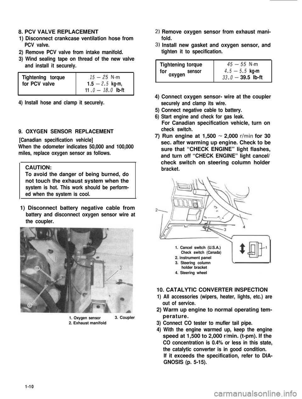
1. Oxygen sensor
2. Exhaust manifold
3. Coupler
2) Remove oxygen sensor from exhaust mani-
fold.
3) Install new gasket and oxygen sensor, and
tighten it to specification.
-Tightening45torque55 N-m
4.5-foroxygensensor5.5 kg-m
33.0-39.5 lb-ft
4) Connect oxygen sensor- wire at the coupler
securely and clamp its wire.
5) Connect negative cable to battery.
6) Start engine and check for gas leak.
For Canadian specification vehicle, turn on
check switch.
7) Run engine at 1,500 - 2,000 r/min for 30
sec. after warming up engine. Check to be
sure that “CHECK ENGINE” light flashes,
and turn off “CHECK ENGINE” light cancel/
check switch on steering column holder
bracket.
1. Cancel switch (U.S.A.)Check switch (Canada)
2. instrument panel
3. Steering columnholder bracket
4. Steering wheel
10. CATALYTIC CONVERTER INSPECTION
1) All accessories (wipers, heater, lights, etc.) are
out of service.
2) Warm up engine to normal operating tem-
perature.
3) Connect CO tester to mufler tail pipe.
4) With the engine warmed up, keep the engine
speed at 1,500 to 2,000 r/min. (t-pm). If the
CO concentration is 0.4% or less in this state,
the catalytic converter is in good condition.
If it exceeds the specification, refer to DIA-
GNOSIS (p. 5-15).
1-10
Page 28 of 962
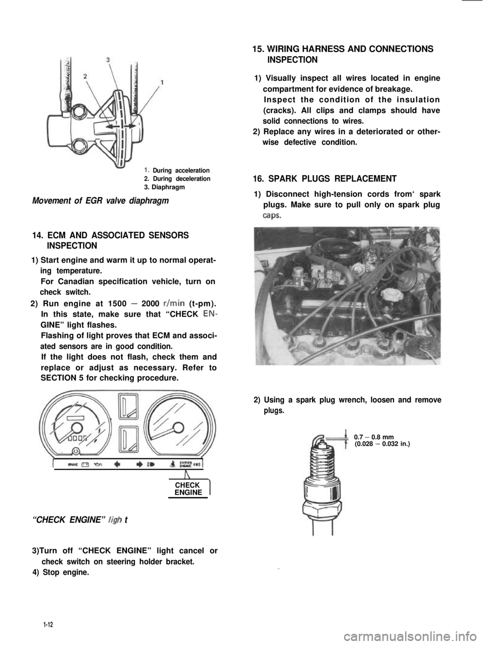
1. During acceleration
2. During deceleration
3. Diaphragm
Movement of EGR valve diaphragm
14. ECM AND ASSOCIATED SENSORS
INSPECTION
1) Start engine and warm it up to normal operat-
ing temperature.
For Canadian specification vehicle, turn on
check switch.
2) Run engine at 1500 - 2000 r/min (t-pm).
In this state, make sure that “CHECK EON-
GINE” light flashes.
Flashing of light proves that ECM and associ-
ated sensors are in good condition.
If the light does not flash, check them and
replace or adjust as necessary. Refer to
SECTION 5 for checking procedure.
A
CHECKENGINE
“CHECK ENGINE” ligh t
3)Turn off “CHECK ENGINE” light cancel or
check switch on steering holder bracket.
4) Stop engine.
15. WIRING HARNESS AND CONNECTIONS
INSPECTION
1) Visually inspect all wires located in engine
compartment for evidence of breakage.
Inspect the condition of the insulation
(cracks). All clips and clamps should have
solid connections to wires.
2) Replace any wires in a deteriorated or other-
wise defective condition.
16. SPARK PLUGS REPLACEMENT
1) Disconnect high-tension cords from‘ spark
plugs. Make sure to pull only on spark plug
caps.
2) Using a spark plug wrench, loosen and remove
plugs.
0.7 - 0.8 mm(0.028 - 0.032 in.)
1-12
Page 32 of 962
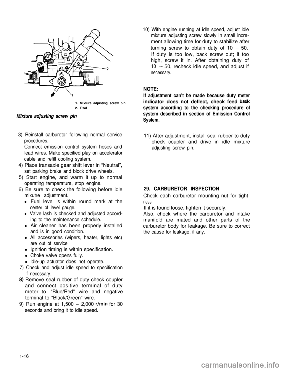
1. Mixture adjusting screw pin
2. Rod
Mixture adjusting screw pin
10) With engine running at idle speed, adjust idle
mixture adjusting screw slowly in small incre-
ment allowing time for duty to stabilize after
turning screw to obtain duty of 10 - 50.
If duty is too low, back screw out; if too
high, screw it in. After obtaining duty of
10- 50, recheck idle speed, and adjust if
necessary.
NOTE:
If adjustment can’t be made because duty meter
indicator does not deflect, check feed baCk
system according to the checking procedure of
system described in section of Emission Control
System.
3) Reinstall carburetor following normal service
procedures.
Connect emission control system hoses and
lead wires. Make specified play on accelerator
cable and refill cooling system.
11) After adjustment, install seal rubber to duty
check coupler and drive in idle mixture
adjusting screw pin.
4) Place transaxle gear shift lever in “Neutral”,
set parking brake and block drive wheels.
5) Start engine, and warm it up to normal
operating temperature, stop engine.
6) Be sure to check the following before idle
mixutre adjustment.
l Fuel level is within round mark at the
center of level gauge.
l Valve lash is checked and adjusted accord-
ing to the maintenance schedule.
l Air cleaner has been properly installed
and is in good condition.
l All accessories (wipers, heater, lights etc)
are out of service.
29. CARBURETOR INSPECTION
Check each carburetor mounting nut for tight-
ness.
If it is found loose, tighten it securely.
Also, check where the carburetor and intake
manifold are mated and other parts of the
carburetor body for leakage. Be sure to correct
the cause for leakage, if any.
l Ignition timing is within specification.
l Choke valve opens fully.
l Idle-up actuator does not operate.
7) Check and adjust idle speed to specification
if necessary.
8) Remove seal rubber of duty check coupler
and connect positive terminal of duty
meter to“Blue/Red” wire and negative
terminal to “Black/Green” wire.
9) Run engine at 1,500 - 2,000 r/min for 30
seconds and bring it to idle speed.
1-16
Page 55 of 962

Condition
Starter will not run
at all, or runs but
runs too slow to
crank with full
force
Starter does not
stop running.
2-11. ALTERNATOR
Condition
Battery quickly
becomes over-
discharged.
Charge light does not
light with ignition ON
and engine off
Alternator noise
Possible cause
Magnet switch trouble
1. Lead wire socket loose in place
2. Burnt contact plate, or poor contacting
action
3. Open-circuit in pull-in coil
4. Open-circuit in holding coil
Starter proper trouble
1. Brushes seating poorly or worn down
2. Burnt commutator
3. Open-circuit in armature winding
4. Worn-down starter.
1. Fused contact points of magnet-switch
contact plate
2. Short-circuit between turns of magnet-
switch coil (layer short-circuit)
3. Failure of returning action in ignition
switch
Possible cause
1. Loose or broken “V” belt
2. Battery cables loose, corroded or worn
3. Low level of battery electrolyte
4. Defective battery cell plates
5. Insufficient contact in battery terminal
connection.
6. Excessive electrical load
7. IC regulator or alternator faulty
8. Defective idle up system
1. Fuse blown
2. Light burned out
3. Loose wiring connection
4. IC regulator faulty
1. Worn, loose or otherwise defective bearings
Correction
Retighten
Replace, or repair
Replace
Replace
Repair or replace
Repair or replace
Replace
Replace
Repair or replace
Replace
Replace
Correction
Adjust or replace
Repair or replcae
Replace
Replace the battery
Clean and retighten
Check charging system
Replace
Repair or replace
Check fuse
Replace light
Tighten loose connection!
Replace
i
Replace
2-17
Page 112 of 962
Engine Coolant
This subject is covered in SECTION 6 ENGINE
COOLING SYSTEM.
Exhaust Line and Muffler
Inspect each exhaust line connection for tight-
ness, and examine muffler and other parts for
evidence of breakage and leakage of gases.
Repair or replace defective parts, if any.
Compression Pressure Measurement
Check compression pressure on all four cylinders
as follows:
1) Warm up engine.
2) Stop engine after warming up.
3) Remove all spark plugs and disconnect
high tension cord from ignition coil.
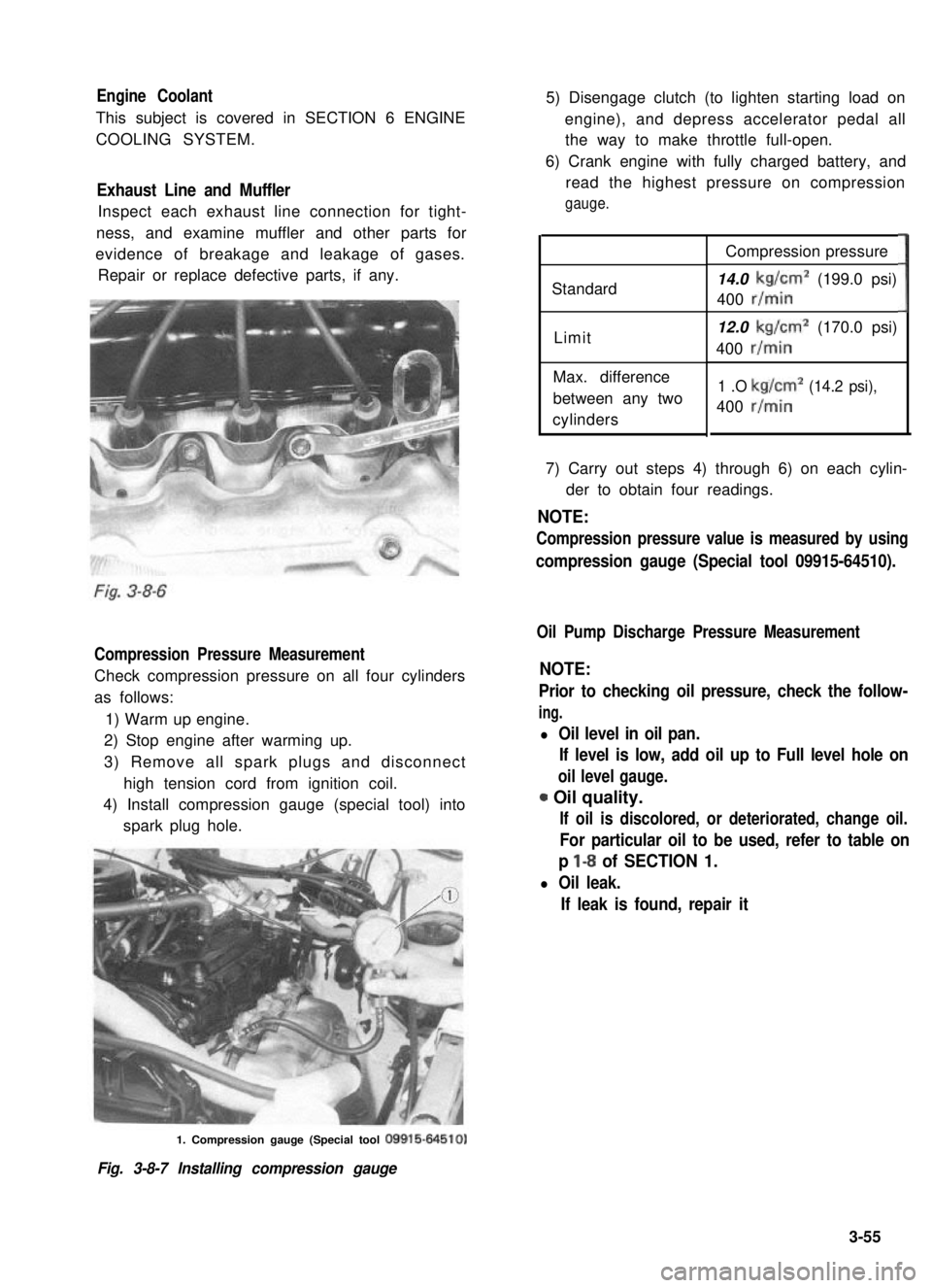
4) Install compression gauge (special tool) into
spark plug hole.
5) Disengage clutch (to lighten starting load on
engine), and depress accelerator pedal all
the way to make throttle full-open.
6) Crank engine with fully charged battery, and
read the highest pressure on compression
gauge.
Standard
Limit
Max. difference
between any two
cylinders
Compression pressure
14.0 kg/cm2 (199.0 psi)
400 r/min
12.0 kg/cm2 (170.0 psi)
400 r/min
1 .O kg/cm2 (14.2 psi),
400 r/min
3
7) Carry out steps 4) through 6) on each cylin-
der to obtain four readings.
NOTE:
Compression pressure value is measured by using
compression gauge (Special tool 09915-64510).
Oil Pump Discharge Pressure Measurement
NOTE:
Prior to checking oil pressure, check the follow-
ing.
l Oil level in oil pan.
If level is low, add oil up to Full level hole on
oil level gauge.
0 Oil quality.
If oil is discolored, or deteriorated, change oil.
For particular oil to be used, refer to table on
p l-8 of SECTION 1.
l Oil leak.
If leak is found, repair it
1. Compression gauge (Special tool 09915-64510)
Fig. 3-8-7 Installing compression gauge
3-55
Page 135 of 962
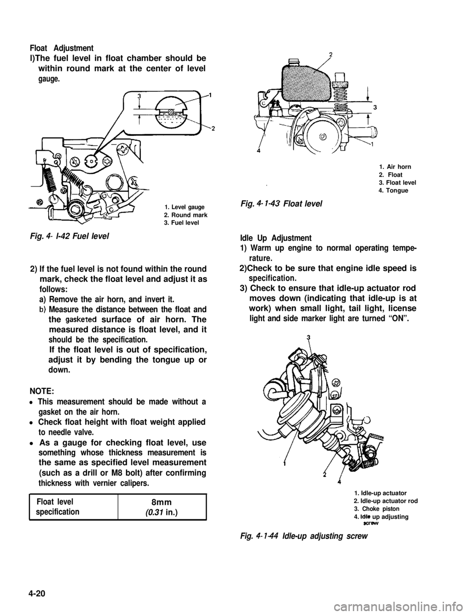
Float Adjustment
l)The fuel level in float chamber should be
within round mark at the center of level
gauge.
1. Level gauge
2. Round mark3. Fuel level
Fig. 4- l-42 Fuel level
2) If the fuel level is not found within the round
mark, check the float level and adjust it as
follows:
a) Remove the air horn, and invert it.
b) Measure the distance between the float and
the gasketed surface of air horn. The
measured distance is float level, and it
should be the specification.
If the float level is out of specification,
adjust it by bending the tongue up or
down.
NOTE:
l This measurement should be made without a
gasket on the air horn.
l Check float height with float weight applied
to needle valve.
l As a gauge for checking float level, use
something whose thickness measurement is
the same as specified level measurement
(such as a drill or M8 bolt) after confirming
thickness with vernier calipers.
Float level8mm
specification(0.31 in.)
.
Fig. 4- l-43 Float level
1. Air horn
2. Float
3. Float level
4. Tongue
Idle Up Adjustment
1) Warm up engine to normal operating tempe-
rature.
2)Check to be sure that engine idle speed is
specification.
3) Check to ensure that idle-up actuator rod
moves down (indicating that idle-up is at
work) when small light, tail light, license
light and side marker light are turned “ON”.
1. Idle-up actuator
2. Idle-up actuator rod
3. Choke piston
4. Idle up adjustingsorew
Fig. 4- l-44 Idle-up adjusting screw
4-20
Page 136 of 962
4) With lights (head light) turned “ON”, check
engine rpm (idle-up speed). Be sure that
heater fan, rear defogger (if equipped), and
air conditioner (if equipped) are all turned
“OFF”.
Idle-up speed900 - 1,000 r/min.
If idle-up speed is not within specification,
adjust by turning adjusting screw.
5) After idle-up adjustment, check to ensure that
idle-up adjusting screw moves as in step 3)
when only heater fan is operated and then
only rear defogger is operated (small light, tail
light, side marker light and license light should
be “OFF” in this cases).
If found faulty in step 3), check following parts
individually according to each procedure.
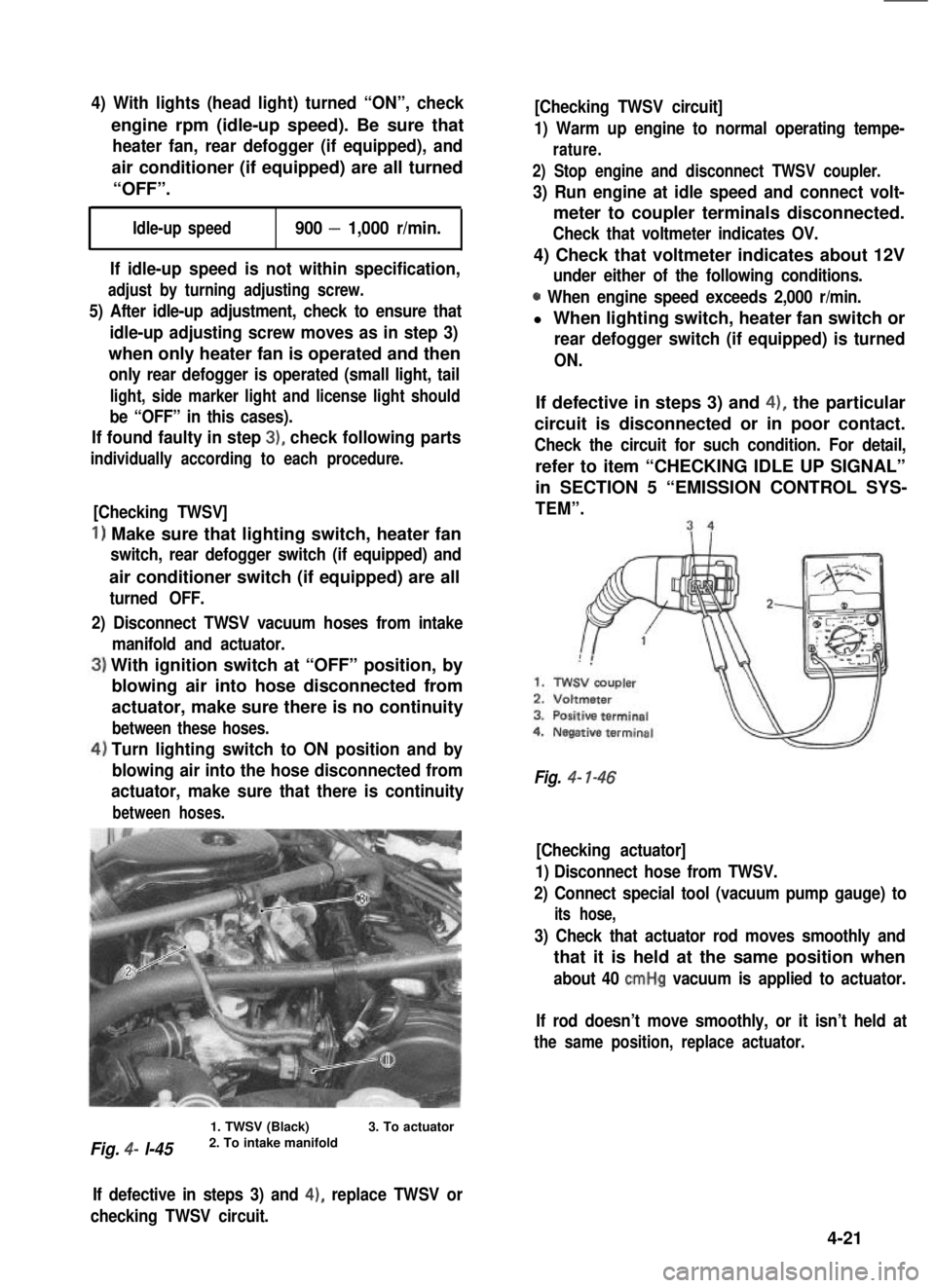
[Checking TWSV]
1) Make sure that lighting switch, heater fan
switch, rear defogger switch (if equipped) and
air conditioner switch (if equipped) are all
turned OFF.
2) Disconnect TWSV vacuum hoses from intake
manifold and actuator.
With ignition switch at “OFF” position, by
blowing air into hose disconnected from
actuator, make sure there is no continuity
between these hoses.
Turn lighting switch to ON position and by
blowing air into the hose disconnected from
actuator, make sure that there is continuity
between hoses.
Fig. 4- l-45
1. TWSV (Black)2. To intake manifold3. To actuator
[Checking TWSV circuit]
1) Warm up engine to normal operating tempe-
rature.
2) Stop engine and disconnect TWSV coupler.
3) Run engine at idle speed and connect volt-
meter to coupler terminals disconnected.
Check that voltmeter indicates OV.
4) Check that voltmeter indicates about 12V
under either of the following conditions.
0 When engine speed exceeds 2,000 r/min.
l When lighting switch, heater fan switch or
rear defogger switch (if equipped) is turned
ON.
If defective in steps 3) and 4), the particular
circuit is disconnected or in poor contact.
Check the circuit for such condition. For detail,
refer to item “CHECKING IDLE UP SIGNAL”
in SECTION 5 “EMISSION CONTROL SYS-
TEM”.
Fig. 4- l-46
[Checking actuator]
1) Disconnect hose from TWSV.
2) Connect special tool (vacuum pump gauge) to
its hose,
3) Check that actuator rod moves smoothly and
that it is held at the same position when
about 40 cmHg vacuum is applied to actuator.
If rod doesn’t move smoothly, or it isn’t held at
the same position, replace actuator.
If defective in steps 3) and 4), replace TWSV or
checking TWSV circuit.
4-21
Page 138 of 962
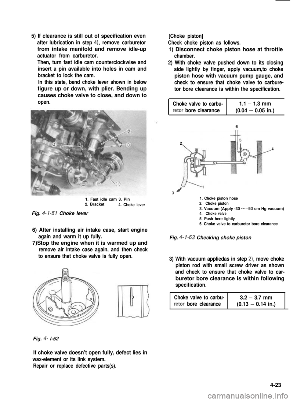
5) If clearance is still out of specification even
after lubrication in step 4), remove carburetor
from intake manifold and remove idle-up
actuator from carburetor.
Then, turn fast idle cam counterclockwise and
insert a pin available into holes in cam and
bracket to lock the cam.
In this state, bend choke lever shown in below
figure up or down, with plier. Bending up
causes choke valve to close, and down to
open.
1. Fast idle cam 3. Pin2. Bracket4. Choke lever
Fig. 4- l-51 Choke lever
6) After installing air intake case, start engine
again and warm it up fully.
7)Stop the engine when it is warmed up and
remove air intake case again, and then check
to ensure that choke valve is fully open.
Fig. 4- l-52
[Choke piston]
Check choke piston as follows.
1) Disconnect choke piston hose at throttle
chamber.
2) With choke valve pushed down to its closing
side lightly by finger, apply vacuum,to choke
piston hose with vacuum pump gauge, and
check to ensure that choke valve to carbure-
tor bore clearance is within the specification.
Choke valve to carbu-1.1 - 1.3 mm
retor bore clearance(0.04 - 0.05 in.)
6
2
4
3/
1. Choke piston hose
2.Chokepiston
3. Vacuum (Apply -30 w-50 cm Hg vacuum)4.Chokevalve
5. Push here lightly
6. Choke valve to carburetor bore clearance
Fig. 4- l-53 Checking choke piston
3) With vacuum appliedas in step 2), move choke
piston rod with small screw driver as shown
and check to ensure that choke valve to car-
buretor bore clearance is within following
specification.
Choke valve to carbu-3.2 - 3.7 mm
retor bore clearance(0.13 - 0.14 in.)
If choke valve doesn’t open fully, defect lies in
wax-element or its link system.
Repair or replace defective parts(s).
4-23