Page 1470 of 1865

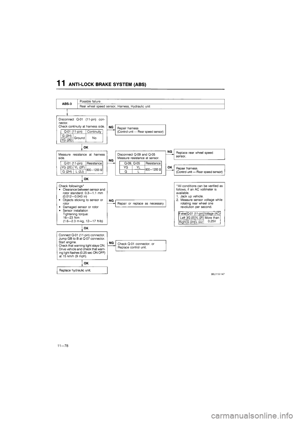
1 1 ANTI-LOCK BRAKE SYSTEM (ABS)
ABS-3
Possible failure
Rear wheel speed sensor, Harness, Hydraulic unit
Disconnect
Q-01
(11-pin)
con-
nector.
Check continuity
at
harness side.
Q-01 (11-pin) Continuity
G (2H) Ground No YG (2E) Ground No
Measure side.
Q-01 (11-pin) Resistance
YG (2E) YL (2F) 800—1200
fi
G (2H)
] L
(2J) 800—1200
fi
OK
Connect Q-01 (11-pin) connector. Jump GB
to B at
Q-07 connector. Start engine.
Check that warning light stays ON. Drive vehicle and check that warn-ing light flashes (0.25 sec ON OFF) at
15
km/h
(9
mph).
NG
Repair harness (Control unit
—
Rear speed sensor)
OK
resistance
at
harness
NG
Disconnect Q-09 and Q-05 Measure resistance
at
sensor.
Q-09, Q-05 Resistance
YG YL 800-1200
0
G L 800-1200
0
OK
Check followings* • Clearance between sensor and rotor standard: 0.3—1.1
mm
(0.012-0.043
in)
• Objects sticking
to
sensor
or
rotor
• Damaged sensor
or
rotor
• Sensor installation Tightening torque: 16-23 N-m
(1.6—2.3 m-kg, 12—17 ft-lb)
NG
Repair
or
replace
as
necessary
NG
Check Q-01 connector. Replace control unit.
or
OK
Replace hydraulic unit,
Replace rear wheel speed
sensor.
OK
Repair harness.
(Control unit
—
Rear speed sensor)
* All conditions can
be
verified
as
follows,
if an AC
voltmeter
is
available. 1. Jack
up
vehicle. 2. Measure sensor voltage while rotating rear wheel
one
revolution
per
second.
fi
wheel Q-01 (11-pin) Voltaqe (AC)
Left |YG (2E) YL (2F) More than 0.25V Right G (2H) L(2J)
More than 0.25V
86U11X-147
11-78
Page 1594 of 1865
SIDE
PROTECTOR MOLDING
1
4
Removal
1. Using a screwdriver or knife, twist the molding end,
being careful not to damage the painted surface,
and separate the adhesive for 20—30 mm
(0.79—1.18 in).
2. Pull the separated portion to remove it.
3. Use a knife to remove any adhesive remaining on
the body or molding.
Note
Remove as much adhesive as possible with-
out damaging the painted surface.
7BU14X-034
7BU14X-035
7BU14X-036
4. If the adhesive is difficult to remove, soften it with
a hot air blower.
Installation
1. Remove any grease or dirt from the molding adhe-
sion surface and the body surface.
2. Mark the installation position on the body with
masking tape.
3. Attach double-sided adhesive tape to the molding
adhesion surface.
4. Align the molding on the body, and attach it se-
curely.
Note
Adhesion conditions deteriorate if air temper-
ature is 20°C (68°F) or less; heating of the
body is thus recommended.
7BU14X-037
14—43
Page 1684 of 1865

METER 15
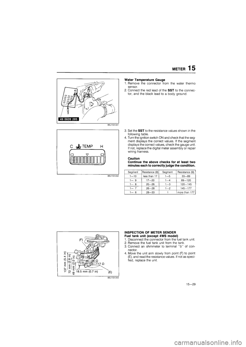
Water Temperature Gauge
1. Remove the connector from the water thermo
sensor.
2. Connect the red lead of the SST to the connec-
tor, and the black lead to a body ground.
86U15X-041
C -&TEMP H
r
•
|
7 •
V i y
86U15X-042
3. Set the SST to the resistance values shown in the
following table.
4. Turn the ignition switch ON and check that the seg-
ment displays the correct values. If the segment
displays the correct values, check the gauge unit.
If not, replace the digital meter assembly or repair
wiring harness.
Caution
Continue the above checks for at least two
minutes each to correctly judge the condition.
Segment Resistance
(Q)
Segment Resistance
(Q)
1-10
less than
17
1-5
33-89
1-
9
17—20
1-4
89-120
1—
8
20—26
1-3
120-145
1—
7
26-28
1-2
145-177
1-
6
28-33
1
more than
177
INSPECTION OF METER SENDER
Fuel tank unit (except 4WS model)
1. Disconnect the connector from the fuel tank unit.
2. Remove the fuel tank unit from the tank.
3. Connect an ohmmeter to terminal "b" of con-
nector.
4. Move the unit arm slowly from point (F) to point
(E), and read the resistance values. If not as speci-
fied, replace the unit.
86U15X-043
15—29
Page 1701 of 1865

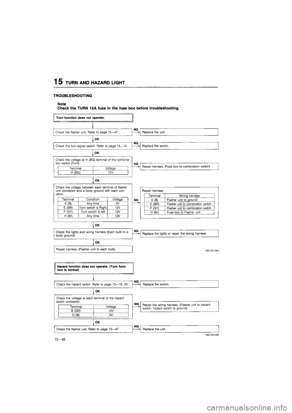
1 5 TURN AND HAZARD LIGHT
TROUBLESHOOTING
Note
Check the TURN 15A fuse in the fuse box before troubleshooting.
Terminal Voltage
H (BG) 12V
OK
Check the voltage between each terminal
of
flasher unit connector and
a
body ground with each con-dition.
Terminal Condition Voltage
A(B) Any time OV
E (BR) Turn switch
is
Riaht 12V
F (GY) Turn switch
is
left 12V
H (Br) Anv time 12V
OK
Turn function does not operate.
Check the flasher unit. Refer
to
page 15—47
OK
Check the turn signal switch. Refer
to
page 15—14
OK
NG
NG
Check the voltage
at H
(BG) terminal
of
the combina-tion switch (Turn).
Replace the unit.
Replace the switch.
NG
Repair harness. (Fuse box
to
combination switch)
Repair harness.
NG
Terminal Wiring harness
A (B) Flasher unit
to
ground
E (BR) Flasher unit
to
combination switch
F (GY) Flasher unit
to
combination switch
H (Bri Fuse box
to
Flasher unit
Check the lights and wiring harness (Each bulb
to a
body ground)
NG
Replace the lights
or
repair the wiring harness.
OK
Repair harness. (Flasher unit
to
each bulb)
76G15X-045
Hazard function does not operate. (Turn func-tion is normal)
Check the hazard switch. Refer
to
page 15—19,
20
OK
NG
Replace the switch.
Check the voltage
at
each terminal
of
the hazard
switch connector.
Terminal Voltage
B (GR) 12V
D (B) OV
15-46
NG
Repair the wiring harness. (Flasher unit
to
hazard
switch, hazard switch
to
ground)
OK
Check the flasher unit. Refer
to
page 15—47
NG
Replace the unit.
76G15X-046
Page 1746 of 1865

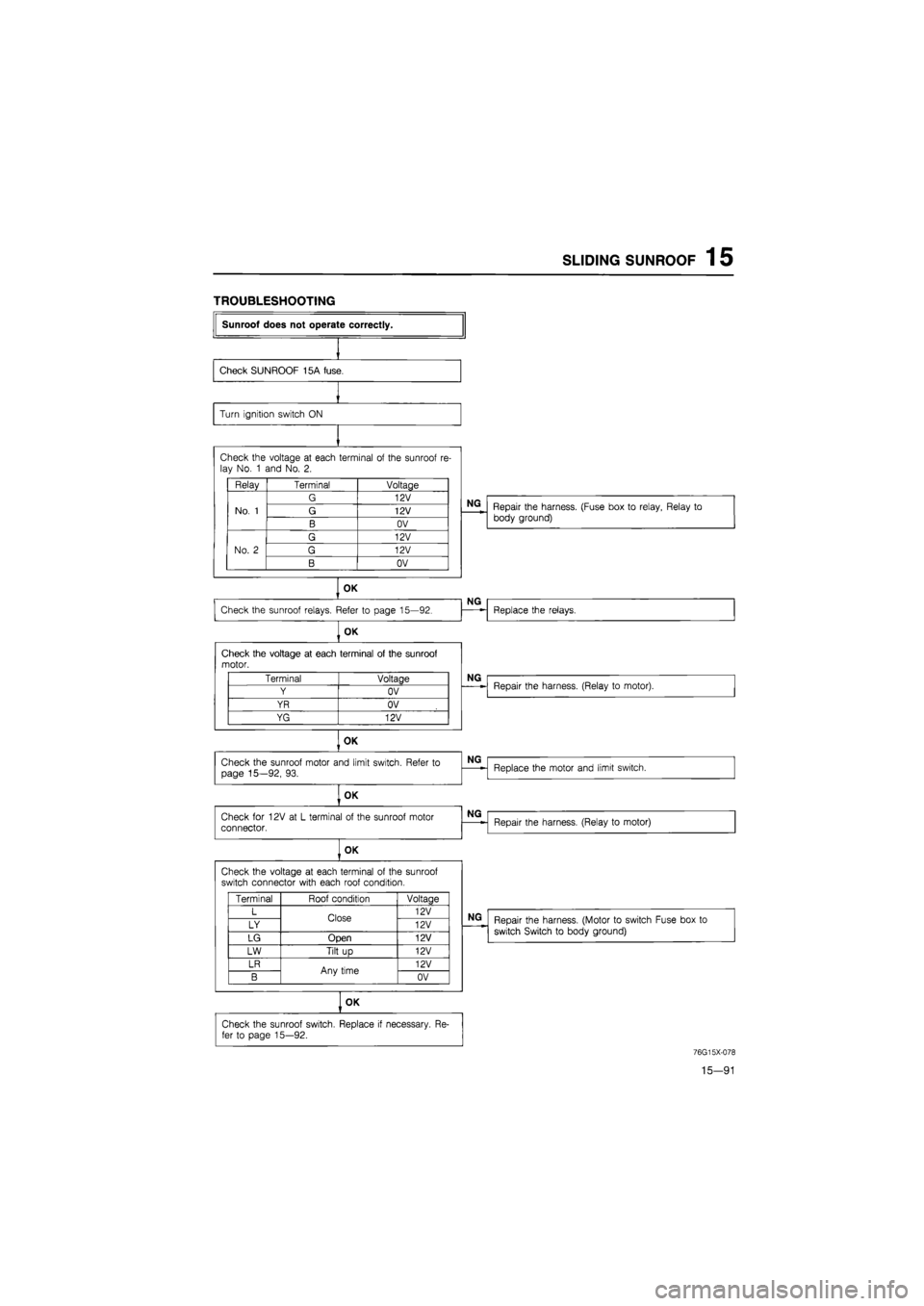
SLIDING SUNROOF 1 5
TROUBLESHOOTING
Sunroof does not operate correctly.
Check SUNROOF 15A fuse.
Turn ignition switch
ON
Check the voltage
at
each terminal
of
the sunroof
re-
lay No.
1
and No.
2.
Relay Terminal Voltage
No.
1
G 12V
No.
1
G 12V No.
1
B OV
No.
2
G 12V
No.
2
G 12V No.
2
B OV
OK
Check the sunroof relays. Refer
to
page 15—92.
OK
Check the voltage
at
each terminal
of
the sunroof motor.
OK
Check the sunroof motor and limit switch. Refer
to
page 15—92,
93.
OK
Check
for
12V
at L
terminal
of
the sunroof motor connector.
OK
Check the voltage
at
each terminal
of
the sunroof switch connector with each roof condition.
OK
Terminal Voltage
Y OV
YR OV
YG 12V
Terminal Roof condition Voltaae
L Close 12V
LY Close 12V
LG Open 12V
LW Tilt
up
12V
LR Any time 12V
B Any time OV
Check the sunroof switch. Replace
if
necessary.
Re-
fer
to
page 15—92.
NG
Repair the harness. (Fuse box
to
relay, Relay
to
body ground)
NG
Replace the relays.
NG
Repair the harness. (Relay
to
motor).
NG
Replace the motor and limit switch.
NG
Repair the harness. (Relay
to
motor)
NG
Repair the harness. (Motor
to
switch Fuse box
to
switch Switch
to
body ground)
76G15X-078
15—91
Page 1761 of 1865
1 5 POWER DOOR LOCK
TROUBLESHOOTING
Terminal Voltage
WG 12V
B OV
Check the voltage
at GB
terminal
of
the power door lock relay with each switch condition.
Terminal Condition Voltage
GB Lock 12V GB Unlock OV
OK
Check the voltage
at R
and
G
terminal
of
the power door lock relay with each switch condition.
Terminal Condition Voltaae
R Lock OV R Unlock 12V
G Lock 12V G Unlock OV
Power door lock does not operate.
Check DOOR LOCK 30A fuse.
OK
NG
Short circuit.
Check the voltage
at
each terminal
of
the power door lock relay connector.
NG
Repair the harness. (Fuse box
to
relay, Relay
to
ground)
OK
Check the power door lock switch. Refer
to
page 15-107.
OK
NG
Replace the switch.
NG
Repair the harness. (Door lock switch
to
relay)
NG
Replace the door lock relay.
OK
Check the power door lock motor. Refer
to
page
15-107.
OK
Repair the harness. (Relay
to
each motors)
NG
Replace the door lock motor.
76G15X086
15—106
Page 1770 of 1865
AUDIO SYSTEM 1 5
Power Antenna Circuit
86U15X-194
inspection Of Power Antenna Relay
1. Check the voltage at each terminal of the relay con-
nector harness side with each condition.
Terminal Condition Voltage
LW Ignition switch ACC 12V
BY Ignition switch
ON
12V
LgW Ignition switch ACC and radio
power switch
ON
OV
LR Any time 12V
76G15X-096
86U15X-196
If not, repair the harness.
2. Turn the ignition switch on, and check the opera-
tion of the power antenna with each condition.
Condition Antenna operation
GW wire
is
connected
to a
body ground Rises
GW wire
is
not connected to
a
body ground Goes down
If the power antenna does not operate, replace the
power antenna relay or power antenna motor.
15—115
Page 1780 of 1865
![MAZDA 626 1987 Workshop Manual
HEATER 15
Effl
k /
Voltmeter
86U15X-214
d I
k J X
S3
Voltmeter
86U15X-215
[ I H
k J X /
xj;
iD5F]H|j
ll iE;G Ll.i.i..
Ohmmeter
86U15X-216
d C
•W
©
i IL i
X / X
Qi ! i
+
MAZDA 626 1987 Workshop Manual
HEATER 15
Effl
k /
Voltmeter
86U15X-214
d I
k J X
S3
Voltmeter
86U15X-215
[ I H
k J X /
xj;
iD5F]H|j
ll iE;G Ll.i.i..
Ohmmeter
86U15X-216
d C
•W
©
i IL i
X / X
Qi ! i
+](/manual-img/28/57059/w960_57059-1779.png)
HEATER 15
Effl
k /
Voltmeter
86U15X-214
d I
k J X
S3
Voltmeter
86U15X-215
[ I H
k J X /
xj;
iD5F]H|j
ll iE;G Ll.i.i..
Ohmmeter
86U15X-216
d C
•W
©
i IL i
X / X
Qi ! i
+
u
Voltmeter
3. Connect a resistance (at least 1 kfi) between d ter-
minal and D terminal, and check the voltage be-
tween D terminal and L terminal using a voltmeter.
Terminals Voltage
D
- L
Less than
1V
4. Connect a resistance (at least 1 kfl) between d ter-
minal and A terminal, and check the voltage be-
tween A terminal and L terminal using a voltmeter.
Terminal Voltage
A - L Less than 1V
5. Check for continuity between each terminal with
following condition using an ohmmeter.
Condition Terminals Continuity
Push the VENT switch J
- L
Yes
Push the B/L switch G
- L
Yes
Push the HEAT switch H
— L
Yes
Push the H/D switch E
- L
Yes
Push the DEF switch F
- L
Yes
Checking Air Mix Control Circuit
1. Connect a resistance (at least 1 kfl) between Q ter-
minal and T terminal.
Set temperature control lever to center position be-
tween MAX HOT and MAX COLD.
Connect a jumper wire between V terminal and U
terminal, and check the voltage between each ter-
minals.
Terminals Voltage
T
- L
Approx.
12V
Q
- L
Less than
1V
86U15X-217
15—125