Page 1796 of 1865
COMPRESSOR 16
69G16X-026
M10X1.25^45
Low-pressure x pressure
hose hose Compressor
COMPRESSOR
ON-VEHICLE INSPECTION
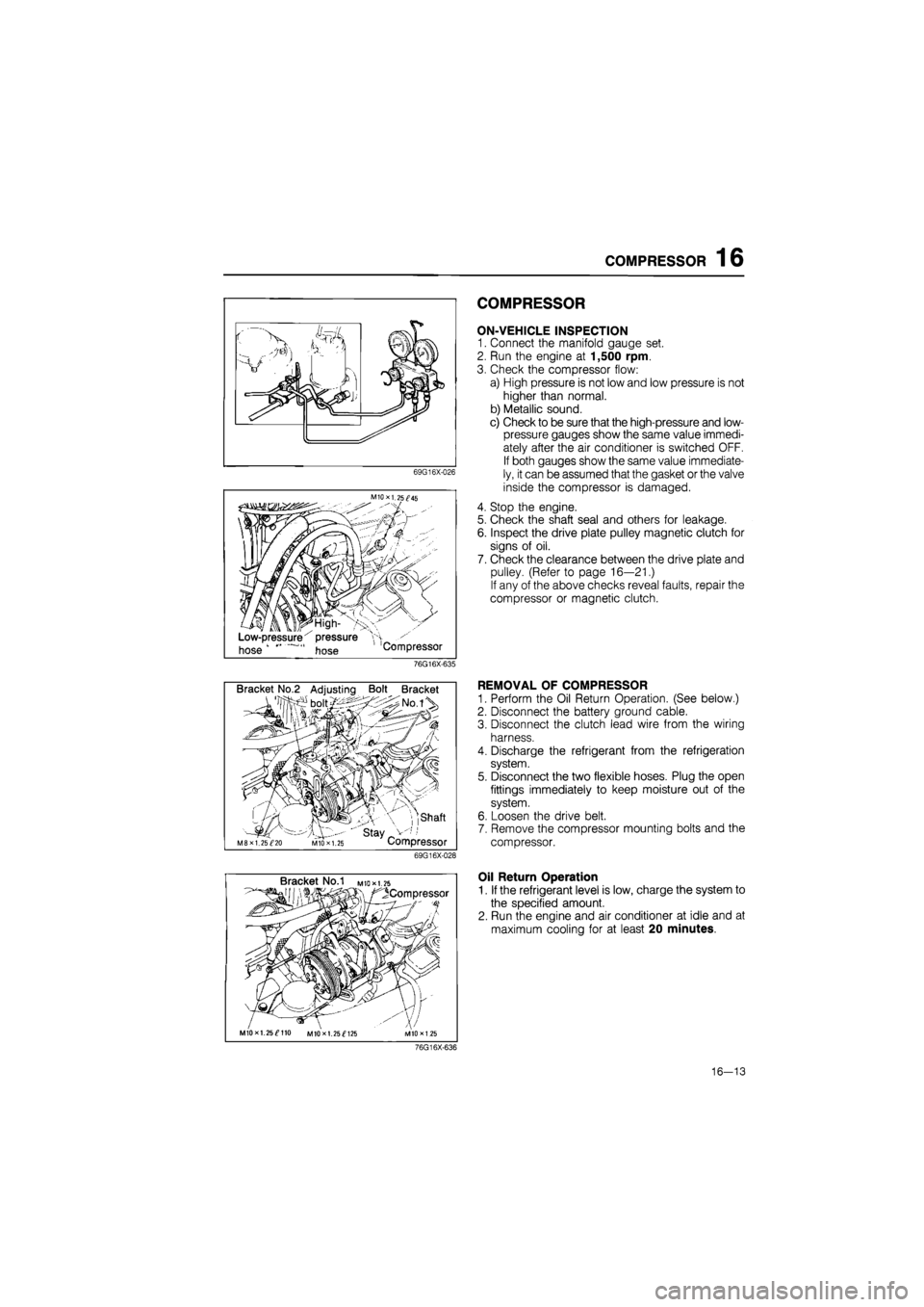
1. Connect the manifold gauge set.
2. Run the engine at 1,500 rpm.
3. Check the compressor flow:
a) High pressure is not low and low pressure is not
higher than normal.
b) Metallic sound.
c) Check to be sure that the high-pressure and low-
pressure gauges show the same value immedi-
ately after the air conditioner is switched OFF.
If both gauges show the same value immediate-
ly, it can be assumed that the gasket or the valve
inside the compressor is damaged.
4. Stop the engine.
5. Check the shaft seal and others for leakage.
6. Inspect the drive plate pulley magnetic clutch for
signs of oil.
7. Check the clearance between the drive plate and
pulley. (Refer to page 16—21.)
If any of the above checks reveal faults, repair the
compressor or magnetic clutch.
76G16X-635
Bracket No.2 Adjusting Bolt Bracket
, ,shaft
' stay _ M8XI. 25^20 MIO X 1.25 Compressor
69G16X-028
REMOVAL OF COMPRESSOR
1. Perform the Oil Return Operation. (See below.)
2. Disconnect the battery ground cable.
3. Disconnect the clutch lead wire from the wiring
harness.
4. Discharge the refrigerant from the refrigeration
system.
5. Disconnect the two flexible hoses. Plug the open
fittings immediately to keep moisture out of the
system.
6. Loosen the drive belt.
7. Remove the compressor mounting bolts and the
compressor.
Bracket No.1 M
to* 1.25
^Compressor
MIOxl. 25^110 MIOxl. 25^125
Oil Return Operation
1. If the refrigerant level is low, charge the system to
the specified amount.
2. Run the engine and air conditioner at idle and at
maximum cooling for at least 20 minutes.
76G16X-636
16—13
Page 1806 of 1865
COMPRESSOR 16
Bracket No/I mio*i.75
/^Compressor
V'
MIOxl.25^110 M10X1.25^125 M1DX1.2S
76G16X-618
Bracket No.2 Adjusting Bolt Bracket
• boit/:> X ;>No.iV
•S3-
f'f
// mi
I 1 I 1 Shaft
M8 x 1.25^20 • ' Stay V-;,' M10X1.25 Compressor 76G16X-619
V belt Turn the adjusting bolt
Compressor Adjusting bolt
76G16X-620
MIOxl. 25^45
Low-pressure' pressure "H
hose hose Compressor
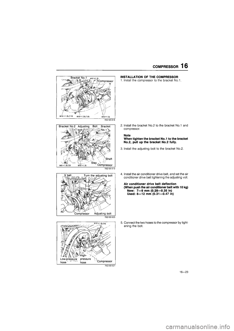
INSTALLATION OF THE COMPRESSOR
1. Install the compressor to the bracket No.1.
2. Install the bracket No.2 to the bracket No.1 and
compressor.
Note
When tighten the bracket No.1 to the bracket
No.2, pull up the bracket No.2 fully.
3. Install the adjusting bolt to the bracket No.2.
4. Install the air conditioner drive belt, and set the air
conditioner drive belt tightening the adjusting volt.
Air conditioner drive belt deflection
(When push the air conditioner belt with 10 kg)
New: 7—9 mm (0.28—0.35 in)
Used: 8—12 mm (0.31—0.47 in)
5. Connect the two hoses to the compressor by tight-
ening the bolt.
76G16X-621
16—23
Page 1807 of 1865
16 CONDENSER
CONDENSER
ON-VEHICLE INSPECTION
1. Check the condenser fins for blockage or damage.
If the fins are clogged, clean them with compressed air.
If the fins are bent, straighten them with a screwdriver or pair of pliers.
2. Check the condenser fittings for leakage.
Repair or replace, if necessary.
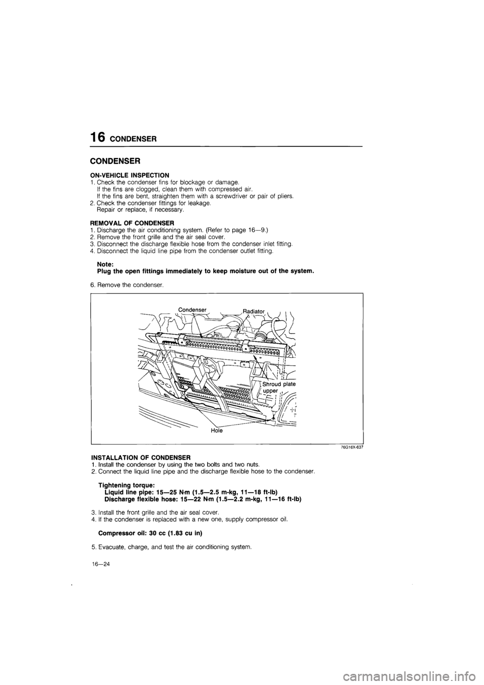
REMOVAL OF CONDENSER
1. Discharge the air conditioning system. (Refer to page 16—9.)
2. Remove the front grille and the air seal cover.
3. Disconnect the discharge flexible hose from the condenser inlet fitting.
4. Disconnect the liquid line pipe from the condenser outlet fitting.
Note:
Plug the open fittings immediately to keep moisture out of the system.
6. Remove the condenser.
Condenser Radiator
Hole
76G16X-637
INSTALLATION OF CONDENSER
1. Install the condenser by using the two bolts and two nuts.
2. Connect the liquid line pipe and the discharge flexible hose to the condenser.
Tightening torque:
Liquid line pipe: 15—25 Nm (1.5—2.5 m-kg, 11—18 ft-lb)
Discharge flexible hose: 15—22 N-m (1.5—2.2 m-kg, 11—16 ft-lb)
3. Install the front grille and the air seal cover.
4. If the condenser is replaced with a new one, supply compressor oil.
Compressor oil: 30 cc (1.83 cu in)
5. Evacuate, charge, and test the air conditioning system.
16—24
Page 1808 of 1865
RECEIVER-DRIER 16
RECEIVER-DRIER
ON-VEHICLE INSPECTION
1. Use a leak detector to check the sight glass, the
fusible plug, and the fittings for leakage.
Repair or replace, if necessary.
2. Check the receiver-drier for clogging.
a) Run the engine at fast idle with the air conditioner
on.
b) Check both inlet and outlet temperatures.
If there is a great difference between the two tem-
peratures, replace the receiver-drier.
76G16X-622
Receiver-drier
Condenser bolt
76G16X-638
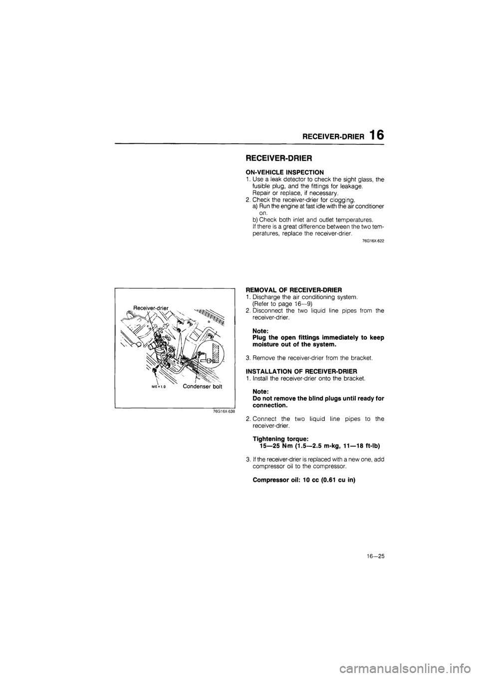
REMOVAL OF RECEIVER-DRIER
1. Discharge the air conditioning system.
(Refer to page 16—9)
2. Disconnect the two liquid line pipes from the
receiver-drier.
Note:
Plug the open fittings immediately to keep
moisture out of the system.
3. Remove the receiver-drier from the bracket.
INSTALLATION OF RECEIVER-DRIER
1. Install the receiver-drier onto the bracket.
Note:
Do not remove the blind plugs until ready for
connection.
2. Connect the two liquid line pipes to the
receiver-drier.
Tightening torque:
15—25 N m (1.5—2.5 m-kg, 11—18 ft-lb)
3.
If
the receiver-drier is replaced with a new one, add
compressor oil to the compressor.
Compressor oil: 10 cc (0.61 cu in)
16-25
Page 1809 of 1865
16 COOLING UNIT
COOLING UNIT
ON-VEHICLE INSPECTION OF EXPANSION
VALVE
1. Connect the manifold gauge set to the gauge fit-
tings on the low- and high-pressure pipes.
2. Operate the engine at 1,500 rpm and the air con-
ditioner at MAX. COOLING.
3. Check the low and high pressures.
Normal pressures are:
Low: 197—294 kPa
(2—3 kg/cm2, 28—43 psi)
High: 1472—1765 kPa
(15—18 kg/cm2, 210—260 psi)
If pressure is not as specified, replace the expansion
valve.
76G16X-623
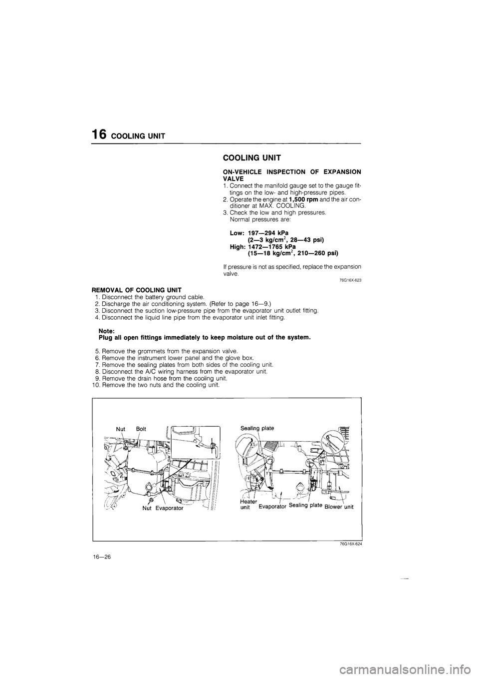
REMOVAL OF COOLING UNIT
1. Disconnect the battery ground cable.
2. Discharge the air conditioning system. (Refer to page 16—9.)
3. Disconnect the suction low-pressure pipe from the evaporator unit outlet fitting.
4. Disconnect the liquid line pipe from the evaporator unit inlet fitting.
Note:
Plug all open fittings immediately to keep moisture out of the system.
5. Remove the grommets from the expansion valve.
6. Remove the instrument lower panel and the glove box.
7. Remove the sealing plates from both sides of the cooling unit.
8. Disconnect the A/C wiring harness from the evaporator unit.
9. Remove the drain hose from the cooling unit.
10. Remove the two nuts and the cooling unit.
76G16X-624
16-26
Page 1812 of 1865
REFRIGERANT LINES 1 6
REFRIGERANT LINES
ON-VEHICLE INSPECTION
1. Check all piping connections for leakage by using a leak detector. Replace if necessary.
2. Check that the hose and pipe clamps are not loose.
Tighten or replace, if necessary.
REPLACEMENT OF REFRIGERANT LINES
1. Discharge the air conditioning system. (Refer to page 16—9)
2. Replace the faulty pipe or hose.
Note:
Plug all open fittings immediately to keep moisture out of the system.
Tightening torque (fittings):
Location Tightening torque
© 10—20 N m (1.0—2.0 m-kg, 7.2—14.4 ft-lb)
© 15—25 Nm (1.5—2.5 m-kg, 10.8—18.0 ft-lb)
© 20—29 Nm (2.0—3.0 m-kg, 14.4—21.6 ft-lb)
3. Evacuate, charge, and test the air conditioning system. (Refer to page 16—9.)
76G16X-628
16—29
Page 1813 of 1865
1 6 A/C RELAY
A/C RELAY
REMOVAL OF RELAY
1. Disconnect the negative battery cable.
2. Disconnect the wire harness connector
3. Remove the relay from the seal plate.
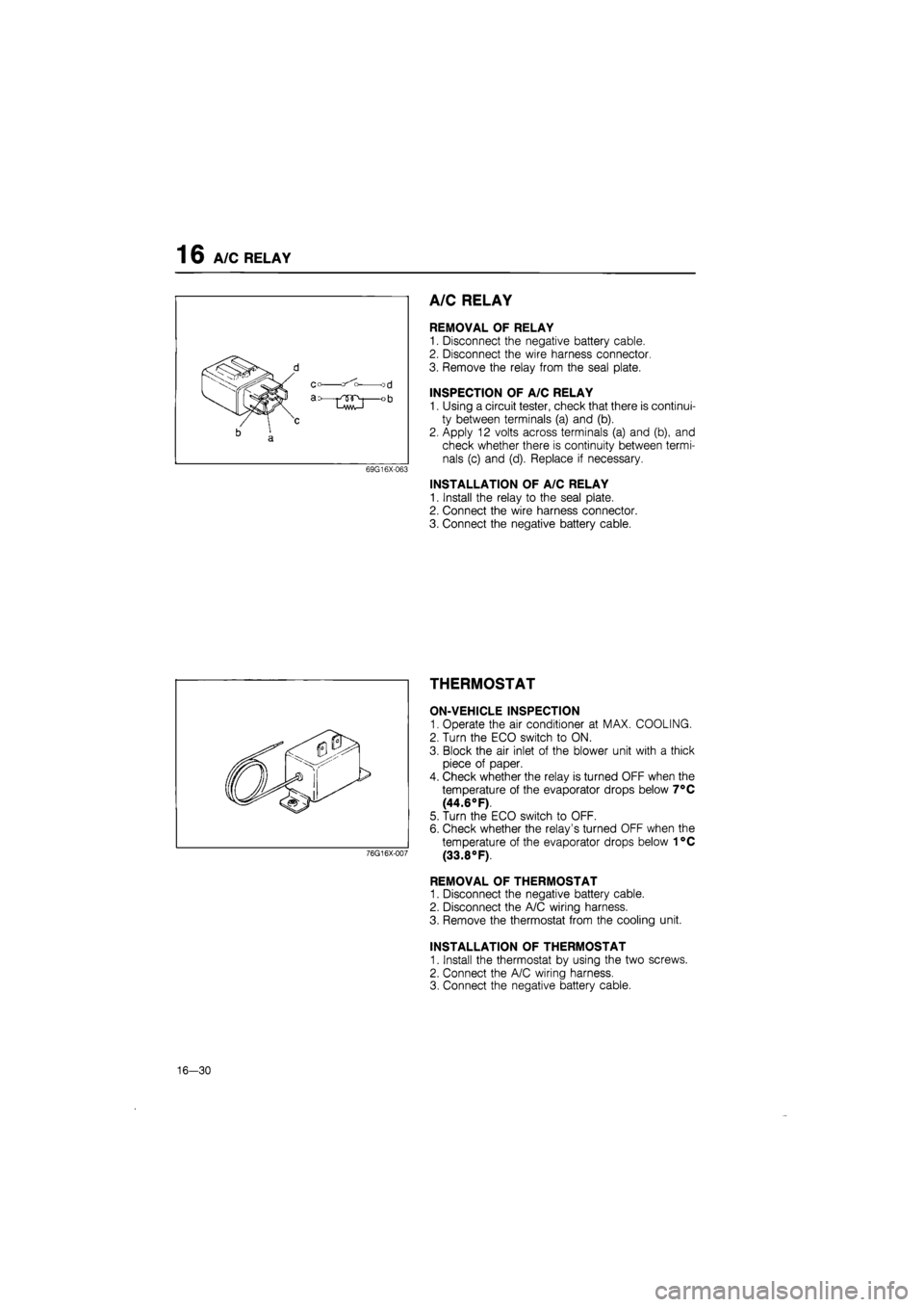
INSPECTION OF A/C RELAY
1. Using a circuit tester, check that there is continui-
ty between terminals (a) and (b).
2. Apply 12 volts across terminals (a) and (b), and
check whether there is continuity between termi-
nals (c) and (d). Replace if necessary.
INSTALLATION OF A/C RELAY
1. Install the relay to the seal plate.
2. Connect the wire harness connector.
3. Connect the negative battery cable.
THERMOSTAT
ON-VEHICLE INSPECTION
1. Operate the air conditioner at MAX. COOLING.
2. Turn the ECO switch to ON.
3. Block the air inlet of the blower unit with a thick
piece of paper.
4. Check whether the relay is turned OFF when the
temperature of the evaporator drops below 7°C
(44.6°F).
5. Turn the ECO switch to OFF.
6. Check whether the relay's turned OFF when the
temperature of the evaporator drops below 1°C
(33.8°F).
REMOVAL OF THERMOSTAT
1. Disconnect the negative battery cable.
2. Disconnect the A/C wiring harness.
3. Remove the thermostat from the cooling unit.
INSTALLATION OF THERMOSTAT
1. Install the thermostat by using the two screws.
2. Connect the A/C wiring harness.
3. Connect the negative battery cable.
76G16X-007
16-30