1987 MAZDA 626 air condition
[x] Cancel search: air conditionPage 674 of 1865

TROUBLESHOOTING GUIDE 4D
TROUBLESHOOTING GUIDE
Condition Condition Cause Remedy
Hard starting Fuel filter
Clogged Replace
Water or air in filter Repair
Fuel injection pump Faulty fuel cut solenoid Replace Incorrect injection timing Adjust
Air in pump Bleed
Faulty pump Replace
Fuel injection nozzle Seized needle valve Replace
Fuel dripping from nozzle Replace Incorrect valve opening pressure Adjust
Faulty glow plug Replace
Faulty cold start device Adjust or replace
Faulty supercharging system Refer to page 4D—10
Rough idle Fuel filter (Refer to "Hard starting") Fuel injection pump (Refer to "Hard starting")
Fuel injection nozzle
Seized needle valve Replace
Incorrect valve opening pressure Adjust
Improper mounting to nozzle holder Repair
Leakage of nozzle holder copper washer Replace
Fuel injection pipe Cranks Replace
Leaking from joint Repair
Improper idle speed adjustment Adjust
Engine knocking Incorrect injection timing Adjust
Low quality fuel Replace
Incorrect injection nozzle opening pressure Ajust
Seized injection nozzle needle valve Replace
Fuel dripping from injection nozzle Replace
Faulty supercharging system Refer to page 4D—10
High fuel Fuel injection pump consumption Incorrect injection timing Adjust consumption High idle speed Adjust, Inspect the dashpot
Fuel injection nozzle Incorrect valve opening pressure Repair
Fuel dripping from nozzle Replace
Leakage of nozzle holder copper washer Replace
Fuel leaking from connection Repair
Clogged fuel filter Replace
Clogged air cleaner Replace
Poor acceleration Fuel injection nozzle (Refer to "Hard starting")
Fuel injection pump (Refer to "Hard starting")
Fuel injection pipe (Refer to "Rough idle") Fuel filter (Refer to "Hard starting") Clogged air cleaner Clean or replace
Faulty supercharging system Refer to page 4D—10
Excessive exhaust Clogged air cleaner Clean or replace
smoke Improper injection timig Adjust
Faulty nozzle or nozzle holder Adjust or replace
Faulty supercharging system Refer to page 4D—10
76G04D-003
4D-3
Page 715 of 1865
SPARK PLUG 5
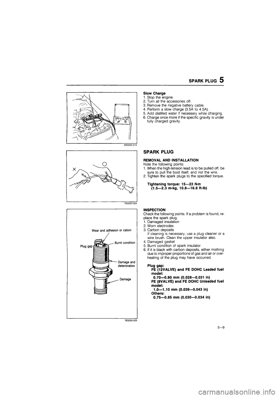
Slow Charge
1. Stop the engine
2. Turn all the accessories off.
3. Remove the negative battery cable.
4. Perform a slow charge (3.5A to 4.5A).
5. Add distilled water if necessary while charging.
6. Charge once more if the specific gravity is under
fully charged gravity.
4BG05X-010
SPARK PLUG
REMOVAL AND INSTALLATION
Note the following points:
1. When the high-tension lead is to be pulled off, be
sure to pull the boot itself, and not the wire.
2. Tighten the spark plugs to the specified torque.
Tightening torque: 15—23 N-m
(1.5—2.3 m-kg, 10.8—16.6 ft-lb)
76G05X-054
Wear and adhesion or cabon
INSPECTION
Check the following points. If a problem is found, re-
place the spark plug.
1. Damaged insulation
2. Worn electrodes
3. Carbon deposits
If cleaning is necessary, use a plug cleaner or a
wire brush. Clean the upper insulator also.
4. Damaged gasket
5. Burnt condition of spark insulator
6. If it is black with carbon deposits, either misfiring
due to improper proportions of gas and air or over-
heating of the plug may have occurred.
Plug gap:
FE (12VALVE) and FE DOHC Leaded fuel
model:
0.70—0.80 mm (0.028—0.031 in)
FE (8VALVE) and FE DOHC Unleaded fuel
model:
1.0—1.10 mm (0.039—0.043 in)
Others:
0.75—0.85 mm (0.030—0.034 in)
76G05X-005
5-9
Page 1123 of 1865
TROUBLESHOOTING
7C
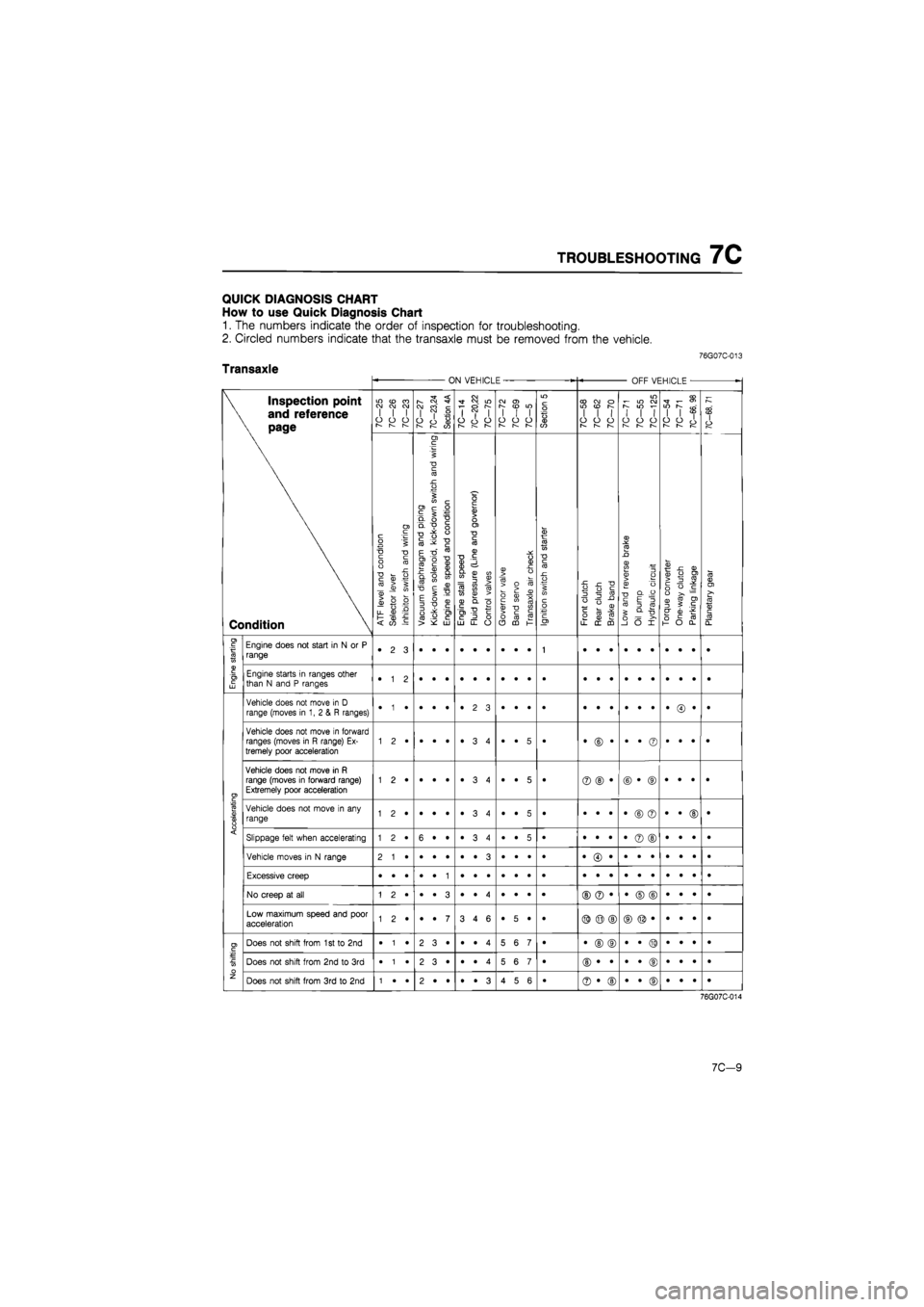
QUICK DIAGNOSIS CHART
How
to use
Quick Diagnosis Chart
1.
The
numbers indicate
the
order
of
inspection
for
troubleshooting.
2. Circled numbers indicate that
the
transaxle must
be
removed from
the
vehicle.
76G07C-013
Transaxle ON VEHICLE OFF VEHICLE
•
\ Inspection point
\
and
reference
\ page
Condition
7C-25
7C-26
7C-23
10—21
7C—23,24
Section
4A
7C-14
7C—20,22
10—lb
10-12 10—69
7C—5
Section
5
7C—58
7C-62
7C-70
7C-71
7C-55
7C-125
7C-54 7C-71
7C-66,
98
7C-68,
71
\ Inspection point
\
and
reference
\ page
Condition
ATF
level
and
condition
Selector
lever
Inhibitor
switch
and
wiring
^
Vacuum
diaphragm
and
piping
|
Kick-down
solenoid,
kick-down
switch
and
wiring
Engine
idle
speed
and
condition
Engine
stall
speed
Fluid
pressure
(Line
and
governor)
Control
valves
Governor
valve
Band
servo
Transaxle
air
check
Ignition
switch
and
starter
Front
clutch
Rear
clutch
Brake
band
Low
and
reverse
brake
Oil
pump Hydraulic
circuit
Torque
converter
One-way
clutch
Parking
linkage
Planetary
gear
I
Engine
starting
Engine does
not
start
in
N or P
range •
2 3
1
Engine
starting
Engine starts
in
ranges other than
N
and P
ranges •
1 2
Accelerating
Vehicle does
not
move
in
D
range (moves
in 1, 2 & R
ranges) •
• •
•
Accelerating
Vehicle does
not
move
in
forward ranges (moves
in R
range)
Ex-
tremely poor acceleration •
• 5
• •
© •
•
• ©
•
• •
•
Accelerating
Vehicle does
not
move
in R
range (moves
in
forward range) Extremely poor acceleration 1
2 •
•
• •
•
3 4
•
• 5
• ©
© •
©
• ©
•
• •
•
Accelerating
Vehicle does
not
move
in any
range 1
2 •
•
• •
•
3 4
•
• 5
• •
• •
•
© ©
•
• ©
•
Accelerating Slippage felt when accelerating 1
2 •
6
• •
•ST
CO
•
•
• 5
• •
• •
•
© ©
•
• •
• Accelerating
Vehicle moves
in
N
range
Accelerating
Excessive creep
Accelerating
No creep
at all
©
© •
•
© ©
•
• •
•
Accelerating
Low maximum speed
and
poor acceleration 1
2 •
•
• 7
3
4 6
•
5 •
• ©
© ©
No shifting
Does
not
shift from
1
st to 2nd
•
1 •
2
3 •
•
• 4
5
6 7
• •
© ©
•
• ©
•
• •
•
No shifting
Does
not
shift from
2nd to 3rd
•
1 •
2
3 •
•
• 4
5
6 7
•
No shifting
Does
not
shift from
3rd to 2nd
1
• •
2
• •
•
• 3
4
5 6
• ©
• ©
•
• ©
•
• •
•
76G07C-014
7C-9
Page 1124 of 1865
7C TROUBLESHOOTING
ON VEHICLE OFF VEHICLE
-
\ Inspection point
\ and reference
\ page
Condition
LO
(O
CO CJ OJ CM I
I I
O
O
CJ
r-~
r—
7C-27
7C—23,24
Section
4A
7C—14
7C—20,22
7C-75
CO
O)
I
I I
o
o o
r—
r—
Section
5
CO CO
o
WON I
I I
o
o o
1— 1—
m i-
in co
S
IO
i-
1
1 1
o
o o
—
I—
7C—54
7C-71
7C-66,
98
7C—68,
71
\ Inspection point
\ and reference
\ page
Condition
A.TF
level
and
condition
Selector
lever
Inhibitor
switch
and
wiring
Vacuum
diaphragm
and
piping
Kick-down
solenoid,
kick-down
switch
and
wiring
Engine
idle
speed
and
condition
Engine
stall
speed
Fluid
pressure
(Line
and
governor)
Control
valves
Governor
valve
Band
servo
Transaxle
air
check
Ignition
switch
and
starter
Front
clutch
Rear
clutch
Brake
band
Low
and
reverse
brake
Oil pump Hydraulic
circuit
Torque
converter
One-way
clutch
Parking
linkage
Planetary
gear
No
shifting
Does
not
shift from 2nd
to
1
st or from
3rd to
1
st 1
• •
2
• •
•
• 3
4
5 6
•
No
shifting
Does
not
kick-down when accelerator
is
depressed
in 3rd
within
the
kick-down range 1
• •
3
2*
•
• 4
5
• •
• •
• ©
•
• ©
•
• •
•
No
shifting
Excessive engine speed when accelerated
in 3rd
due
to
delayed kick-down 5
• 6
• ©
• •
•
• ©
•
• •
• No
shifting
Does
not
shift from
3rd to 2nd
on
D to
2
range shift 1
2 •
5
6 •
• ©
• ®
•
• ®
•
• •
•
No
shifting
Does
not
shift from
3rd to 2nd
on
D to 1
range shift 5
7 6
• ©
• ®
•
• ®
•
• •
•
Shift
shock
Excessive
N to
D
range shift shock •
• •
2
• 1
•
3 4
•
• •
• •
© •
•
• •
•
• •
•
Shift
shock
Excessive
1
st
to
2nd shift shock 1
• •
2
• •
3
• 4
•
5 6
• •
• ©
•
• •
•
• •
•
Shift
shock
Excissive 2nd
to 3rd
shift shock •
• •
1
• •
•
2 3
•
4 5
• ©
• ©
Shift
shock
Vehicle braked when shifted from
1
st
to 2nd
Shift
shock
Vehicle braked when shifted from 2nd
to 3rd
1
• •
•
• •
•
• 3
.
2 •
•
Shift
shock
Vehicle braked when shifted
to
R range 1
• •
•
• •
•
• •
•
3 2
• •
© ©
•
• •
•
• ©
•
Shift
shock
Shift shock felt when accelerator
is
released
and
deceleration occurs •
1 •
2
3*
•
4 5
6
• •
• •
• •
•
• ©
•
• *
•
Shift
shock
Excessively large 2nd
to 1st
shift shock
in 1
range 1
• •
2
• •
3
4 5
•
• •
•
Shift
point
Excessively high
1st to 2nd
and 2nd
to
3rd shift 1
• •
2
3 •
•
4 5
6
• •
•
Shift
point
Excessively high
3rd to 2nd
and
2nd to
1
st shift point •
1 •
2
3 •
•
4 5
6
• •
• •
• •
•
• ©
•
• •
•
Shift
point
Kick-down operates
or
engine overruns when depressing
ped-
al
in 3rd
beyond kick-down speed limit
1
2 •
3
• •
•
4 5
6
• 7
•
Shift
sequence
Shifts directly from 1st
to 3rd
1
• •
•
• •
•
• 2
3
• 4
• •
• ©
•
• ©
•
• •
•
Shift
sequence
Shifts from
2nd to 1st or
2nd
to
3rd
in
2
range •
1 •
•
• •
•
2 3
•
• •
•
7C-10
Page 1125 of 1865
TROUBLESHOOTING
7C
ON VEHICLE -OFF VEHICLE
-
\ Inspection point
\
and
reference
\ page
Condition
in cd
ra
CM CM CM
I
I I
o
o o
I—
r~—
r—
7C—27
7C—23,24
Section
4A
7C—14
7C—20,22
7C-75
CM
0>
[—
CO
LO I
I I
O
O O
r^ r—
Section
5
CD CM
O
in (D
s
I
I I
o
o o
r—
r^
w
CM
r-
m f-
I
I I
o
o o
r-— I—
r-—
7C—54
7C-71
7C—66,
98
7C-68,
71 \ Inspection point
\
and
reference
\ page
Condition
ATR
level
and
condition
Selector
lever
Inhibitor
switch
and
wiring
Vacuum
diaphragm
and
piping
Kick-down
solenoid,
kick-down
switch
and
wiring
Engine
idle
speed
and
condition
Engine
stall
speed
Fluid
pressure
(Line
and
governor)
Control
valves
Governor
valve
Band
servo
Transaxle
air
check
Ignition
switch
and
starter
Front
clutch
Rear
clutch
Brake
band
Low
and
reverse
brake
Oil
pump
Hydraulic
circuit
Torque
converter
One-way
clutch
Parking
linkage
Planetary
gear
Snift
sequence
Shifts from
1st to
2nd
or
2nd
to
3rd
in 1
range
Slipping
Practically
no
shift shock,
or
slip-page while 1st
to
2nd shifting 1
2 •
3
• •
•
4 5
•
7 6
• •
• ©
•
• ©
•
• •
•
Slipping
Pracatically
no
shift shock
or
slip-page while 2nd
to
3rd shifting 1
2 •
3
• •
•
4 5
•
7 6
•
Slipping
No shift shock
or
engine runaway
in 1 to 2
range shift 1
2 •
3
• 4
5
• 6
•
• 7
• •
• ©
•
© •
•
• •
•
Slipping
Engine runaway
or
slip when shifting
3rd to 2nd
1
• •
2
• •
•
3 4
•
5 6
• ®
• ©
•
• ®
•
• •
•
Slipping
Slippage evident when vehicle starts moving 1
2 •
5
• •
•
3 4
•
• 6
• •
• •
•
® ©
•
• •
•
Noise
Transaxle noisy
in P and N
range
Noise
Transaxle noisy
in D, 2, 1 and
R ranges •
(D •
•
© •
•
© •
©
Others
No engine brake
in 1
range •
1 •
•
• •
•
2 3
•
• 4
• •
• •
©
• ©
•
• •
•
Others
Vehicle moves
in P
range
or
parking gear
not
disengaged when
P
range disengaged
•
Others
Transaxle overheats 3
4 5
•
2 6
• ®
©
(D ©
© ©
©
• •
©
Others
White smoke from exhaust while running 1
• •
2
• •
3
4 5
•
• 6
• ®
© ©
©
© ©
©
• •
@
Others
Abnormal odor from
oil
level gauge pipe ©
® ©
©
© ®
©
• •
©
76G07C-016
Differential
Problem Probable Cause Remedy Page
Noise Insufficient fluid Add 7C—25
Low fluid quality Replace with specified
ATF
7C-25
Worn bearing Adjust
or
replace 7C-79
Contact surface
of
gears worn Replace 7C-79
Tooth surface
of
gears damaged Replace 7C-79
Contaminated
ATF
Repair
or
replace 7C-25
Differential gear damaged, excessive backlash Replace 7C-79
Excessive bearing preload Adjust 7C—94
76G07C-017
7C—11
Page 1419 of 1865
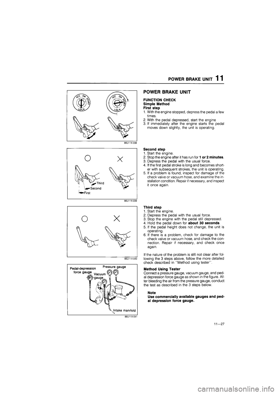
POWER BRAKE UNIT 1 1
86U11X-038
0
o
X
\ V^ Third
Second
^ First
86U11X-039
O X
fiSy
V
86U11X-040
Pedal-depression Pre!tur!9au9e
force gauge
^Intake manifold
86U11X-041
POWER BRAKE UNIT
FUNCTION CHECK
Simple Method
First step
1. With the engine stopped, depress the pedal a few
times.
2. With the pedal depressed, start the engine
3. If immediately after the engine starts the pedal
moves down slightly, the unit is operating.
Second step
1. Start the engine.
2. Stop the engine after it has run for
1
or 2 minutes.
3. Depress the pedal with the usual force.
4.
If
the first pedal stroke is long and becomes short-
er with subsequent strokes, the unit is operating.
5. If a problem is found, inspect for damage of the
check valve or vacuum hose, and examine the in-
stallation condition. Repair if necessary, and inspect
it once again.
Third step
1. Start the engine.
2. Depress the pedal with the usual force.
3. Stop the engine with the pedal still depressed.
4. Hold the pedal down for about 30 seconds.
5. If the pedal height does not change, the unit is
operating.
6. If there is a problem, check for damage to the
check valve or vacuum hose, and check the con-
nection. Repair if necessary, and check once
again.
If the nature of the problem is still not clear after fol-
lowing the 3 steps above, follow the more detailed
check described in "Method using tester".
Method Using Tester
Connect a pressure gauge, vacuum gauge, and ped-
al depression force gauge as shown in the figure. Af-
ter bleeding the air from the pressure gauge, conduct
the test as described in the 3 steps below.
Note
Use commercially available gauges and ped-
al depression force gauge.
11—27
Page 1468 of 1865
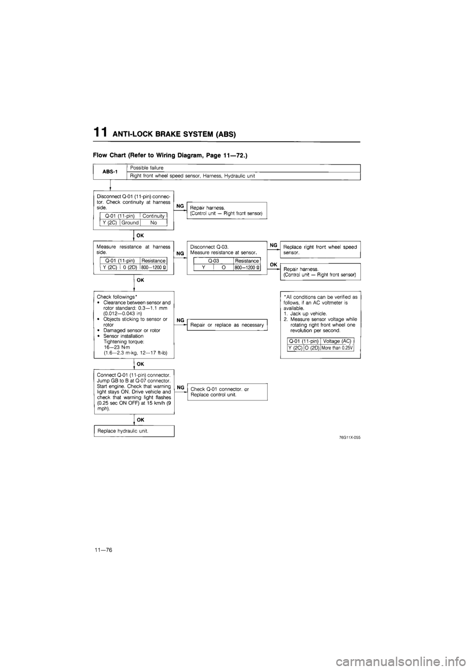
1 1 ANTI-LOCK BRAKE SYSTEM (ABS)
Flow Chart (Refer to Wiring Diagram, Page 11—72.)
ABS-1
Possible failure
Right front wheel speed sensor, Harness, Hydraulic unit
Disconnect Q-01 (11-pin) connec-tor. Check continuity
at
harness side.
Q-01 (11-pin)
I
Continuity
Y (2C) Ground No
OK
Measure resistance
at
harness side.
Q-01 (11-pin) Resistance
Y (2C)
i 0
(2D) 800—1200
Q
OK
NG
Repair harness.
(Control unit — Right front sensor)
NG
Disconnect Q-03. Measure resistance
at
sensor.
Q-03 Resistance
Y
[ O
800—1200 Q
NG
Replace right front wheel speed sensor.
OK
Repair harness.
(Control unit — Right front sensor)
Check followings*
• Clearance between sensor and rotor standard: 0.3—1.1
mm
(0.012-0.043
in)
• Objects sticking
to
sensor
or
rotor
• Damaged sensor
or
rotor
• Sensor installation Tightening torque: 16-23 N-m (1.6-2.3 m-kg, 12—17 ft-lb)
OK
Connect Q-01 (11-pin) connector. Jump GB
to B at
Q-07 connector. Start engine. Check that warning light stays ON. Drive vehicle and check that warning light flashes (0.25 sec ON OFF)
at 15
km/h
(9
mph).
NG
Repair
or
replace
as
necessary
* All conditions can
be
verified
as
follows,
if an AC
voltmeter
is
available. 1. Jack
up
vehicle. 2. Measure sensor voltage while rotating right front wheel
one
revolution
per
second.
Q-01 (11-Din) Voltage (AC)
Y (2C) O (2D) More than 0.25V
NG
Check Q-01 connector,
or
Replace control unit.
OK
Replace hydraulic unit.
76G11X-055
11—76
Page 1469 of 1865
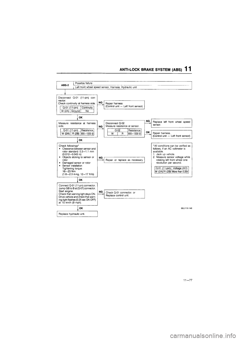
ANTI-LOCK BRAKE SYSTEM (ABS) 1 1
ABS-2
Possible failure
Left front wheel speed sensor, Harness, Hydraulic unit
Disconnect
Q-01
(11-pin)
con-
nector.
Check continuity
at
harness side.
Q-01 (11-pin) Continuity
W (2A) Ground No
OK
Measure side.
Q-01 (11-pin) Resistance
W (2A) R (2B) 800-1200
fl
OK
Connect Q-01 (11-pin) connector. Jump GB
to B
at (Q-07) connector. Start engine.
Check that warning light stays ON. Drive vehicle and check that warn-ing light flashes (0.25 sec ON OFF) at
15
km/h
(9
mph).
NG
Repair harness (Control unit
—
Left front sensor)
resistance
at
harness
NG
Disconnect Q-02 Measure resistance
at
sensor.
Q-02 Resistance
W
| R
800-1200
0
OK
Check followings*
• Clearance between sensor and rotor standard: 0.3—1.1
mm
(0.012-0.043
in)
• Objects sticking
to
sensor
or
rotor • Damaged sensor
or
rotor
• Sensor installation Tightening torque: 16-23 N m
(1.6—2.3 m-kg, 12-17 ft-lb)
NG
OK
NG
Repair
or
replace
as
necessary
NG
Check Q-01 connector,
or
Replace control unit.
OK
Replace hydraulic unit.
Replace left front wheel speed
sensor.
Repair harness.
(Control unit
—
Left front sensor)
"All conditions can
be
verified
as
follows,
if an AC
voltmeter
is
available. 1. Jack
up
vehicle. 2. Measure sensor voltage while rotating left front wheel
one
revolution
per
second.
Q-01 (11-pin) Voltage (AC)
W (2 A)
|
R (2B) More than
0
25V
86U11X-146
11-77