1987 MAZDA 626 air condition
[x] Cancel search: air conditionPage 1784 of 1865
16
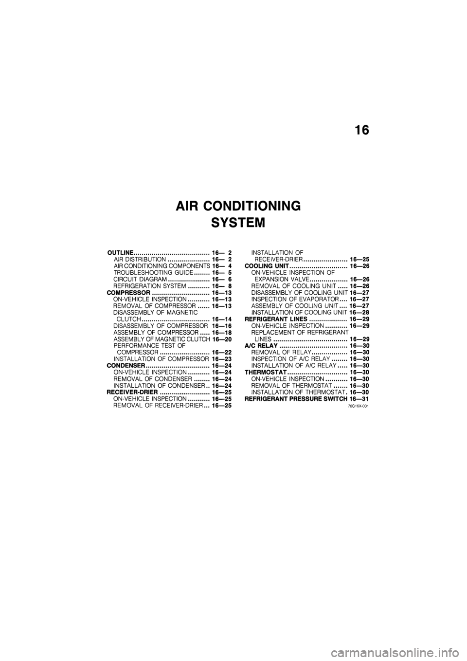
AIR CONDITIONING
SYSTEM
OUTLINE 16— 2
AIR DISTRIBUTION 16— 2
AIR CONDITIONING COMPONENTS 16— 4
TROUBLESHOOTING GUIDE 16— 5
CIRCUIT DIAGRAM 16— 6
REFRIGERATION SYSTEM 16— 8
COMPRESSOR 16—13
ON-VEHICLE INSPECTION 16—13
REMOVAL OF COMPRESSOR 16—13
DISASSEMBLY OF MAGNETIC
CLUTCH 16—14
DISASSEMBLY OF COMPRESSOR 16—16
ASSEMBLY OF COMPRESSOR 16—18
ASSEMBLY OF MAGNETIC CLUTCH 16—20
PERFORMANCE TEST OF
COMPRESSOR 16—22
INSTALLATION OF COMPRESSOR 16—23
CONDENSER 16—24
ON-VEHICLE INSPECTION 16—24
REMOVAL OF CONDENSER 16—24
INSTALLATION OF CONDENSER.. 16—24
RECEIVER-DRIER 16—25
ON-VEHICLE INSPECTION 16—25
REMOVAL OF RECEIVER-DRIER... 16—25
INSTALLATION OF
RECEIVER-DRIER 16—25
COOLING UNIT 16—26
ON-VEHICLE INSPECTION OF
EXPANSION VALVE 16—26
REMOVAL OF COOLING UNIT 16—26
DISASSEMBLY OF COOLING UNIT 16—27
INSPECTION OF EVAPORATOR.... 16—27
ASSEMBLY OF COOLING UNIT.... 16—27
INSTALLATION OF COOLING UNIT 16—28
REFRIGERANT LINES 16—29
ON-VEHICLE INSPECTION 16—29
REPLACEMENT OF REFRIGERANT
LINES 16—29
A/C RELAY 16—30
REMOVAL OF RELAY 16—30
INSPECTION OF A/C RELAY 16—30
INSTALLATION OF A/C RELAY 16—30
THERMOSTAT 16—30
ON-VEHICLE INSPECTION 16—30
REMOVAL OF THERMOSTAT 16-30
INSTALLATION OF THERMOSTAT. 16—30
REFRIGERANT PRESSURE SWITCH 16—31
76G16X-001
Page 1785 of 1865
16 OUTLINE
OUTLINE
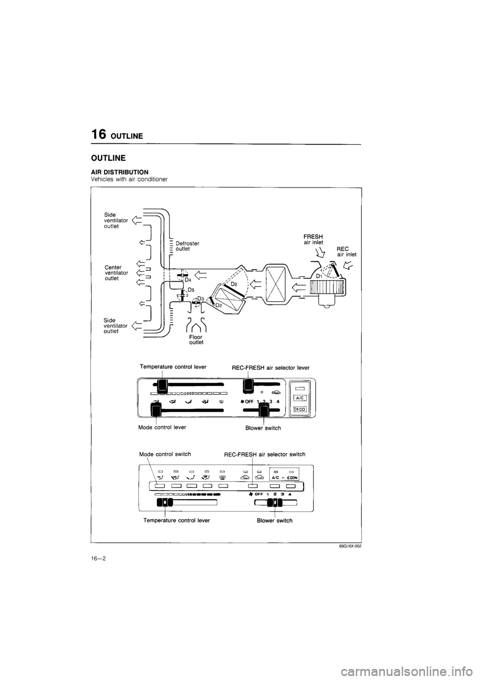
AIR DISTRIBUTION
Vehicles with air conditioner
Side ventilator outlet
1
Center ventilator outlet
- Defroster = outlet
FRESH air inlet
REC air inlet
Side . ventilator < outlet
Floor outlet
Temperature control lever
*
REC-FRESH air selector lever
•QDOODDDaaacziciz) ^^^ ° cQ^
^J 'i, *
OFF
1 7 3 4
Mode control lever
Mode control switch
A/C
DECO
Blower switch
REC-FRESH air selector switch
«?/ ^ W ^
izzi • izn •
C^) A/C - ECDN
• CUD
<=i ac3 a ua • • Jf OFF 12 3 4. SJ
Temperature control lever Blower switch
69G16X002
16-2
Page 1787 of 1865
16 OUTLINE
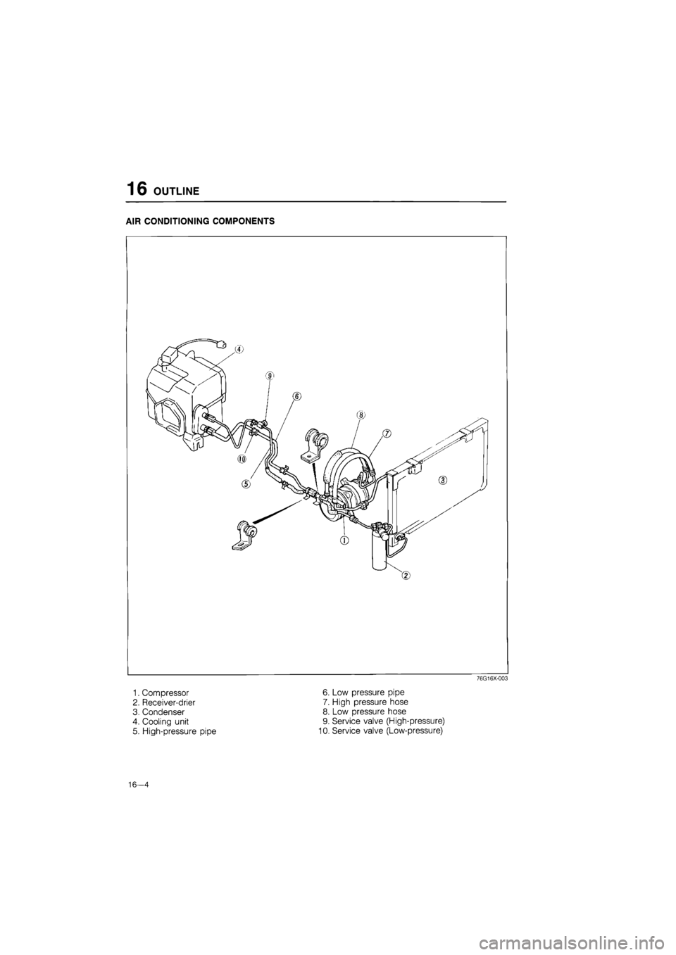
AIR CONDITIONING COMPONENTS
76G16X-003
1. Compressor 6. Low pressure pipe
2. Receiver-drier 7. High pressure hose
3. Condenser 8. Low pressure hose
4. Cooling unit 9. Service valve (High-pressure)
5. High-pressure pipe 10. Service valve (Low-pressure)
16—4
Page 1788 of 1865
OUTLINE 16
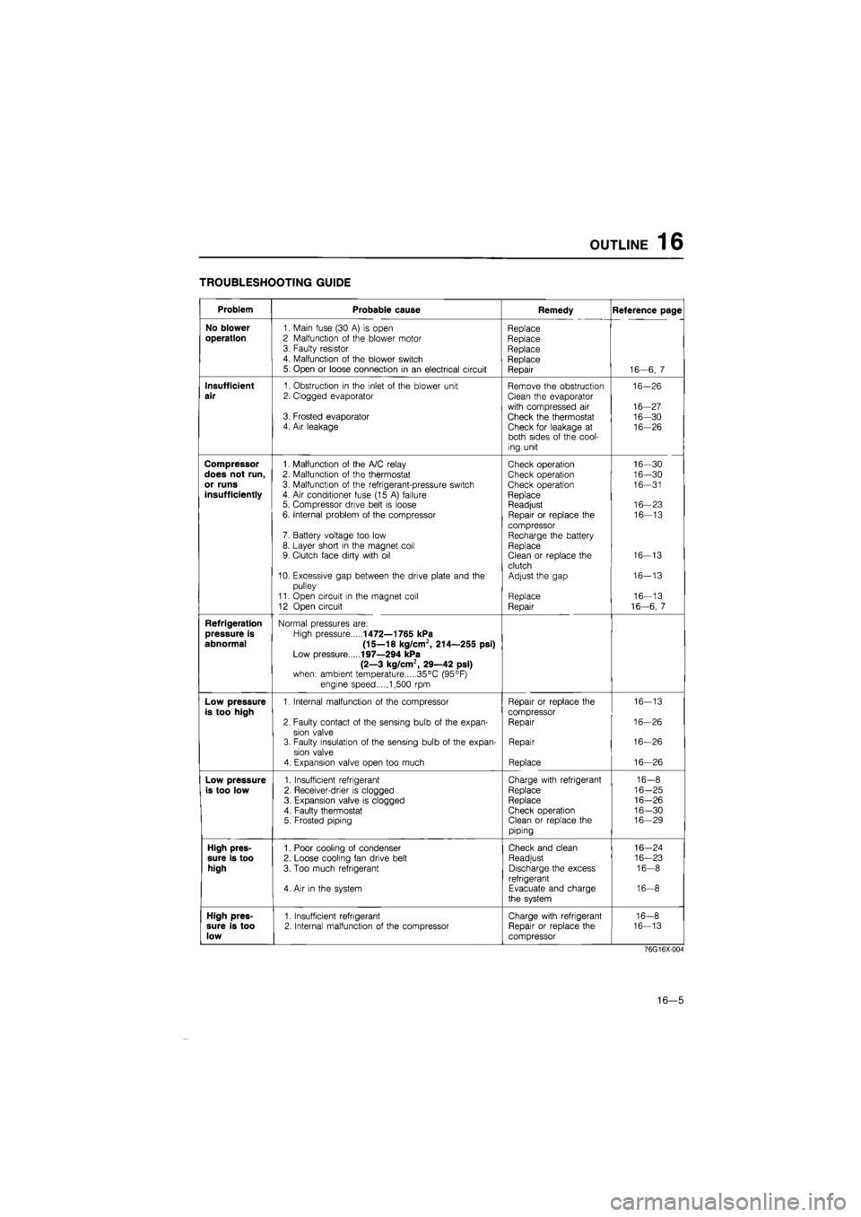
TROUBLESHOOTING GUIDE
Problem Probable cause Remedy Reference page
No blower
1. Main fuse (30
A) is
open Replace
operation
2 Malfunction
of
the blower motor Replace 3. Faulty resistor Replace 4. Malfunction
of
the blower switch Replace 5. Open
or
loose connection
in an
electrical circuit Repair 16—6,
7
Insufficient
1. Obstruction
in
the inlet
of
the blower unit Remove the obstruction 16-26
air
2. Clogged evaporator Clean the evaporator
with compressed
air
16-27 3. Frosted evaporator Check the thermostat 16-30 4. Air leakage Check for leakage
at
16-26 both sides
of
the cool-
ing unit
Compressor
1. Malfunction
of
the A/C relay Check operation 16—30
does not run,
2. Malfunction
of
the thermostat Check operation 16—30
or runs
3. Malfunction
of
the refrigerant-pressure switch Check operation 16—31
insufficiently
4.
Air
conditioner fuse (15
A)
failure Replace 5. Compressor drive belt
is
loose Readjust 16—23
6. Internal problem
of
the compressor Repair
or
replace
the
16—13
compressor 7. Battery voltage too low Recharge the battery 8. Layer short
in
the magnet coil Replace 9. Clutch face dirty with
oil
Clean
or
replace the 16-13
clutch 10. Excessive gap between the drive plate and
the
Adjust the gap 16-13
pulley
11. Open circuit
in
the magnet coil Replace 16—13
12 Open circuit Repair 16-6,
7
Refrigeration
Normal pressures are:
pressure is
High pressure
1472—1765 kPa
abnormal (15—18 kg/cm2, 214—255 psi)
Low pressure
197—294 kPa
(2—3 kg/cm2, 29—42 psi)
when: ambient temperature 35°C (95°F)
engine speed 1,500
rpm
Low pressure
1. Internal malfunction
of
the compressor Repair
or
replace the 16-13
is too high
compressor
2. Faulty contact
of
the sensing bulb
of
the expan-Repair 16-26
sion valve 3. Faulty insulation
of
the sensing bulb
of
the expan-Repair 16—26
sion valve
4. Expansion valve open too much Replace 16—26
Low pressure
1. Insufficient refrigerant Charge with refrigerant 16-8
is too low
2. Receiver-drier
is
clogged Replace 16-25
3. Expansion valve
is
clogged Replace 16-26
4. Faulty thermostat Check operation 16-30 5. Frosted piping Clean
or
replace the 16—29
piping
High pres-
1. Poor cooling
of
condenser Check and clean 16-24
sure is too
2. Loose cooling fan drive belt Readjust 16—23
high
3. Too much refrigerant Discharge the excess 16-8
refrigerant 4.
Air in
the system Evacuate and charge 16-8
the system
High pres-
1. Insufficient refrigerant Charge with refrigerant 16-8
sure is too
2. Internal malfunction
of
the compressor Repair
or
replace the 16-13
low
compressor
76G16X-004
16—5
Page 1791 of 1865
16 OUTLINE
Sight glass
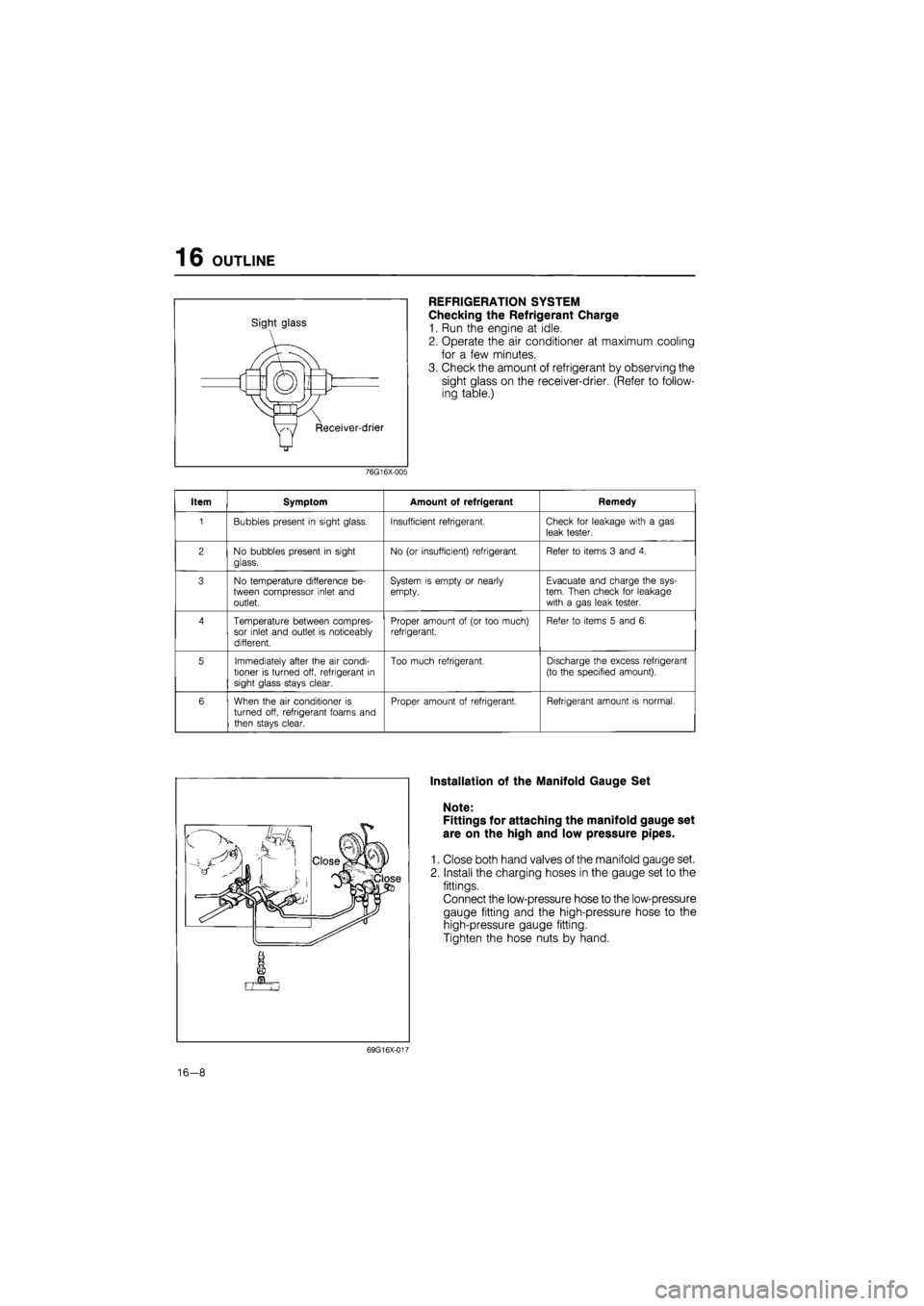
REFRIGERATION SYSTEM
Checking the Refrigerant Charge
1. Run the engine at idle.
2. Operate the air conditioner at maximum cooling
for a few minutes.
3. Check the amount of refrigerant by observing the
sight glass on the receiver-drier. (Refer to follow-
ing table.)
76G16X-005
Item Symptom Amount of refrigerant Remedy
1 Bubbles present
in
sight glass. Insufficient refrigerant. Check
for
leakage with
a gas
leak tester.
2 No bubbles present
in
sight
glass.
No
(or
insufficient) refrigerant. Refer
to
items
3
and
4.
3 No temperature difference
be-
tween compressor inlet and outlet.
System
is
empty
or
nearly empty. Evacuate and charge the sys-tem. Then check
for
leakage with
a
gas leak tester.
4 Temperature between compres-sor inlet and outlet
is
noticeably different.
Proper amount
of (or
too much) refrigerant. Refer
to
items
5
and
6.
5 Immediately after the
air
condi-tioner
is
turned off, refrigerant
in
sight glass stays clear.
Too much refrigerant. Discharge the excess refrigerant
(to the specified amount).
6 When the
air
conditioner
is
turned off, refrigerant foams and
then stays clear.
Proper amount
of
refrigerant. Refrigerant amount
is
normal.
Installation of the Manifold Gauge Set
Note:
Fittings for attaching the manifold gauge set
are on the high and low pressure pipes.
1. Close both hand valves of the manifold gauge set.
2. Install the charging hoses in the gauge set to the
fittings.
Connect the low-pressure hose to the low-pressure
gauge fitting and the high-pressure hose to the
high-pressure gauge fitting.
Tighten the hose nuts by hand.
69G16X-017
16-8
Page 1792 of 1865
OUTLINE 16
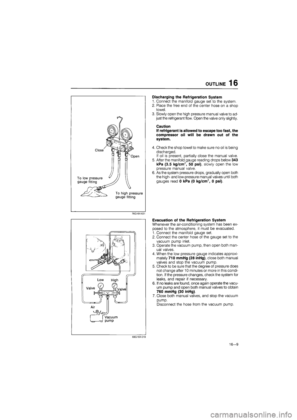
Discharging the Refrigeration System
1. Connect the manifold gauge set to the system.
2. Place the free end of the center hose on a shop
towel.
3. Slowly open the high pressure manual valve to ad-
just the refrigerant flow. Open the valve only slightly.
Caution
If refrigerant is allowed to escape too fast, the
compressor oil will be drawn out of the
system.
4. Check the shop towel to make sure no oil is being
discharged.
If oil is present, partially close the manual valve.
5. After the manifold gauge reading drops below 343
kPa (3.5 kg/cm2, 50 psi), slowly open the low
pressure manual valve.
6. As the system pressure drops, gradually open both
the high- and low-pressure manual valves until both
gauges read 0 kPa (0 kg/cm2, 0 psi).
76G16X-631
Evacuation of the Refrigeration System
Whenever the air-conditioning system has been ex-
posed to the atmosphere, it must be evacuated.
1. Connect the manifold gauge set.
2. Connect the center hose of the gauge set to the
vacuum pump inlet.
3. Operate the vacuum pump, then open both man-
ual valves.
4. When the low pressure gauge indicates approxi-
mately 710 mmHg (28 inHg), close both manual
valves and stop the vacuum pump.
5. Check to be sure that the degree of pressure does
not change after 10 minutes or more in this condi-
tion.
If
the pressure changes, check the system for
leaks, and repair if necessary.
6. If no leaks are found, once again operate the vacu-
um pump and open both manual valves to obtain
760 mmHg (30 inHg).
7. Close both manual valves, and stop the vacuum
pump.
Disconnect the hose from the vacuum pump.
69G16X-019
16-9
Page 1794 of 1865
OUTLINE 16
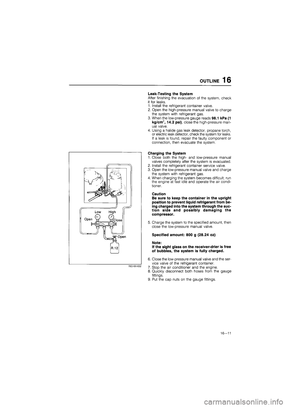
Leak-Testing the System
After finishing the evacuation of the system, check
it for leaks.
1. Install the refrigerant container valve.
2. Open the high-pressure manual valve to charge
the system with refrigerant gas.
3. When the low-pressure gauge reads 98.1 kPa (1
kg/cm2, 14.2 psi), close the high-pressure man-
ual valve.
4. Using a halide gas leak detector, propane torch,
or electric leak detector, check the system for leaks.
If a leak is found, repair the faulty component or
connection, then evacuate the system.
76G16X-632
Charging the System
1. Close both the high- and low-pressure manual
valves completely after the system is evacuated.
2. Install the refrigerant container service valve.
3. Open the low-pressure manual valve and charge
the system with refrigerant gas.
4. When charging the system becomes difficult, run
the engine at fast idle and operate the air condi-
tioner.
Caution
Be sure to keep the container in the upright
position to prevent liquid refrigerant from be-
ing charged into the system through the suc-
tion side and possibly damaging the
compressor.
5. Charge the system to the specified amount, then
close the low-pressure manual valve.
Specified amount: 800 g (28.24 oz)
Note:
If the sight glass on the receiver-drier is free
of bubbles, the system is fully charged.
6. Close the low-pressure manual valve and the ser-
vice valve of the refrigerant container.
7. Stop the air conditioner and the engine.
8. Quickly disconnect both hoses from the gauge
fittings.
9. Put the cap nuts on the gauge fittings.
16—11
Page 1795 of 1865
16 OUTLINE
Thermometer (Dry)
Thermometer
(Dry & Wet)
76G16X-633
69G16X-024
DETERMINING THE RELATIVE HUMI-DITY: Read the temperatures of the dry- and v^et-bulb thermometers at the air inlet (evapo-rator inlet). Then bring them into mutual relation on the chart and determine the intersection, which is the relative humidity^ For exampie, if the dry-bulb temperature^ is 90° F. and the wet-bulb temper- ^ ature is 78° F, the relative humidity is ^ 60%.
DRV BUL8 TEMPERATURE
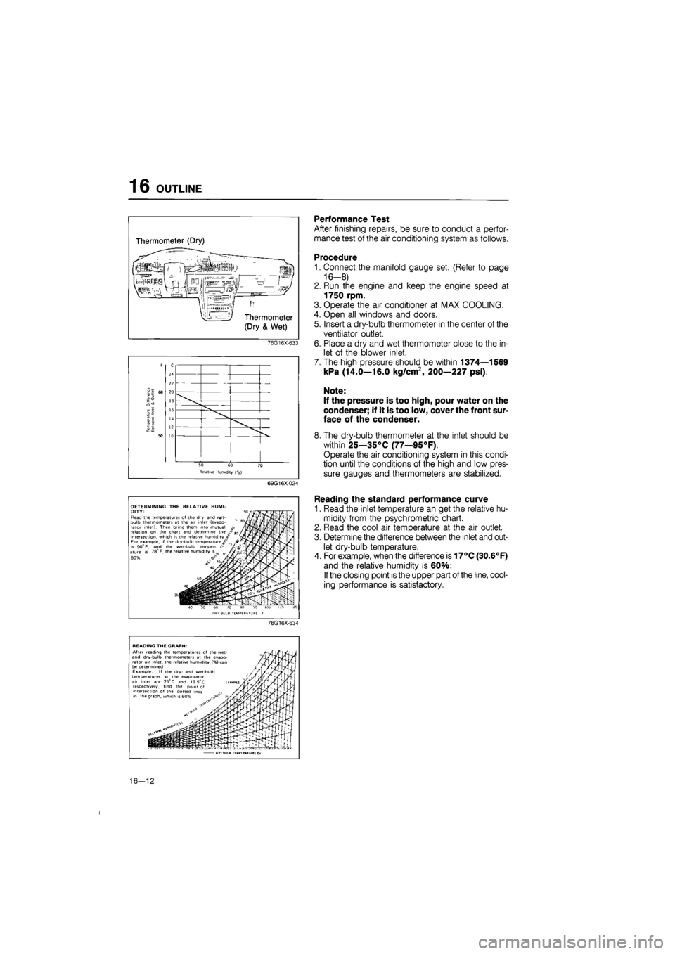
Performance Test
After finishing repairs, be sure to conduct a perfor-
mance test of the air conditioning system as follows.
Procedure
1. Connect the manifold gauge set. (Refer to page
16-8)
2. Run the engine and keep the engine speed at
1750 rpm.
3. Operate the air conditioner at MAX COOLING.
4. Open all windows and doors.
5. Insert a dry-bulb thermometer in the center of the
ventilator outlet.
6. Place a dry and wet thermometer close to the in-
let of the blower inlet.
7. The high pressure should be within 1374—1569
kPa (14.0—16.0 kg/cm2, 200—227 psi).
Note:
If the pressure is too high, pour water on the
condenser; if it is too low, cover the front sur-
face of the condenser.
8. The dry-bulb thermometer at the inlet should be
within 25—35°C (77—95°F).
Operate the air conditioning system in this condi-
tion until the conditions of the high and low pres-
sure gauges and thermometers are stabilized.
Reading the standard performance curve
1. Read the inlet temperature an get the relative hu-
midity from the psychrometric chart.
2. Read the cool air temperature at the air outlet.
3. Determine the difference between the inlet and out-
let dry-bulb temperature.
4. For example, when the difference is 17°C (30.6°F)
and the relative humidity is 60%:
If
the closing point is the upper part of the line, cool-
ing performance is satisfactory.
76G16X-634
READING THE GRAPH: After reading the temperatures of the wet-and dry-bulb thermometers at the evapo-rator air inlet, the relative humidity (%} can be determined Example: If the dry- and wet-bulb temperatures at the evaporator air inlet are 25°
C
and 19 5°C respectively, find the point of intersection of the dotted lines in the graph, which is
• i
•.p-I--!1. fi -GL^TIULB ': "'.L .T.L CL
16—12