Page 1212 of 1865
7C ASSEMBLY
ASSEMBLY-STEP 2
Torque Specifications
29—39 N-m (3.0—4.0 m-kg, 22—29 ft-lb) ©
7C-98
76G07C-251
Page 1213 of 1865
ASSEMBLY 7C
Thrust Washer, Bearing, and Race Locations
Outer diameter of bearing and race
76G07C252
mm (in)
1 2 3 4 5 6 7
Bearing 41.9 (1.65) 52.9 (2.08) 69.9 (2.75) 46.9 (1.85) 69.9 (2.75) 69.9 (2.75) 52.9 (2.08)
Race 41.0 (1.61) 51.5 (2.03) 70.0 (2.76)
—
70.0 (2.76) 70.0 (2.76) 51.5 (2.03)
Note: Install with petroleum jelly to prevent the thrust bearing or bearing race from falling out.
Procedure
1. Install the actuator support.
Tightening torque: 12—16 N-m
(120—160 cm-kg, 104—139 in-lb)
76G07C-253
7C—99
Page 1215 of 1865
ASSEMBLY 7C
(4) Apply ATF to the O-ring, and install it onto the
manual shaft.
(5) Insert the manual shaft and manual plate.
76G07C-258
(6) Install the locknut.
Tightening torque:
29—39 N-m (3.0—4.0 m-kg, 22—29 ft-lb)
(7) Install the bushing into the plate; then install the
plate.
Tightening torque:
5—8 N-m (50—80 cm-kg, 43—69 in-lb)
76G07C-260
4. Install the low and reverse brake piston.
(1) Apply ATF to the inner and outer seals and in-
stall them onto the low and reverse brake
piston.
76G07C-261
7C-101
Page 1220 of 1865
7C ASSEMBLY
ASSEMBLY-STEP 3
Torque Specifications
76G07C-278
7C-106
Page 1221 of 1865
ASSEMBLY 7C
76G07C-279
76G07C-280
76G07C-281
Procedure
1. Install the governor assembly.
(1) Mount the governor along with a new gasket
onto the transaxle case so that the sleeve
projection is aligned with the alignment mark
on the transaxle case.
(2) Install the governor cover along with a new
gasket.
Tightening torque:
8—11 N-m (80—110 cm-kg, 69—95 in-lb)
2. Apply a thin coat of silicone sealant to the contact
surfaces of the converter housing and transaxle
case.
3. Install the transaxle case onto the converter
housing.
Tightening torque:
29—46 N-m (3.0—4.7 m-kg, 22—34 ft-lb)
4. Install the SST into the differential side gear.
Caution
Failure to install the SST may allow the
differential side gears to become misaligned.
76G07C-282
7C-107
Page 1225 of 1865
ASSEMBLY-STEP
4
Torque Specifications
ASSEMBLY
7C
76G07C-295
7C—111
Page 1226 of 1865

7C ASSEMBLY
7C-112
Procedure
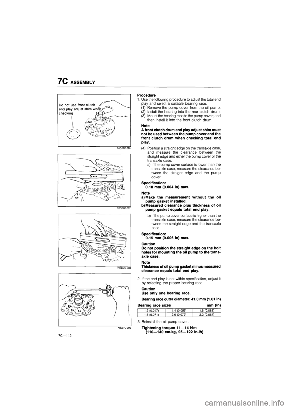
1. Use the following procedure to adjust the total end
play and select a suitable bearing race.
(1) Remove the pump cover from the oil pump.
(2) Install the bearing into the rear clutch drum.
(3) Mount the bearing race to the pump cover; and
then install it into the front clutch drum.
Note
A front clutch drum end play adjust shim must
not be used between the pump cover and the
front clutch drum when checking total end
play.
(4) Position a straight edge on the transaxle case,
and measure the clearance between the
straight edge and either the pump cover or the
transaxle case.
a) If the pump cover surface is lower than the
transaxle case, measure the clearance be-
tween the straight edge and the pump
cover.
Specification:
0.10 mm (0.004 in) max.
Note
a) Make the measurement without the oil
pump gasket installed.
b) Measured clearance plus thickness of oil
pump gasket equals total end play.
b) If the pump cover surface is higher than the
transaxle case, measure the clearance be-
tween the straight edge and the transaxle
case.
Specification:
0.15 mm (0.006 in) max.
Caution
Do not position the straight edge on the bolt
holes for mounting the oil pump to the trans-
axle case.
Note
Thickness of oil pump gasket minus measured
clearance equals total end play.
2. If the end play is not within specification, adjust it
by selecting the proper bearing race.
Caution
Use only one bearing race.
Bearing race outer diameter: 41.0 mm (1.61 in)
Bearing race sizes mm (in)
1.2 (0.047) 1.4 CO.055) 1.6 (0.063)
1.8 (0.071) 2.0 (0.079) 2.2 (0.087)
3. Reinstall the oil pump cover.
Tightening torque: 11—14 N-m
(110—140 cm-kg, 95—122 in-lb)
Page 1227 of 1865

ASSEMBLY 7C
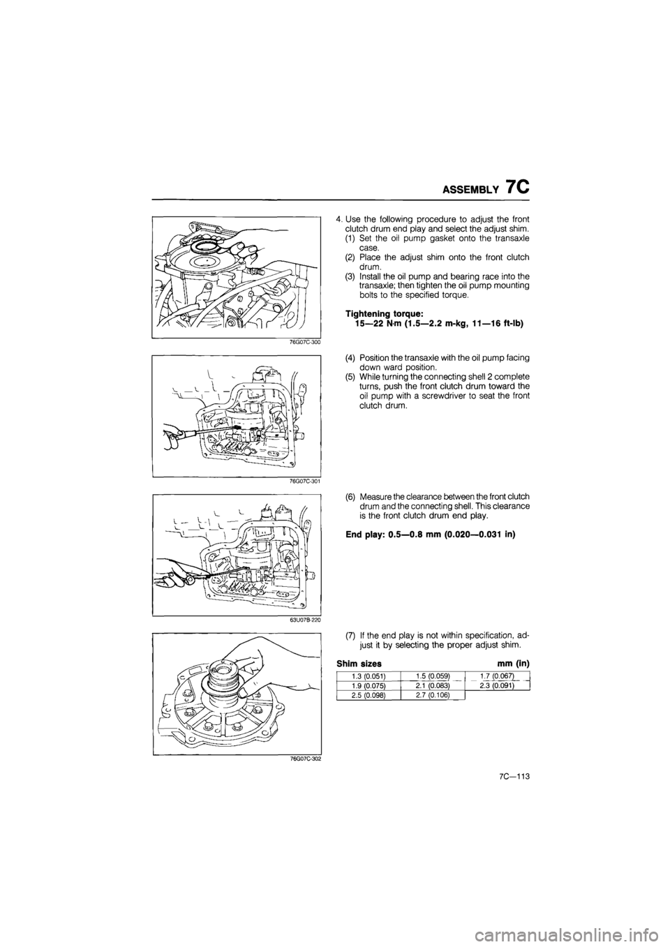
4. Use the following procedure to adjust the front
clutch drum end play and select the adjust shim.
(1) Set the oil pump gasket onto the transaxle
case.
(2) Place the adjust shim onto the front clutch
drum.
(3) Install the oil pump and bearing race into the
transaxle; then tighten the oil pump mounting
bolts to the specified torque.
Tightening torque:
15—22 N m (1.5—2.2 m-kg, 11—16 ft-lb)
76G07C-300
76G07C-301
63U07B-220
(4) Position the transaxle with the oil pump facing
down ward position.
(5) While turning the connecting shell 2 complete
turns, push the front clutch drum toward the
oil pump with a screwdriver to seat the front
clutch drum.
(6) Measure the clearance between the front clutch
drum and the connecting shell. This clearance
is the front clutch drum end play.
End play: 0.5—0.8 mm (0.020—0.031 in)
(7) If the end play is not within specification, ad-
just it by selecting the proper adjust shim.
Shim sizes mm (in)
1.3 (0.051) 1.5 (0.059) 1.7 (0.067)
2.3 (0.091) 1.9 (0.075) 2.1 (0.083)
1.7 (0.067)
2.3 (0.091)
2.5 (0.098) 2.7 (0.106)
76G07C-302
7C-113