Page 1264 of 1865
FRONT AXLE 9
86U09X-023
86U09X-024
86U09X-025
4. Install the stabilizer.
Dimension: 20.1 mm (0.79 in)
Tightening torque: 16—23 N-m
(1.6—2.3 m-kg, 12—17 ft-lb)
5. Install the wheel speed sensor. (ABS)
Tightening torque: 16—23 N-m
(1.6—2.3 m-kg, 12—17 ft-lb)
6. Install the tie-rod end.
Tightening torque: 29—44 N-m
(3.0—4.5 m-kg, 22—33 ft-lb)
86U09X-026
7. Check the end play. (Refer to page 9—8)
End play: 0.2 mm (0.0079 in) max.
8. Stake the lock nut to groove.
9. Install the caliper assembly.
Tightening torque: 78—98 N-m
(8.0—10.0 m-kg, 58—72 ft-lb)
10. Install the wheel.
Tightening torque: 88—118 N-m
(9.0—12.0 m-kg, 65—87 ft-lb)
9-15
Page 1265 of 1865
9 REAR AXLE
86U09X-027
69G09X-012
76G09X-003
REAR AXLE
ON-VEHICLE MAINTENANCE
Wheel Bearing Play
1.Jack up the vehicle and support it with safety
stands.
2. Check that there is no abnormal noise and that the
tire rotates smoothly when rotated by hand.
3. Remove the wheel.
4. Remove the caliper assembly and suspend it us-
ing a rope.
5. Position a dial indicator against the hub cap, then
push and pull the front wheel hub or brake drum
by hand in the axial direction and measure the end
play of the wheel bearing.
If the end play exceeds specification, replace the
wheel bearing.
End play: 0.2 mm (0.0079 in) max.
6. Install the caliper assembly. (Disc)
Tightening torque: 45—67 N-m
(4.6—6.8 m-kg, 33—49 ft-lb)
7. Install the wheel.
Tightening torque: 88—118 N-m
(9.0—12.0 m-kg, 65—87 ft-lb)
86U09X-029
9—16
Page 1269 of 1865
9 REAR AXLE
INSTALLATION
Install in the reverse order of removal referring to the installation note.
Torque specifications
93—117 N m (9.5—11.9 m-kg, 69—86 ft-lb)
13—22 N-m (1.3—2.2 m-kg, 9—16 ft-lb)
86—117 N-m (8.8—11.9 m-kg, 64—86 ft-lb)
45—59 N-m (4.6-6.0 m-kg, 33—44 ft-lb)
98—177 N-m (10—18m-kg, 73—131 ft-lb)
86U09X-037
installation Note
Brake pipe
1. Connect the brake pipe with the SST.
Tightening torque: 13—22 N-m
(1.3—2.2 m-kg, 9—16 ft-lb)
2. Bleed the air. (Refer to Section 11)
End play
Measure the end play. (Refer to page 9—16)
86U09X-038
9—20
Page 1275 of 1865
9 REAR AXLE
INSTALLATION (2WS)
Install in the reverse order of removal.
Torque Specifications
11—25 N m (1.1—2.6 m-kg, B—19 ft-lb)
45—67 N m {4.6—6.8 m-kg, / 33—49 ft-lb)
16-23 N m ^ (1.6—2.3 m-kg, 12-17 ft-lb)
86—117 N-m (8.8—11.9 m-kg, 64—86 ft-lb)
20—28 N-m (2.0—2.9 m-kg, 14—21 ft-lb)
16—23 N-m (1.6—2.3 m-kg, 12—17 ft-lb)
98—117 N-m (10—18 m-kg, 73—131 ft-lb)
86U09X-049
Installation Note
End play
Measure the end play. (Refer to page 9—16)
End play: 0.2 mm (0.0079 in) max.
86U09X-050
9-26
Page 1276 of 1865
REAR AXLE 9
INSTALLATION (4WS)
Install in the reverse order of removal.
Torque Specifications
©
86U09X-052
86U09X-051
Installation Note
End play
Measure the end play. (Refer to page 9—16)
End play: 0.2 mm (0.0079 in) max.
9—27
Page 1286 of 1865
DRIVESHAFT 9
INSTALLATION
Install in the reverse order of removal referring to the installation note.
Torque specifications
42—62 N m (4.3—6.3 m-kg, 31—46 ft-lb)
8—11 N-m (80—110 cm-kg,
7—10 N-m (70—100 cm-kg, 60—86 in-lb)
16—23 N-m
(1.6—2.3 m-kg, 12—17 ft-lb)
29—44 N-m (3.0—4.5 m-kg, 22—33 ft-lb)
43—54 N-m (4.4—5.5 m-kg, 32—40 ft-lb)
8—11 N-m (80—110 cm-kg, 69—95 In-lb)
235—319 N-m (24.0—32.5 m-kg, 174—235 ft-lb)
88—118 N-m (9.0—12.0 m-kg 65—87 ft-lb)
86U09X-070
I Apply grease
^^TBT0J
if
Clip
Installation Note
Clip
Install a new clip.
Note
a) Before installing the shaft, check the trans-
axle oil seal for damage.
b) Apply transaxle oil to the oil seal lip.
86U09X-071
9-37
Page 1287 of 1865
9 DRIVESHAFT
Front wheel hub
After installation, pull the front wheel hub outward and
check that the driveshaft does not come out.
86U09X-072
Stabilizer
Lock the nut with 20.1 mm (0.79 in) of the threads
exposed.
Tightening torque: 16—23 N-m
(1.6—2.3 m-kg, 12—17 ft-lb)
76G09X-004
9—38
Page 1298 of 1865

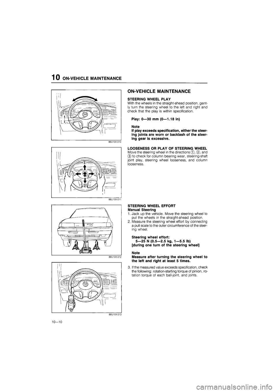
1 0 ON-VEHICLE MAINTENANCE
86U10X-010
ON-VEHICLE MAINTENANCE
STEERING WHEEL PLAY
With the wheels in the straight-ahead position, gent-
ly turn the steering wheel to the left and right and
check that the play is within specification.
Play: 0—30 mm (0—1.18 in)
Note
If play exceeds specification, either the steer-
ing joints are worn or backlash of the steer-
ing gear is excessive.
LOOSENESS OR PLAY OF STEERING WHEEL
Move the steering wheel in the directions ©, ©, and
© to check for column bearing wear, steering-shaft
joint play, steering wheel looseness, and column
looseness.
86U10X-011
86U10X-012
STEERING WHEEL EFFORT
Manual Steering
1. Jack up the vehicle. Move the steering wheel to
put the wheels in the straight-ahead position.
2. Measure the steering wheel effort by connecting
a pull scale to the outer circumference of the steer-
ing wheel.
Steering wheel effort:
5—25 N (0.5—2.5 kg, 1—5.5 lb)
[during one turn of the steering wheel]
Note
Measure after turning the steering wheel to
the left and right at least 5 times.
3. If the measured value exceeds specification, check
the following: rotation-starting torque of pinion, ro-
tation torque of each ball-joint, and joints.
86U10X-013
10—10