Page 1402 of 1865

1 1 BRAKE HYDRAULIC LINE
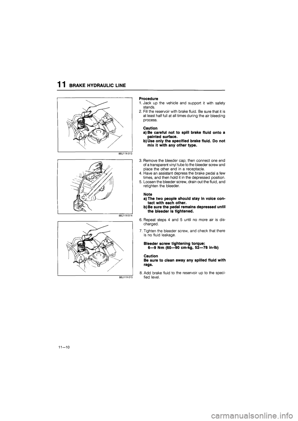
Procedure
1. Jack up the vehicle and support it with safety
stands.
2. Fill the reservoir with brake fluid. Be sure that it is
at least half full at all times during the air bleeding
process.
Caution
a) Be careful not to spill brake fluid onto a
painted surface.
b)Use only the specified brake fluid. Do not
mix it with any other type.
3. Remove the bleeder cap; then connect one end
of a transparent vinyl tube to the bleeder screw and
place the other end in a receptacle.
4. Have an assistant depress the brake pedal a few
times, and then hold it in the depressed position.
5. Loosen the bleeder screw, drain out the fluid, and
retighten the bleeder.
Note
a) The two people should stay in voice con-
tact with each other.
b) Be sure the pedal remains depressed until
the bleeder is tightened.
86U11X-014
6. Repeat steps 4 and 5 until no more air is dis-
charged.
7. Tighten the bleeder screw, and check that there
is no fluid leakage.
Bleeder screw tightening torque:
6—9 N-m (60—90 cm-kg, 52—78 in-lb)
Caution
Be sure to clean away any spilled fluid with
rags.
8. Add brake fluid to the reservoir up to the speci-
fied level.
11—10
Page 1403 of 1865

BRAKE PEDAL 1 1
Pedal height
"tt^
Pedal-to-floor clearance
76G11X-008
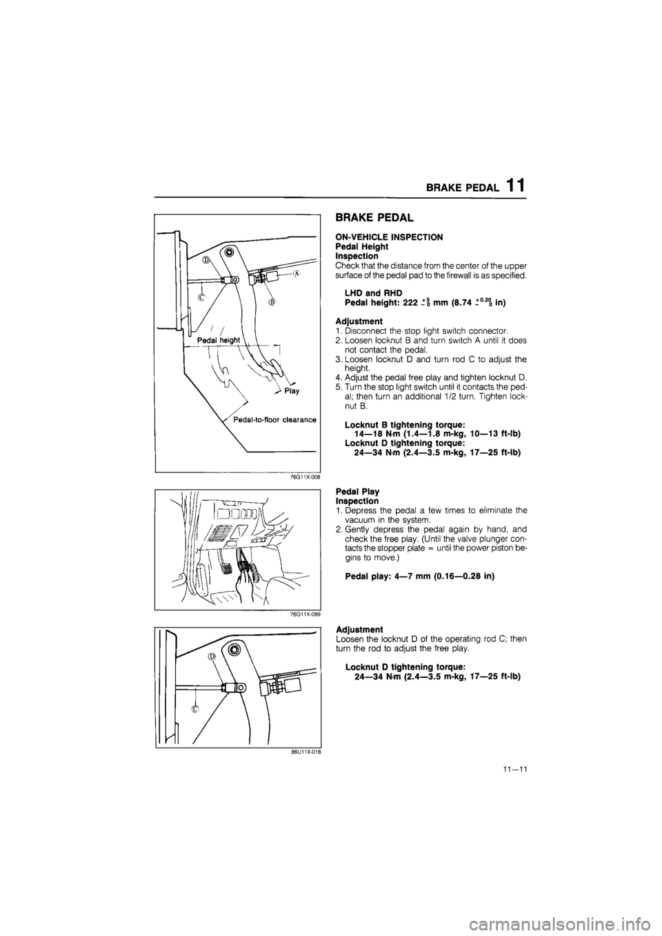
BRAKE PEDAL
ON-VEHICLE INSPECTION
Pedal Height
Inspection
Check that the distance from the center of the upper
surface of the pedal pad to the firewall is as specified.
LHD and RHD
Pedal height: 222 mm (8.74 +0-200 in)
Adjustment
1. Disconnect the stop light switch connector.
2. Loosen locknut B and turn switch A until it does
not contact the pedal.
3. Loosen locknut D and turn rod C to adjust the
height.
4. Adjust the pedal free play and tighten locknut D.
5. Turn the stop light switch until it contacts the ped-
al; then turn an additional 1/2 turn. Tighten lock-
nut B.
Locknut B tightening torque:
14—18 N m (1.4—1.8 m-kg, 10—13 ft-lb)
Locknut D tightening torque:
24—34 Nm (2.4—3.5 m-kg, 17—25 ft-lb)
Pedal Play
Inspection
1. Depress the pedal a few times to eliminate the
vacuum in the system.
2. Gently depress the pedal again by hand, and
check the free play. (Until the valve plunger con-
tacts the stopper plate = until the power piston be-
gins to move.)
Pedal play: 4—7 mm (0.16—0.28 in)
76G11X-099
Adjustment
Loosen the locknut D of the operating rod C; then
turn the rod to adjust the free play.
Locknut D tightening torque:
24—34 Nm (2.4—3.5 m-kg, 17—25 ft-lb)
86U11X-018
11—11
Page 1405 of 1865
BRAKE PEDAL 1 1
INSPECTION
Check the following and replace or repair any faulty
parts.
1. Pedal pad for wear or damage
2. Bushing for wear
3. Bolt for bending
4. Pedal for bending
5. Return spring for weakness or damage
86U11X-021
INSTALLATION
1. Install in the reverse order of removal.
2. Tighten all nuts and bolts, referring to torque specifications.
3. After installation:
Check and adjust the pedal height and play. (Refer to page 11—11.)
Torque specifications
76G11X-010
Installation Note
Application of grease
Apply grease to the following parts:
(1) Inner and outer surfaces of bushing
(2) Outer surface of guide pipe
(3) Contact surface of clevis pin and spring
86U11X-023
11—13
Page 1414 of 1865
1 1 MASTER CYLINDER
INSTALLATION
1. Install in the reverse order of removal.
2. Tighten all nuts and bolts to the specified torque, referring to torque specifications.
3. After installation:
(1) Fill the reservoir with the specified fluid.
(2) Bleed air from the system. (Refer to page 11—9.)
(3) Check each part for fluid leakage.
Torque specifications
11—22
Page 1416 of 1865

1 1 MASTER CYLINDER
76G11X-025
II
L
\ Clearance (B)
Clearance (A) , j Adjust nut
•I
76G11X-026
Clearance (B)
49 B043 001
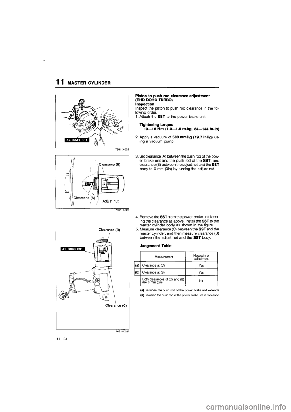
Piston to push rod clearance adjustment
(RHD DOHC TURBO)
Inspection
Inspect the piston to push rod clearance in the fol-
lowing order.
1. Attach the SST to the power brake unit.
Tightening torque:
10—16 N-m (1.0—1.6 m-kg, 84—144 in-lb)
2. Apply a vacuum of 500 mmHg (19.7 inHg) us-
ing a vacuum pump.
3. Set clearance (A) between the push rod of the pow-
er brake unit and the push rod of the SST, and
clearance (B) between the adjust nut and the SST
body to 0 mm (Oin) by turning the adjust nut.
4. Remove the SST from the power brake unit keep-
ing the clearance as above. Install the SST to the
master cylinder body as shown in the figure.
5. Measure clearance (C) between the SST and the
master cylinder, and then measure clearance (B)
between the adjust nut and the SST body.
Judgement Table
Measurement Necessity of adjustment
(a) Clearance at (C) Yes
(b) Clearance at (B) Yes
Both clearances of (C) and (B) are 0 mm (Oin) No
(a) is when the push rod of the power brake unit extends.
(b) is when the push rod of the power brake unit is recessed.
76G11X-027
11-24
Page 1425 of 1865
POWER BRAKE UNIT 1 1
INSTALLATION
1. Install in the reverse order of removal, referring to installation note for specially marked parts.
2. Tighten all nuts and bolts to the specified torque, referring to torque specifications.
3. After installation:
(1) Add fluid and bleed the air. (Refer to page 11—9.)
(2) Check all parts for fluid leakage.
(3) Make an on-vehicle check of the unit (Refer to page 11—27.)
(4) Verify that the vacuum hose does not contact other parts.
Torque specifications
76G11X-035
1. Vacuum hose and check valve
11—33
Page 1428 of 1865

1 1 VACUUM PUMP
Vacuum pump
Checking
point
B -
VacuumA^^^^ pump [
(o) y
©
Rear
\ camshaft
jpulley
AHP"
76G11X-039
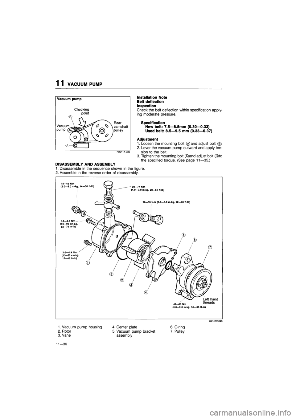
DISASSEMBLY AND ASSEMBLY
1. Disassemble in the sequence shown in the figure.
2. Assemble in the reverse order of disassembly.
Installation Note
Belt deflection
Inspection
Check the belt deflection within specification apply-
ing moderate pressure.
Specification
New belt: 7.5—8.5mm (0.30—0.33)
Used belt: 8.5—9.5 mm (0.33—0.37)
Adjustment
1. Loosen the mounting bolt ©and adjust bolt (§).
2. Lever the vacuum pump outward and apply ten-
sion to the belt.
3. Tighten the mounting bolt ®and adjust bolt (§)to
the specified torque. (See page 11 —35.)
18—49 N-m (2.0—5.0 m-kg, 14—36 ft-lb) ' 39—77 N-m (4.0—7.0 m-kg, 29—51 ft-lb)
29—59 N-m (3.0—6.0 m-kg, 22—43 ft-lb)
,_B.B Nm--90 cm-kg, 5.9 (60 52—78 In-lb)
2.0—4.9 N-m (20—50 cm-kg, 17—43 In-lb)
49—88 Nm (5.0-9.0 m-kg, 51—65 It-lb)
Left hand threads
1. Vacuum pump housing
2. Rotor
3. Vane
76G11X-040
4. Center plate
5. Vacuum pump bracket
assembly
6. O-ring
7. Pulley
11-36
Page 1430 of 1865
![MAZDA 626 1987 Workshop Manual
1
1
DUAL PROPORTIONING VALVE
B6U11X-060
DUAL PROPORTIONING VALVE
FUNCTION CHECK
1. Connect
two
pressure gauges [9,810
kPa (100
kg/cm2,1,422 psi)
]
to the brake pipes and adap-
tors
as
MAZDA 626 1987 Workshop Manual
1
1
DUAL PROPORTIONING VALVE
B6U11X-060
DUAL PROPORTIONING VALVE
FUNCTION CHECK
1. Connect
two
pressure gauges [9,810
kPa (100
kg/cm2,1,422 psi)
]
to the brake pipes and adap-
tors
as](/manual-img/28/57059/w960_57059-1429.png)
1
1
DUAL PROPORTIONING VALVE
B6U11X-060
DUAL PROPORTIONING VALVE
FUNCTION CHECK
1. Connect
two
pressure gauges [9,810
kPa (100
kg/cm2,1,422 psi)
]
to the brake pipes and adap-
tors
as
shown
in
the
figure.
Adaptor and flare
nut
tightening torque:
13—22 N m (1.3—2.2 m-kg, 9—16 ft-lb)
Note
Disconnect and connect the brake pipes with
the
SST
(49
0259 770B).
2. Bleed
air
from
the
brake system.
(Refer
to
page 11—9.)
76G11X-043
t 0}
^
£
»
Rear
brake
pressu
kPa
(kg/cm2,
p
>
DO
Rear
brake
pressu
kPa
(kg/cm2,
p
>
DO
TTi
A
B
Master cylinder pressure
kPa
(kg/cm2,
psi)
76G11X-044
Depress the brake pedal until the master cylinder
pressure equals A; then measure rear brake pres-
sure
A'.
Depress the brake pedal again; apply additional
pressure until
A
equals
B;
then measure pressure
B'.
If the measurements
are
not
within specification,
replace
the
valve assembly.
Install the brake pipes to the valve,
and
bleed
air
from
the
brake system.
Specification
Fluid pressure
kPa
(kg/cm2,
psi)
A A' B B'
Except General
LHD
and
RHD
1,962 (20,284)
1,962 ±
196
(20
± 2,
284
± 28)
6,867 (70,995)
3,434 ±
196
(35
± 2,
498
± 28)
General
LHD
and
RHD
2,943 (30,427)
2,943 ±
196
(30
± 2,
427
± 28)
6,867 (70,995) 4,120 ±
196
(42
± 2,
597
± 28)
11-38