Page 1462 of 1865
1 1 PARKING BRAKE
Rear disc brake
(70—100 cm-kg, 61—87 In-lb)
86U11X-138
1. Parking brake cable (rear disc brake)
Installation Note
Parking brake cable (Rear disc brake)
Connect the cable end to the operating lever; then
tighten the locknut.
Tightening torque:
20—28 N m (2.0—2.9 m-kg, 14—21 ft-lb)
Caution
There must be no clearance between the ca-
ble end and the operating lever.
86U11X-139
11-70
Page 1468 of 1865

1 1 ANTI-LOCK BRAKE SYSTEM (ABS)
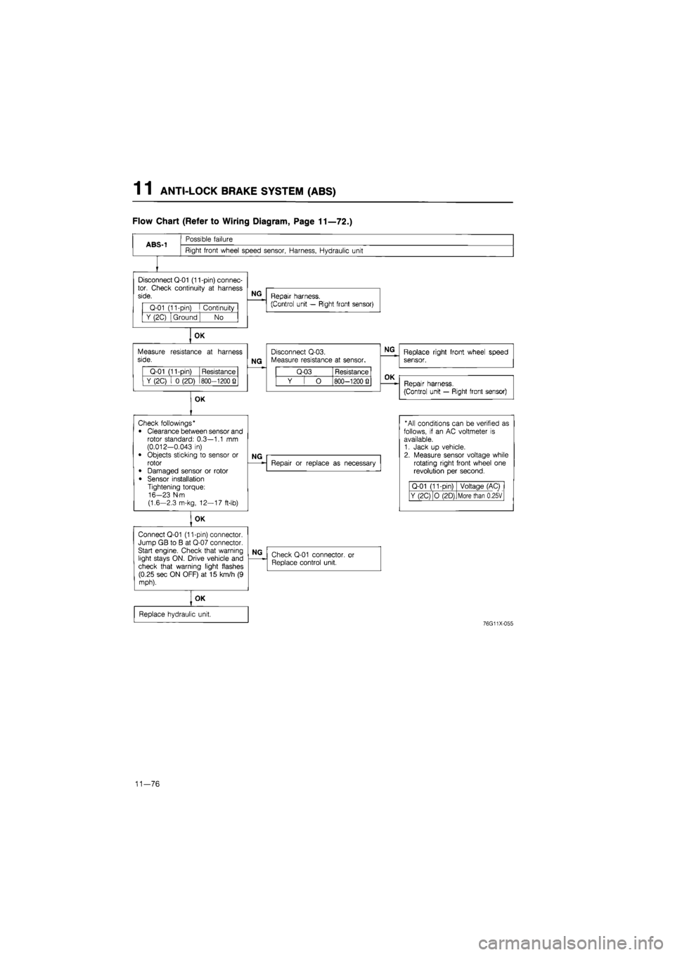
Flow Chart (Refer to Wiring Diagram, Page 11—72.)
ABS-1
Possible failure
Right front wheel speed sensor, Harness, Hydraulic unit
Disconnect Q-01 (11-pin) connec-tor. Check continuity
at
harness side.
Q-01 (11-pin)
I
Continuity
Y (2C) Ground No
OK
Measure resistance
at
harness side.
Q-01 (11-pin) Resistance
Y (2C)
i 0
(2D) 800—1200
Q
OK
NG
Repair harness.
(Control unit — Right front sensor)
NG
Disconnect Q-03. Measure resistance
at
sensor.
Q-03 Resistance
Y
[ O
800—1200 Q
NG
Replace right front wheel speed sensor.
OK
Repair harness.
(Control unit — Right front sensor)
Check followings*
• Clearance between sensor and rotor standard: 0.3—1.1
mm
(0.012-0.043
in)
• Objects sticking
to
sensor
or
rotor
• Damaged sensor
or
rotor
• Sensor installation Tightening torque: 16-23 N-m (1.6-2.3 m-kg, 12—17 ft-lb)
OK
Connect Q-01 (11-pin) connector. Jump GB
to B at
Q-07 connector. Start engine. Check that warning light stays ON. Drive vehicle and check that warning light flashes (0.25 sec ON OFF)
at 15
km/h
(9
mph).
NG
Repair
or
replace
as
necessary
* All conditions can
be
verified
as
follows,
if an AC
voltmeter
is
available. 1. Jack
up
vehicle. 2. Measure sensor voltage while rotating right front wheel
one
revolution
per
second.
Q-01 (11-Din) Voltage (AC)
Y (2C) O (2D) More than 0.25V
NG
Check Q-01 connector,
or
Replace control unit.
OK
Replace hydraulic unit.
76G11X-055
11—76
Page 1469 of 1865

ANTI-LOCK BRAKE SYSTEM (ABS) 1 1
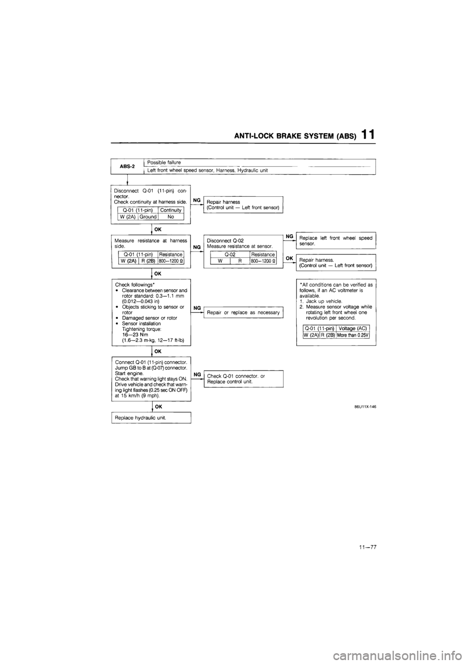
ABS-2
Possible failure
Left front wheel speed sensor, Harness, Hydraulic unit
Disconnect
Q-01
(11-pin)
con-
nector.
Check continuity
at
harness side.
Q-01 (11-pin) Continuity
W (2A) Ground No
OK
Measure side.
Q-01 (11-pin) Resistance
W (2A) R (2B) 800-1200
fl
OK
Connect Q-01 (11-pin) connector. Jump GB
to B
at (Q-07) connector. Start engine.
Check that warning light stays ON. Drive vehicle and check that warn-ing light flashes (0.25 sec ON OFF) at
15
km/h
(9
mph).
NG
Repair harness (Control unit
—
Left front sensor)
resistance
at
harness
NG
Disconnect Q-02 Measure resistance
at
sensor.
Q-02 Resistance
W
| R
800-1200
0
OK
Check followings*
• Clearance between sensor and rotor standard: 0.3—1.1
mm
(0.012-0.043
in)
• Objects sticking
to
sensor
or
rotor • Damaged sensor
or
rotor
• Sensor installation Tightening torque: 16-23 N m
(1.6—2.3 m-kg, 12-17 ft-lb)
NG
OK
NG
Repair
or
replace
as
necessary
NG
Check Q-01 connector,
or
Replace control unit.
OK
Replace hydraulic unit.
Replace left front wheel speed
sensor.
Repair harness.
(Control unit
—
Left front sensor)
"All conditions can
be
verified
as
follows,
if an AC
voltmeter
is
available. 1. Jack
up
vehicle. 2. Measure sensor voltage while rotating left front wheel
one
revolution
per
second.
Q-01 (11-pin) Voltage (AC)
W (2 A)
|
R (2B) More than
0
25V
86U11X-146
11-77
Page 1470 of 1865

1 1 ANTI-LOCK BRAKE SYSTEM (ABS)
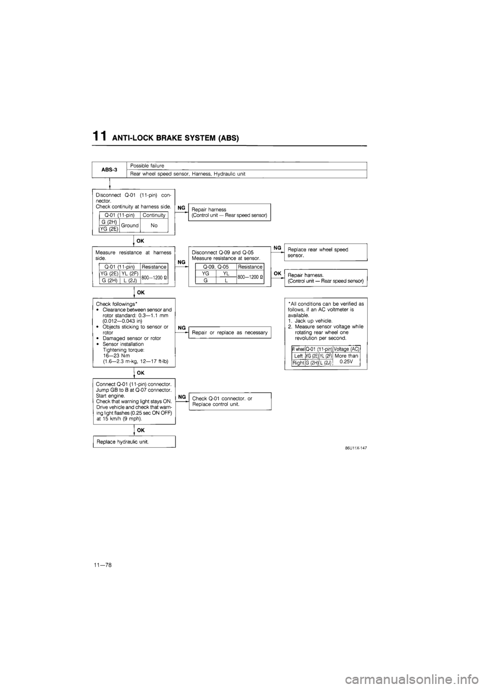
ABS-3
Possible failure
Rear wheel speed sensor, Harness, Hydraulic unit
Disconnect
Q-01
(11-pin)
con-
nector.
Check continuity
at
harness side.
Q-01 (11-pin) Continuity
G (2H) Ground No YG (2E) Ground No
Measure side.
Q-01 (11-pin) Resistance
YG (2E) YL (2F) 800—1200
fi
G (2H)
] L
(2J) 800—1200
fi
OK
Connect Q-01 (11-pin) connector. Jump GB
to B at
Q-07 connector. Start engine.
Check that warning light stays ON. Drive vehicle and check that warn-ing light flashes (0.25 sec ON OFF) at
15
km/h
(9
mph).
NG
Repair harness (Control unit
—
Rear speed sensor)
OK
resistance
at
harness
NG
Disconnect Q-09 and Q-05 Measure resistance
at
sensor.
Q-09, Q-05 Resistance
YG YL 800-1200
0
G L 800-1200
0
OK
Check followings* • Clearance between sensor and rotor standard: 0.3—1.1
mm
(0.012-0.043
in)
• Objects sticking
to
sensor
or
rotor
• Damaged sensor
or
rotor
• Sensor installation Tightening torque: 16-23 N-m
(1.6—2.3 m-kg, 12—17 ft-lb)
NG
Repair
or
replace
as
necessary
NG
Check Q-01 connector. Replace control unit.
or
OK
Replace hydraulic unit,
Replace rear wheel speed
sensor.
OK
Repair harness.
(Control unit
—
Rear speed sensor)
* All conditions can
be
verified
as
follows,
if an AC
voltmeter
is
available. 1. Jack
up
vehicle. 2. Measure sensor voltage while rotating rear wheel
one
revolution
per
second.
fi
wheel Q-01 (11-pin) Voltaqe (AC)
Left |YG (2E) YL (2F) More than 0.25V Right G (2H) L(2J)
More than 0.25V
86U11X-147
11-78
Page 1480 of 1865
1 1 ANTI-LOCK BRAKE SYSTEM (ABS)
86U11X-170
86U11X-171
Removal of Front Wheel Speed Sensor
1. Remove the wheel and tire.
2. Remove the parts shown in the figure, and remove
the sensor from the knuckle.
Installation of Front Wheel Speed Sensor
1. Install the sensor to the knuckle.
Tightening torque:
16—23 N m (1.6—2.3 m-kg, 12—17 ft-lb)
Caution
The left and right sensors are not interchange-
able. L or R is indicated on the bracket.
2. Install the sensor harness bracket onto the knuckle.
Tightening torque:
16—23 Nm (1.6—2.3 m-kg, 12—17 ft-lb)
3. Push the sensor harness through the splash shield
and secure it with the clip.
4. Install the sensor harness bracket to the body.
Tightening torque:
16—23 Nm (1.6—2.3 m-kg, 12—17 ft-lb)
Caution
Verify that the harness is not twisted and does
not contact the shock absorber or body when
the steering wheel is turned.
5. Connect the sensor connector.
6. Install the wheel and tire.
86U11X-172
11-88
Page 1481 of 1865

ANTI-LOCK BRAKE SYSTEM (ABS) 1 1
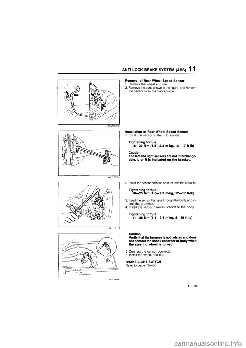
Removal of Rear Wheel Speed Sensor
1. Remove the wheel and tire.
2. Remove the parts shown in the figure, and remove
the sensor from the hub spindle.
86U11X-173
86U11X-174
86U11X-175
Installation of Rear Wheel Speed Sensor
1. Install the sensor to the hub spindle.
Tightening torque:
16—23 N m (1.6—2.3 m-kg, 12—17 ft-lb)
Caution
The left and right sensors are not interchange-
able. L or R is indicated on the bracket.
2. Install the sensor harness bracket onto the knuckle.
Tightening torque:
16—23 Nm (1.6—2.3 m-kg, 12—17 ft-lb)
3. Feed the sensor harness through the body and in-
stall the gromrnet.
4. Install the sensor harness bracket to the body.
Tightening torque:
11—26 N m (1.1—2.6 m-kg, 8—19 ft-lb)
Caution
Verify that the harness is not twisted and does
not contact the shock absorber or body when
the steering wheel is turned.
5. Connect the sensor connector.
6. Install the wheel and tire.
BRAKE LIGHT SWITCH
Refer to page 15—58.
76G11X-060
11-89
Page 1483 of 1865
ANTI-LOCK BRAKE SYSTEM (ABS) 1 1
Installation of Front Sensor Rotor
Install in the reverse order of removal, referring
Torque specifications
Removal note
Sensor rotor
Tap the sensor rotor off the drive shaft with a chisel.
to installation note for the specially marked parts.
Installation note
Sensor rotor
Press the sensor rotor onto the driveshaft with the
SST.
Caution
Install the sensor rotor with chamfered edge
toward the driveshaft.
11—91
Page 1485 of 1865
ANTI-LOCK BRAKE SYSTEM (ABS) 1 1
Installation of Rear Sensor Rotor
Install in the reverse order of removal, referring to installation note for the specially marked parts.
Torque specifications
86U11X-184
Installation
Sensor rotor
Press the sensor rotor onto the hub with the SST.
86U11X-185
Locknut
1. Install and tighten the locknut.
2. Stake a new locknut securely in the driveshaft
groove.
Caution
Do not use a pointed tool for staking.
3. Check that the hub rotates freely by hand.
86U11X-186
11—93