Page 1300 of 1865

1 0 ON-VEHICLE MAINTENANCE
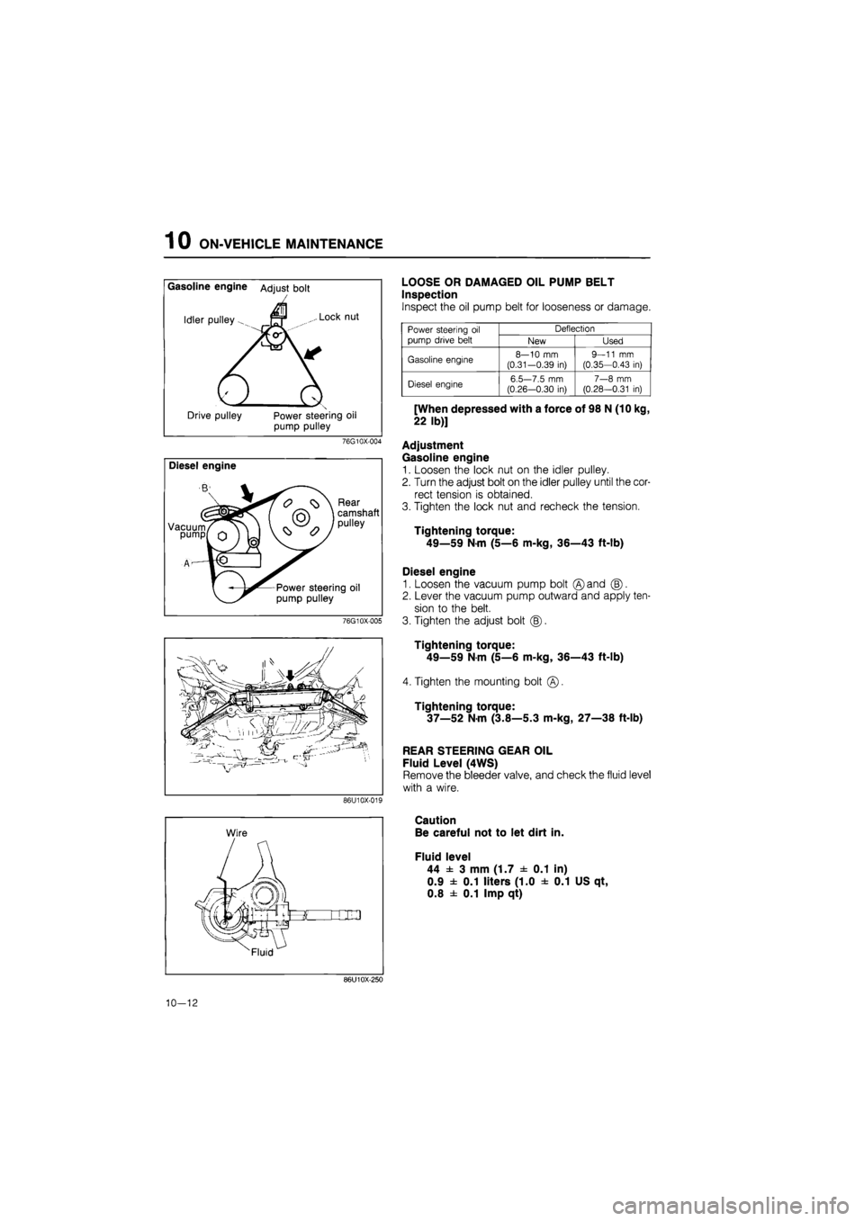
Gasoline engine Adjust bolt
Idler pulley fM ,.. Lock nut
1 / I
Drive pulley Power steering oil
pump pulley
76G10X-004
Diesel engine
Vacuum pump
Rear
camshaft
pulley
Power steering oil
pump pulley
76G10X-005
86U10X-019
LOOSE OR DAMAGED OIL PUMP BELT
Inspection
Inspect the oil pump belt for looseness or damage.
Power steering
oil
pump drive belt
Deflection Power steering
oil
pump drive belt New Used
Gasoline engine 8—10
mm
(0.31-0.39
in)
9—11
mm
(0.35—0.43
in)
Diesel engine 6.5—7.5
mm
(0.26—0.30
in)
7—8
mm
(0.28—0.31
in)
[When depressed with a force of 98 N (10 kg,
22 lb)]
Adjustment
Gasoline engine
1. Loosen the lock nut on the idler pulley.
2. Turn the adjust bolt on the idler pulley until the cor-
rect tension is obtained.
3. Tighten the lock nut and recheck the tension.
Tightening torque:
49—59 Nm (5—6 m-kg, 36—43 ft-lb)
Diesel engine
1. Loosen the vacuum pump bolt ©and (B).
2. Lever the vacuum pump outward and apply ten-
sion to the belt.
3. Tighten the adjust bolt (|).
Tightening torque:
49—59
N
m (5—6 m-kg, 36—43 ft-lb)
4. Tighten the mounting bolt
Tightening torque:
37—52 N-m (3.8—5.3 m-kg, 27—38 ft-lb)
REAR STEERING GEAR OIL
Fluid Level (4WS)
Remove the bleeder valve, and check the fluid level
with a wire.
Caution
Be careful not to let dirt in.
Fluid level
44 ± 3 mm (1.7 ± 0.1 in)
0.9 ± 0.1 liters (1.0 ± 0.1 US qt,
0.8 ± 0.1 Imp qt)
86U10X-250
10-12
Page 1304 of 1865
![MAZDA 626 1987 Workshop Manual
1 0 INSPECTION AND ADJUSTMENT
86U10X023
2WS
To oil pump
Si£r To gear housing
86U10X-024
86U10X-025
Thermometer [50—60°C (122—140°C)]
ii ^
Gauge
Close valve
completely
POWER STEERIN MAZDA 626 1987 Workshop Manual
1 0 INSPECTION AND ADJUSTMENT
86U10X023
2WS
To oil pump
Si£r To gear housing
86U10X-024
86U10X-025
Thermometer [50—60°C (122—140°C)]
ii ^
Gauge
Close valve
completely
POWER STEERIN](/manual-img/28/57059/w960_57059-1303.png)
1 0 INSPECTION AND ADJUSTMENT
86U10X023
2WS
To oil pump
Si£r To gear housing
86U10X-024
86U10X-025
Thermometer [50—60°C (122—140°C)]
ii ^
Gauge
Close valve
completely
POWER STEERING PRESSURE
1. Disconnect the high-pressure hose of the gear
housing side, and attach the SST.
Tightening torque:
39—49 N-m (4.0—5.0 m-kg, 29—36 ft-lb)
2. Bleed air from the system.
3. Open the gauge valve fully, then start the engine
and turn the steering wheel fully left and right to
raise the fluid temperature to 50—60°C
(122—140°F)
4. To measure the fluid pressure generated by the
oil pump, close the gauge valve completely and
increase the engine speed to 1,000—1,500 rpm.
If the fluid pressure is low, replace the oil pump
assembly.
Warning
If the valve is left closed for more than 15 sec-
onds, the fluid temperature will increase ex-
cessively and adversely affect the oil pump.
Oil pump fluid pressure
2WS
7,355—7,846 kPa
(75—80 kg/cm2, 1,066—1,138 psi)
4WS
Front 8,093—8,829 kPa
(82.5—90.0 kg/cm2, 1,173—1,280 psi)
Rear 7,112—7,848 kPa
(72.5—80.0 kg/cm2, 1,031—1,138 psi)
To measure the fluid pressure generated at the
gear housing, first open the gauge valve complete-
ly, increase the engine speed to 1,000—1,500
rpm, and then turn the steering wheel fully to the
left and right.
Warning
If the steering wheel is kept in the fully turned
position for more than 15 seconds, the fluid
temperature will rise excessively.
80U10X-026
10—16
Page 1305 of 1865
INSPECTION AND ADJUSTMENT 1 0
Thermometer [50—60°C (122—140°C)]
Gauge
(Turn steering wheel
completely
left/right)
Valve fully open
76G10X-032
Gear housing fluid pressure
2WS
7,355—7,846 kPa
(75—80 kg/cm2, 1,066—1,138 psi)
4WS
Front 8,093—8,829 kPa
(82.5—90.0 kg/cm2, 1,173—1,280 psi)
Rear More than 2,943 kPa
(More than 30 kg/cm2, more than 427 psi)
If the fluid pressure is low, repair or replace the gear
box.
6. Remove the gauge set, then tighten the high-
pressure hose to the specified torque.
Tightening torque:
31—36 Nm (3.2—3.7 m-kg, 23—27 ft-lb)
7. Bleed the air from the system. (Refer to page
10-15.)
10—17
Page 1306 of 1865
1 0 TIE-ROD END BOOT
TIE-ROD END BOOT
REMOVAL AND INSTALLATION
1. Jack up the vehicle and support it with safety stands.
2. Remove in the sequence shown in the figure, referring to the removal note for specially marked parts.
3. Install in the reverse order of removal, referring to the installation note for specially marked parts.
4. Tighten all nuts and bolts to the specified torque, referring to the figure.
Front
69—9S N m (7.0—10.0 m-kg, 51—72 ft-lb}
29—44 N-m (3.0—4.5 m-kg, 22—33 ft-lb)
88—118 N-m (9.0—12.0 m-kg, 65—87 ft-lb)
1. Lug nuts
2. Wheel
3. Tie-rod end
4. Nut
5. Boot
86U10X-028
Rear (4WS)
69—98 N-m (7.0—10.0 m-kg, 51—72 ft-lb)
29—44 N m (3.0—4.5 m-kg, 22-33 ft-lb)
88—118 N-m (9.0—12.0 m-kg, S5—87 ft-lb)
86U10X-029
1. Lug nuts
2. Wheel
3. Tie-rod end
4. Nut
5. Boot
10—18
Page 1315 of 1865
STEERING WHEEL AND COLUMN 1 0
INSTALLATION
Install in the reverse order of removal, referring to the installation note for specially marked parts.
Torque specifications
39—49
N m
(4.0—5.0 m-kg, 29—36 ft-lb)
86U10X-049
1. Combination switch
10-27
Page 1318 of 1865
1 0 STEERING GEAR AND LINKAGE
INSTALLATION
Install in the reverse order of removal.
Torque Specifications
18—26 Nm (1.8—2.7 m-kg, 13—20 ft-lb)
(3.0—4.5 m-kg, 22—33 ft-lb)
86U10X-055
10—30
Page 1323 of 1865

4-WHEEL STEERING GEAR AND LINKAGE 1 0
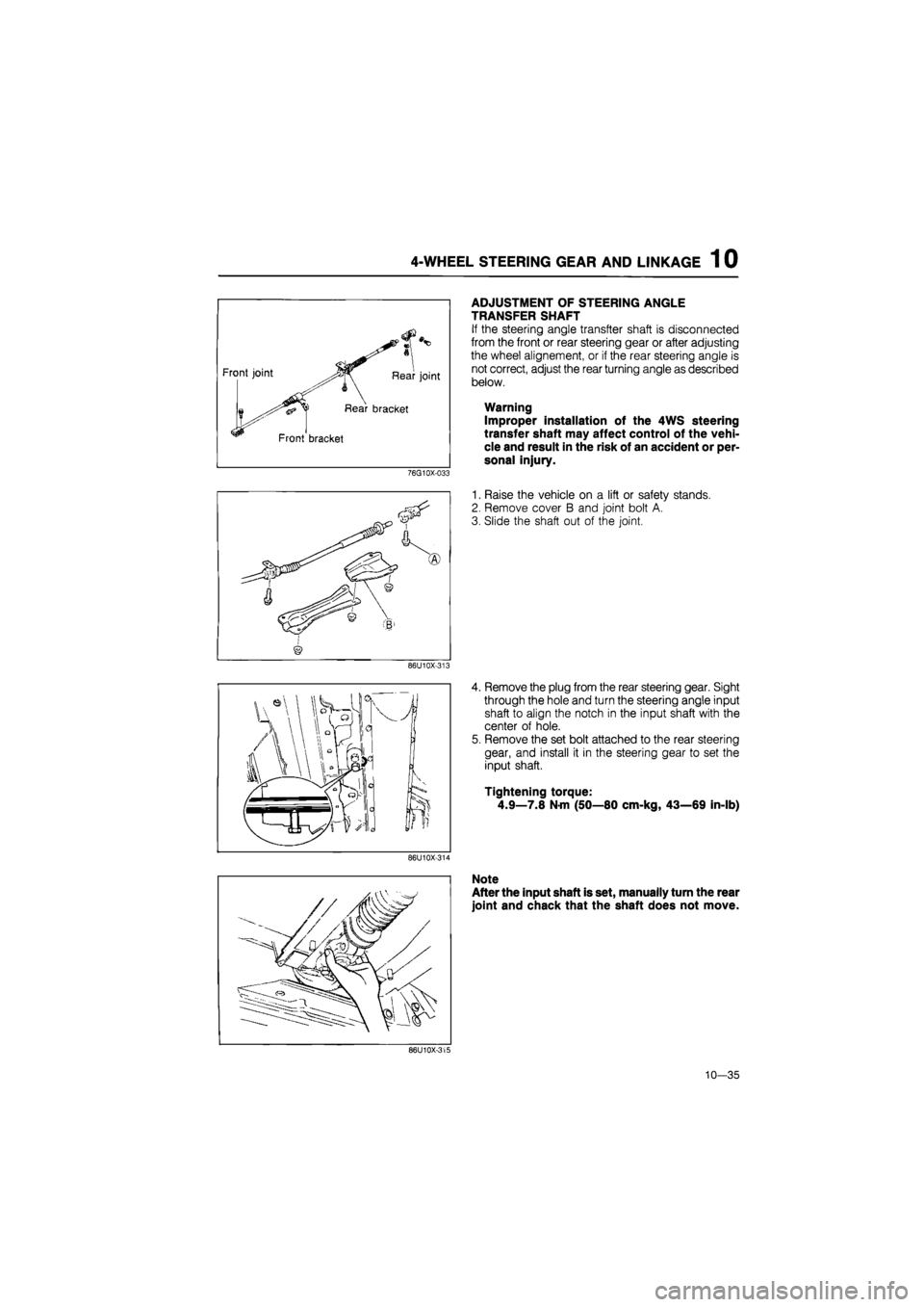
Front joint Rear joint
Rear bracket
Front bracket
76G10X-033
86U10X-313
ADJUSTMENT OF STEERING ANGLE
TRANSFER SHAFT
If the steering angle transfter shaft is disconnected
from the front or rear steering gear or after adjusting
the wheel alignement, or if the rear steering angle is
not correct, adjust the rear turning angle as described
below.
Warning
Improper installation of the 4WS steering
transfer shaft may affect control of the vehi-
cle and result in the risk of an accident or per-
sonal injury.
1. Raise the vehicle on a lift or safety stands.
2. Remove cover B and joint bolt A.
3. Slide the shaft out of the joint.
4. Remove the plug from the rear steering gear. Sight
through the hole and turn the steering angle input
shaft to align the notch in the input shaft with the
center of hole.
5. Remove the set bolt attached to the rear steering
gear, and install it in the steering gear to set the
input shaft.
Tightening torque:
4.9—7.8 N-m (50—80 cm-kg, 43—69 in-lb)
86U10X-314
Note
After the input shaft is set, manually turn the rear
joint and chack that the shaft does not move.
86U10X-315
10—35
Page 1324 of 1865
1 0 4-WHEEL STEERING GEAR AND LINKAGE
6. Lower the vehicle.
7. Check and adjust the front and rear wheel align-
ment if necessary. (Refer to Section 13.)
8. Drive the vehicle and mark the steering straight-
ahead position.(Refer to page 10—32.)
86U10B-316
9. Install the shaft and rear joint removed at step 2,
and tighten the bolt to the specified torque.
Tightening torque: 22—30 N-m
(2.2—3.1 m-kg, 191—269 in-lb)
10. Install and tighten a new wire on the joint boot.
86U10X-317
11. Install the set bolt in the rear steering gear.
Tightening torque:
20—28 N-m (2.0—2.9 m-kg, 14—21 ft-lb)
After installing the steering angle transfer
shaft, check the steering angle transfer shaft
alignment. [Refer to page 10—32 (Simple in-
spection).]
86U10X-318
10—36