Page 1167 of 1865
DISASSEMBLY 7C
76G07C-126
76G07C-127
86U07B-169
-fct
„ 1 / V.
Bearing race
49 FT01 361
5. Remove the idle gear assembly and output gear
assembly by tapping out from the torque convert-
er side.
6. Remove the bearing cover.
(1) Remove the converter housing from the trans-
axle hanger.
(2) Remove the bearing cover bolts.
(3) Press the bearing cover assembly out of the
converter housing.
7. Press the bearing outer race out of the converter
housing with the SST.
Note
Install the bearing outer race during reassem-
bly to adjust the preload.
8. Check the oil seals for damage. Replace if
necessary.
76G07C-128
7C-53
Page 1168 of 1865

7C INSPECTION AND REPAIR
INSPECTION AND REPAIR
PRECAUTION
(1) Several of the parts resemble each other; organize them so that they do not get mixed up.
(2) Clean each part with cleaning oil, clean out the oil holes and oil passages with compressed air,
and check that there are no obstructions.
(3) When using cleaning oil and compressed air, wear protective eyewear.
(4) If a clutch plate or brake band is replaced with a new one, soak it in ATF for 2 hours or more
before installing.
(5) Before assembly, apply ATF to all seal rings, rotating parts, and sliding parts.
(6) All seals, gaskets and roll pins must be replaced with new ones during assembly.
(7) Use petroleum jelly, not grease where required.
(8) When it is necessary to replace a bushing, replace the assembly which includes that bushing.
76G07C-353
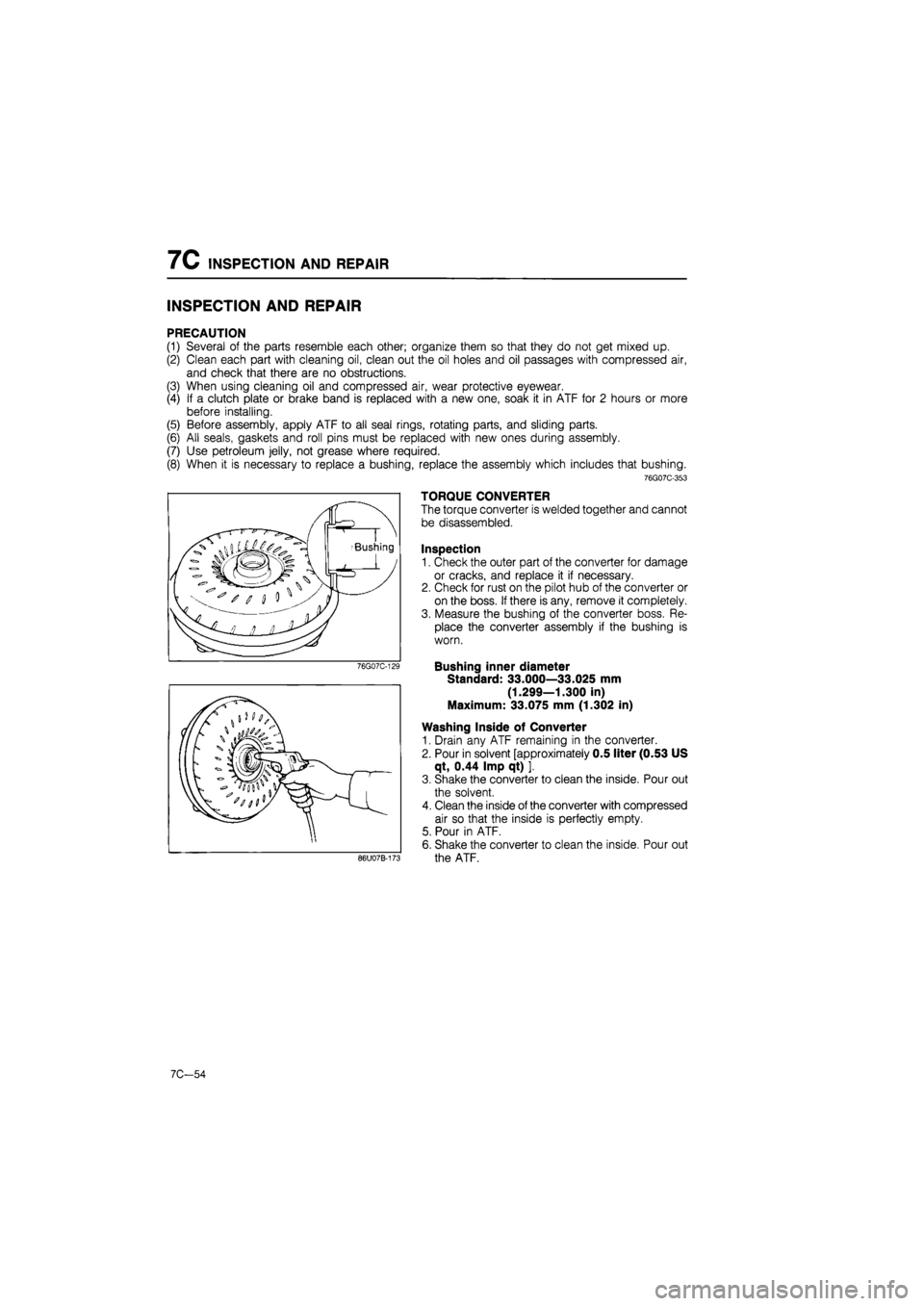
TORQUE CONVERTER
The torque converter is welded together and cannot
be disassembled.
Inspection
1. Check the outer part of the converter for damage
or cracks, and replace it if necessary.
2. Check for rust on the pilot hub of the converter or
on the boss. If there is any, remove it completely.
3. Measure the bushing of the converter boss. Re-
place the converter assembly if the bushing is
worn.
Bushing inner diameter
Standard: 33.000—33.025 mm
(1.299—1.300 in)
Maximum: 33.075 mm (1.302 in)
Washing Inside of Converter
1. Drain any ATF remaining in the converter.
2. Pour in solvent [approximately 0.5 liter (0.53 US
qt, 0.44 Imp qt) ].
3. Shake the converter to clean the inside. Pour out
the solvent.
4. Clean the inside of the converter with compressed
air so that the inside is perfectly empty.
5. Pour in ATF.
6. Shake the converter to clean the inside. Pour out
the ATF.
7C-54
Page 1171 of 1865
INSPECTION AND REPAIR 7C
76G07C-135
76G07C-136
76G07C-137
Assembly
1. Assemble so that the marks on the inner and out-
er gears are at the pump cover side.
2. Install the pump flange.
3. Install the oil pump cover.
Tightening torque: 11—14 N-m
(110—140 cm-kg, 95—122 in-lb)
4. Install the seal rings.
Seal ring outer diameter
A: 44 mm (1.732 in)
B: 43 mm (1.693 in)
5. When the assembly is completed, install the oil
pump shaft and make sure the gears turn easily.
76G07C-138
7C—57
Page 1188 of 1865
7C INSPECTION AND REPAIR
8. Install the filter into the separate plate.
76G07C-198
10. Secure the governor in the vise; tighten the gover-
nor body mounting bolts to the specified torque.
Tightening torque:
8—11 N
m
(80—110 cm-kg, 69—95 in-lb)
Note
Use protective plates in the vice to prevent
damage to the governor.
76G07C-199
11. Check that when compressed air is blown through
port A, the valve functions (rattles).
Air Pressure:
491 kPa (5.0 kg/cm2, 71 psi) max.
Caution
Apply air for no more than 5 seconds.
76G07C-200
7C—74
Page 1191 of 1865

INSPECTION AND REPAIR 7C
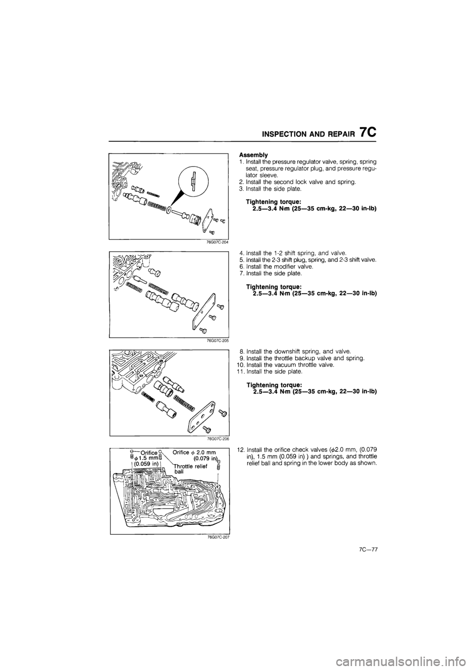
Assembly
1. Install the pressure regulator valve, spring, spring
seat, pressure regulator plug, and pressure regu-
lator sleeve.
2. Install the second lock valve and spring.
3. Install the side plate.
Tightening torque:
2.5—3.4 Nm (25—35 cm-kg, 22—30 in-lb)
76G07C-204
w
Install the 1-2 shift spring, and valve.
Install the 2-3 shift plug, spring, and 2-3 shift valve.
Install the modifier valve.
Install the side plate.
Tightening torque:
2.5—3.4 Nm (25—35 cm-kg, 22—30 in-lb)
76G07C-205
8. Install the downshift spring, and valve.
9. Install the throttle backup valve and spring.
10. Install the vacuum throttle valve.
11. Install the side plate.
Tightening torque:
2.5—3.4 N m (25—35 cm-kg, 22—30 in-lb)
76G07C-206
®—Orifice
©
1.5 mm | (0.059 in)j 1 fT—•sj-
Orifice 4> 2.0 mm
(0.079 in),
Throttle relief baii
'0
12. Install the orifice check valves (02.0 mm, (0.079
in), 1.5 mm (0.059 in)) and springs, and throttle
relief ball and spring in the lower body as shown.
76G07C-207
10,-11
Page 1192 of 1865
7C INSPECTION AND REPAIR
—® Orifice 2.0 mm (0.079 in)
76G07C-208
76G07C-209
76G07C-210
imru . ^P^l
o
o o o
13. Install the orifice check valve (<£2.0 mm (0.079 in))
in the upper body as shown.
14. Install the separator plate on the lower body, and
hold it with clips; then install them onto the upper
body.
15. Tighten the mounting bolts to the specified torque.
Tightening torque:
A: 2.5—3.4 N-m (25—35 cm-kg, 22—30 in-lb)
B: 5—7 N m (50—70 cm-kg, 43—61 in-lb)
16. Install the oil strainer.
Tightening torque:
3—4 Nm (30—40 cm-kg, 26—35 in-lb)
17. Turn the valve body assembly over, and install the
sub-body.
Tightening torque:
2.5—3.4 N-m (25—35 cm-kg, 22—30 in-lb)
18. Install the manual valve.
76G07C-211
7C-78
Page 1199 of 1865

INSPECTION AND REPAIR 7C
n Notches
m
«
m
«
i * •"-=- —*
76G07C-218
49FT01 439
86U07B-345
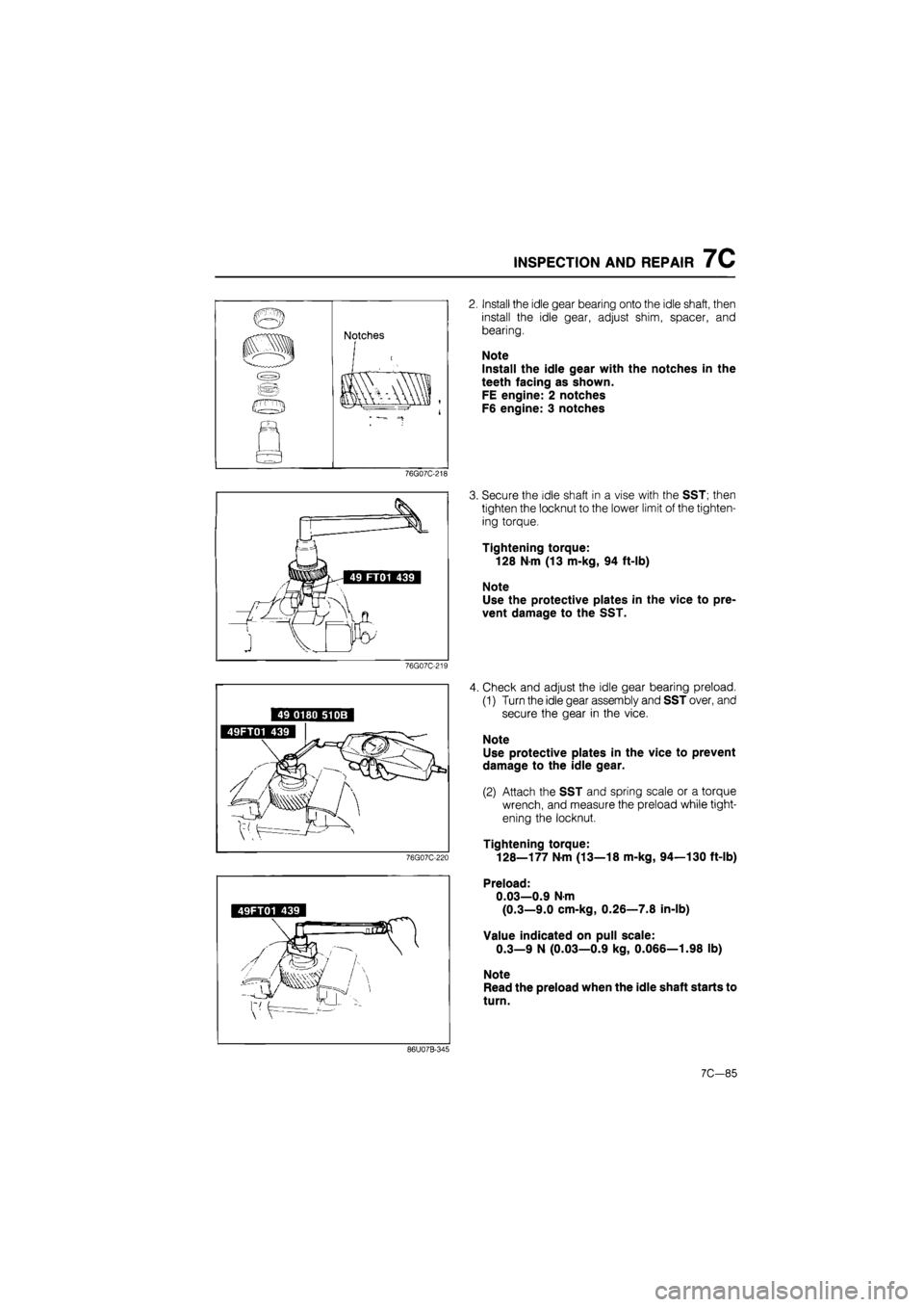
Install the idle gear bearing onto the idle shaft, then
install the idle gear, adjust shim, spacer, and
bearing.
Note
Install the idle gear with the notches in the
teeth facing as shown.
FE engine: 2 notches
F6 engine: 3 notches
Secure the idle shaft in a vise with the SST; then
tighten the locknut to the lower limit of the tighten-
ing torque.
Tightening torque:
128 N-m (13 m-kg, 94 ft-lb)
Note
Use the protective plates in the vice to pre-
vent damage to the SST.
Check and adjust the idle gear bearing preload.
(1) Turn the idle gear assembly and SST over, and
secure the gear in the vice.
Note
Use protective plates in the vice to prevent
damage to the idle gear.
(2) Attach the SST and spring scale or a torque
wrench, and measure the preload while tight-
ening the locknut.
Tightening torque:
128—177 N-m (13—18 m-kg, 94—130 ft-lb)
Preload:
0.03—0.9 Nm
(0.3—9.0 cm-kg, 0.26—7.8 in-lb)
Value indicated on pull scale:
0.3—9 N (0.03—0.9 kg, 0.066—1.98 lb)
Note
Read the preload when the idle shaft starts to
turn.
7C—85
Page 1200 of 1865
7C INSPECTION AND REPAIR
76G07C-221
5. If the specified preload can not be obtained with-
in the specified tightening torque, adjust it by select-
ing the proper adjust shims.
Thickness of shim
0.10 mm (0.004 in) 0.12 mm (0.005 in) 0.14 mm (0.006 in) 0.16 mm (0.0063 in) 0.20 mm (0.008 in) 0.50 mm (0.020 in)
Note
a) The maximum allowable number of shims
is 7.
b) Preload is reduced by increasing the thick-
ness of the shims, or increased by reduc-
ing the thickness of the shims.
BEARING COVER ASSEMBLY
Disassembly
Disassemble in the sequence shown in the figure, referring to the disassembly note for specially marked
part.
1. Oil seal
2. Bearing outer
race
3. O-ring
4. Bearing cover
76G07C-222
7C—86
expert22 .q/ifl http://rutracker.org