Page 1372 of 1865
1 0 OIL PUMP
4WS
16—23 N-m (1,6-2.3 m-kg, 12-17 ft-lb)
39—59 N m (4.0—6.0 m-kg, Z9—43 ft-lb)
37—52 N-m (3.8—5.3 m-kg, 27—38 ft-lb^.
(1.6-2,3 m-kg, 12-17 lt-!b)
31—46 N-m (3.2—4.7 m-kg, 23—34 ft-lb)
88—98 N-m (9.0—10.0 m-kg, 65—72 ft-lb)
49—59 N-m (5.0—6.0 m-kg, 36—43 ft-lb)
1. Belt
2. Nut
3. Pipes
4. Bracket
5. Oil pump
6. Oil pump pulley
Removal Note
Oil pump (2WS Gasoline engine, 4WS)
1. Hold the oil pump pulley with the SST, and remove
the pulley nut.
2. Slide the pulley forward. Remove the hose, pipes,
and the pump.
3. Remove the pulley.
76G10X-016
10—84
Page 1373 of 1865
1 0 OIL PUMP
2WS (Diesel engine, without CX)
78—11 N>m (D.e—1.1 m-kg, 5.6—8.0 ft-lb}
49-59 N-m (5.0—6.0 m-kg, 36—43 ft-lb)
76G10X-042
1. Drive belt cover
2. Belt
3. Nut
4. Oil pump pulley
5. Pipes
6. Bolt
7. Bolt
10-85
Page 1374 of 1865
1 0 OIL PUMP
2WS (Diesel engine, with CX)
r.a-11 N-m (0-8—1.1 m-kg. 5.8—8.0 tt-lb)
7.8—11 Nm (0,8—1.1 m-kg, 5.8—8.0 ft-lb)
7.8—11 Nm (0.8-1.1 m-kg, 5.8-8.0 ft-lb)
C3DSP-J
39-59 N-m (ED (4,0—6.0 m-kg, (7) ZB—43 ft-lb)
49—59 N m (5.0—6.0 m-kg, 36—43 ft-lb)
37—62 N-m (3.8—S.3 m-kg, 27—38 ft-lb)
76G10X-017
1. Drive belt cover
2. Belt
3. Cooling fan
4. Intake air pipe
5. Nut
6. Oil pump pulley
7. Pipes
8. Bolt
9. Starter
10. Bolt
Removal Note
Oil pump (2WS Diesel engine)
1. Hold the oil pump pulley with the SST, and remove
the pulley nut.
2. Slide the pulley forward. Remove the hose, pipes,
and the pump. 3. Remove the pulley.
76G10X-018
10—86
Page 1428 of 1865

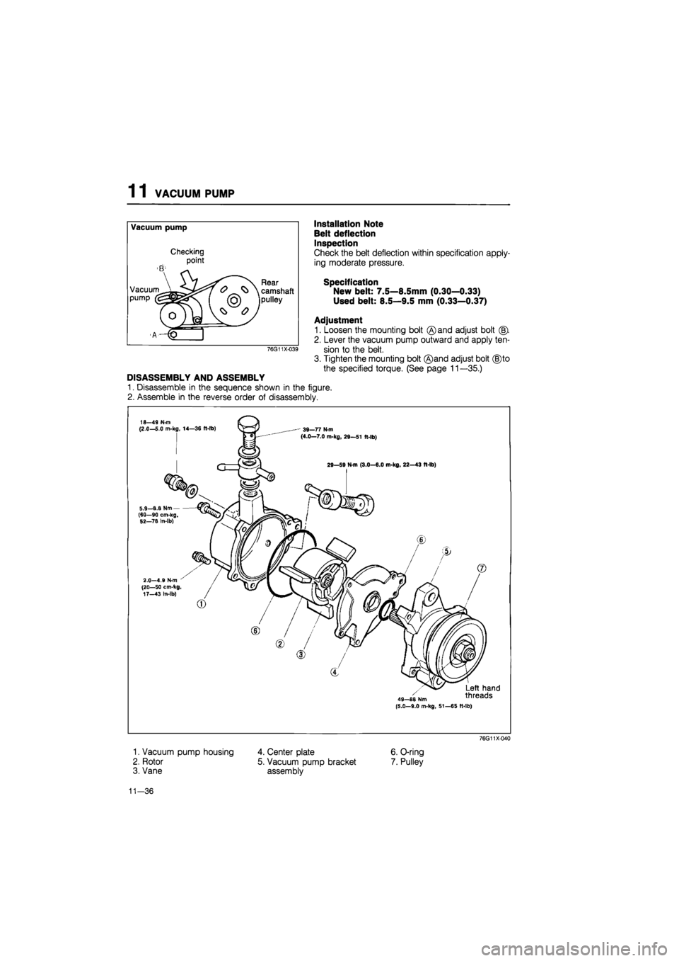
1 1 VACUUM PUMP
Vacuum pump
Checking
point
B -
VacuumA^^^^ pump [
(o) y
©
Rear
\ camshaft
jpulley
AHP"
76G11X-039
DISASSEMBLY AND ASSEMBLY
1. Disassemble in the sequence shown in the figure.
2. Assemble in the reverse order of disassembly.
Installation Note
Belt deflection
Inspection
Check the belt deflection within specification apply-
ing moderate pressure.
Specification
New belt: 7.5—8.5mm (0.30—0.33)
Used belt: 8.5—9.5 mm (0.33—0.37)
Adjustment
1. Loosen the mounting bolt ©and adjust bolt (§).
2. Lever the vacuum pump outward and apply ten-
sion to the belt.
3. Tighten the mounting bolt ®and adjust bolt (§)to
the specified torque. (See page 11 —35.)
18—49 N-m (2.0—5.0 m-kg, 14—36 ft-lb) ' 39—77 N-m (4.0—7.0 m-kg, 29—51 ft-lb)
29—59 N-m (3.0—6.0 m-kg, 22—43 ft-lb)
,_B.B Nm--90 cm-kg, 5.9 (60 52—78 In-lb)
2.0—4.9 N-m (20—50 cm-kg, 17—43 In-lb)
49—88 Nm (5.0-9.0 m-kg, 51—65 It-lb)
Left hand threads
1. Vacuum pump housing
2. Rotor
3. Vane
76G11X-040
4. Center plate
5. Vacuum pump bracket
assembly
6. O-ring
7. Pulley
11-36
Page 1552 of 1865

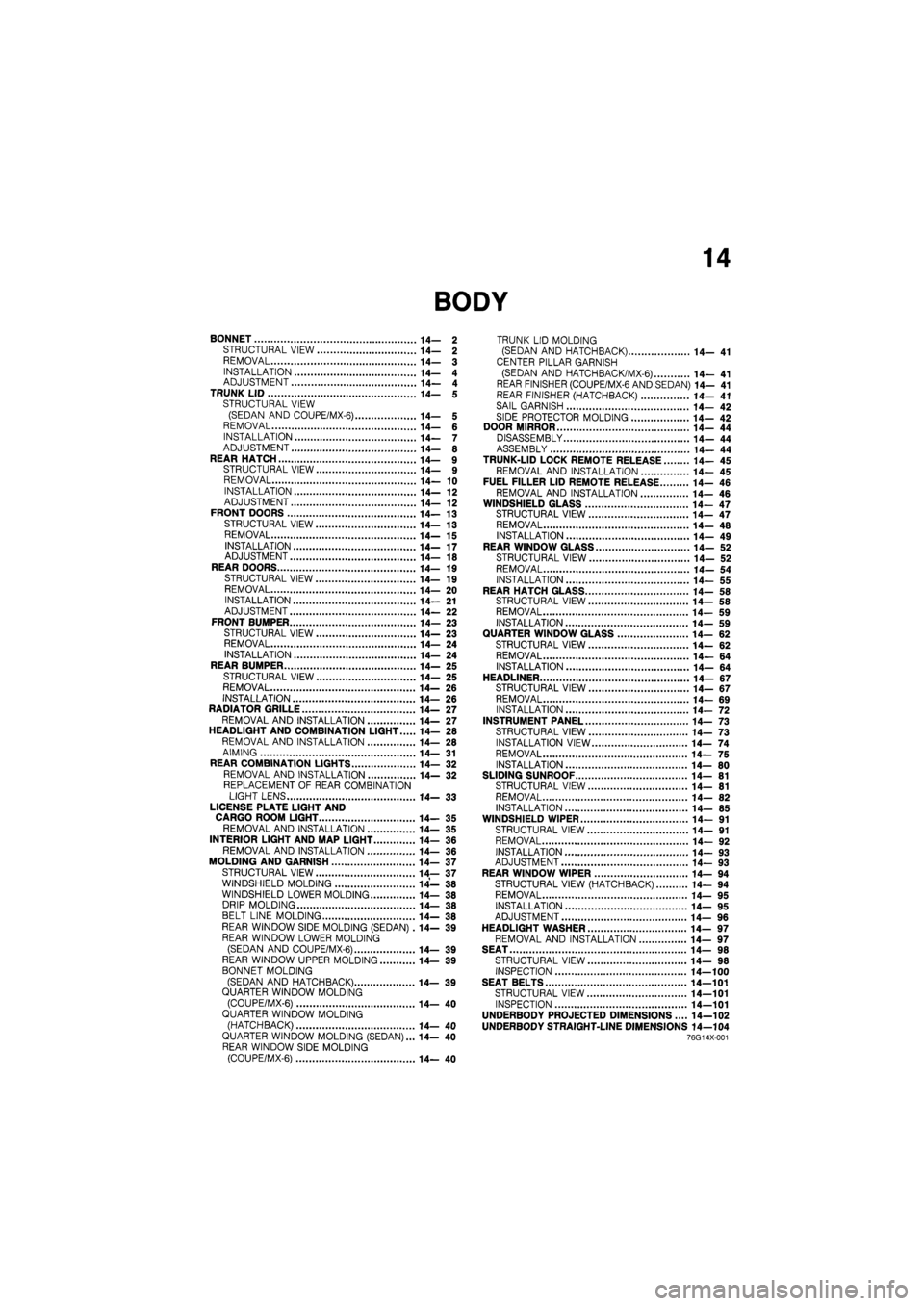
14
BONNET 14— 2
STRUCTURAL VIEW 14— 2
REMOVAL 14— 3
INSTALLATION 14— 4 ADJUSTMENT 14— 4 TRUNK LID 14— 5 STRUCTURAL VIEW (SEDAN AND COUPE/MX-6) 14— 5 REMOVAL 14— 6 INSTALLATION 14— 7 ADJUSTMENT 14— 8
REAR HATCH 14— 9 STRUCTURAL VIEW 14— 9 REMOVAL 14— 10 INSTALLATION 14— 12 ADJUSTMENT 14— 12 FRONT DOORS 14—13
STRUCTURAL VIEW 14— 13
REMOVAL 14—15
INSTALLATION 14—17 ADJUSTMENT 14— 18 REAR DOORS 14—19 STRUCTURAL VIEW 14— 19 REMOVAL 14— 20
INSTALLATION 14— 21 ADJUSTMENT 14— 22 FRONT BUMPER 14— 23
STRUCTURAL VIEW 14—23 REMOVAL 14— 24 INSTALLATION 14—24 REAR BUMPER 14— 25
STRUCTURAL VIEW 14— 25 REMOVAL 14— 26
INSTALLATION 14— 26 RADIATOR GRILLE 14— 27 REMOVAL AND INSTALLATION 14— 27 HEADLIGHT AND COMBINATION LIGHT 14— 28 REMOVAL AND INSTALLATION 14— 28
AIMING 14— 31 REAR COMBINATION LIGHTS 14— 32 REMOVAL AND INSTALLATION 14— 32
REPLACEMENT OF REAR COMBINATION LIGHT LENS 14— 33
LICENSE PLATE LIGHT AND CARGO ROOM LIGHT 14— 35 REMOVAL AND INSTALLATION 14— 35
INTERIOR LIGHT AND MAP LIGHT 14- 36 REMOVAL AND INSTALLATION 14— 36
MOLDING AND GARNISH 14— 37
STRUCTURAL VIEW 14— 37 WINDSHIELD MOLDING 14— 38 WINDSHIELD LOWER MOLDING 14— 38 DRIP MOLDING 14— 38 BELT LINE MOLDING 14— 38 REAR WINDOW SIDE MOLDING (SEDAN) .14— 39 REAR WINDOW LOWER MOLDING
(SEDAN AND COUPE/MX-6) 14— 39 REAR WINDOW UPPER MOLDING 14— 39
BONNET MOLDING
(SEDAN AND HATCHBACK) 14— 39 QUARTER WINDOW MOLDING (COUPE/MX-6) 14— 40 QUARTER WINDOW MOLDING
(HATCHBACK) 14—40 QUARTER WINDOW MOLDING (SEDAN)... 14— 40 REAR WINDOW SIDE MOLDING (COUPE/MX-6) 14— 40
TRUNK LID MOLDING (SEDAN AND HATCHBACK) 14— 41
CENTER PILLAR GARNISH
(SEDAN AND HATCH BAC K/MX-6) 14— 41 REAR FINISHER (COUPE/MX-6 AND SEDAN) 14— 41 REAR FINISHER (HATCHBACK) 14— 41
SAIL GARNISH 14— 42
SIDE PROTECTOR MOLDING 14— 42 DOOR MIRROR 14— 44 DISASSEMBLY 14— 44 ASSEMBLY 14— 44 TRUNK-LID LOCK REMOTE RELEASE 14— 45 REMOVAL AND INSTALLATION 14— 45 FUEL FILLER LID REMOTE RELEASE 14— 46
REMOVAL AND INSTALLATION 14— 46 WINDSHIELD GLASS 14—47 STRUCTURAL VIEW 14—47 REMOVAL 14— 48 INSTALLATION 14— 49 REAR WINDOW GLASS 14— 52
STRUCTURAL VIEW 14— 52 REMOVAL 14— 54
INSTALLATION 14— 55 REAR HATCH GLASS 14— 58 STRUCTURAL VIEW 14— 58 REMOVAL 14— 59 INSTALLATION 14— 59 QUARTER WINDOW GLASS 14— 62 STRUCTURAL VIEW 14— 62
REMOVAL 14— 64 INSTALLATION 14—64
HEADLINER 14- 67 STRUCTURAL VIEW 14—67 REMOVAL 14— 69 INSTALLATION 14— 72 INSTRUMENT PANEL 14— 73 STRUCTURAL VIEW 14— 73
INSTALLATION VIEW 14— 74
REMOVAL 14— 75 INSTALLATION 14— 80 SLIDING SUNROOF 14— 81 STRUCTURAL VIEW 14— 81 REMOVAL 14— 82 INSTALLATION 14— 85 WINDSHIELD WIPER 14— 91
STRUCTURAL VIEW 14— 91
REMOVAL 14— 92
INSTALLATION 14— 93 ADJUSTMENT 14— 93 REAR WINDOW WIPER 14—94 STRUCTURAL VIEW (HATCHBACK) 14— 94 REMOVAL 14— 95 INSTALLATION 14—95 ADJUSTMENT 14— 96
HEADLIGHT WASHER 14— 97 REMOVAL AND INSTALLATION 14— 97 SEAT 14— 98 STRUCTURAL VIEW 14— 98 INSPECTION 14—100 SEAT BELTS 14—101
STRUCTURAL VIEW 14—101 INSPECTION 14—101
UNDERBODY PROJECTED DIMENSIONS.... 14—102 UNDERBODY STRAIGHT-LINE DIMENSIONS 14—104 76G14X-001
Page 1564 of 1865
FRONT DOORS 1 4
FRONT DOORS
STRUCTURAL VIEW
86U14X-034
1. Power window switch
2. Regulator handle
3. Inner handle cover
4. Door trim
5. Door screen
6. Weatherstrip
7. Regulator (power type)
8. Regulator (manual type)
9. Key cylinder
10. Glass
11. Glass guide
12. Runchannel
13. Weatherstrip
14. Glass guide
15. Door checker
16. Door
17. Outer handle
18. Door mirror
19. Beltline molding
20. Weatherstrip
21. Sail inner garnish
14—13
Page 1565 of 1865
1 4 FRONT DOORS
1. Regulator handle
2. Arm rest
3. Power window switch
4. Inner handle cover
5. Door trim
6. Door screen
7. Weatherstrip
8. Regulator (power type)
9. Regulator (manual type)
10. Glass guide
11. Glass
12. Runchannel
13. Weatherstrip
14. Door
15. Door checker
16. Beltline molding
17. Weatherstrip
18. Door mirror
19. Outer handle
20. Key cylinder
21. Sail inner garnish
86U14X-035
14—14
Page 1567 of 1865
1 4 FRONT DOORS
86U14X-060
86U14X-040
86U14X-041
6. Remove the beltline molding. (Refer to page
14-39)
7. Remove the door glass upward.
8. Remove the mounting bolts, and remove the regu-
lator through the service hole.
9. Remove the window motor mounting bolt, and re-
move the motor from the regulator (power window).
Removal of Outer Handle and Key Cylinder
1. Disconnect the rod from the outer handle.
69G14X-036
14—16