Page 1614 of 1865
QUARTER WINDOW GLASS 14
Coupe/MX-6
86U14X-149
1. Seat belt bolts
2. Screw
3. Screw
4. Side trim
5. Screw
6. Rear pillar trim
7. Nut
8. Screw
9. Drip molding
10. Quarter window molding
11. Quarter window glass
12. Dam
14-63
Page 1621 of 1865
14 HEADLINER
10. Remove the caps and screws at the ends of the
front header trim.
86U14X-164
11. Remove the caps and screws at the ends of the
rear header trim.
86U14X-165
| 12. Remove the rear side trim.
86U14X-166
13. Remove the seat belt mounting bolts.
86U14X-167
14-70
Page 1652 of 1865
SEAT BELTS
1
4
SEAT BELTS
STRUCTURAL VIEW
76G14X-032
1. Buckles 3. Rear seat belts 5. Retractors
2. Front seat belts 4. Retractors
INSPECTION
1. Check that the belt can be pulled out smoothly and
that it retractors lock when belt pulled quickly.
2. Inspect the webbing for scars, tears, and wear and
for deformation of the fittings.
Caution
Do not disassemble the buckle or ELR as-
sembly.
14—101
Page 1692 of 1865
WARNING LIGHT AND SENDER 1 5
76G15X-090
Seat Belt Warning Light
76G15X-043
EC-AT Mode Indicator Light
POWER and ECONO indicator lights
do
not
il-
luminate.
NG
Check the hold switch. Refer
to
page 7B—63
NG
Replace the switch.
OK
NG
Check the mode switch. Refer
to
page 7B—63
NG
Replace the switch.
fOK
Replace the bulb
or
repair the harness (Meter
to
mode switch, EC-AT switch
to
control unit).
76G15X-091
76G15X-044
15—37
Page 1696 of 1865
CENTRAL PROCESSING UNIT (CPU) 1 5
CENTRAL PROCESSING UNIT (CPU)
STRUCTURAL VIEW
86U15X-071
FUNCTIONS
System Function
Sound Alarm System
Key reminder alarm
Sound Alarm System
Liaht-off reminder alarm
Sound Alarm System
Seat belt alarm
Timer System
Seat belt timer
Timer System
Kev illumination liaht timer
Timer System
Interior light timer
76G15X-008
15—41
Page 1697 of 1865
1 5 CENTRAL PROCESSING UNIT (CPU)
CIRCUIT DIAGRAM
-O-vO
I &
IG key
OFF
n\ Key reminder
Door ajar
warning light vf Door SW
llfl Engine control —_
unitj^"
Buckle SW
W7i
0
o
o
0
o
0
o
o
o
a
Q
u
n
dD
IG key
illumination light
[ Interior light
(f)
(f) (|)
teesy
J
cF Seat belt warning light
o o o 0 o o o
•a-
o o o o o o o
15-42
86U15X-073
Page 1698 of 1865

CENTRAL PROCESSING UNIT (CPU) 1 5
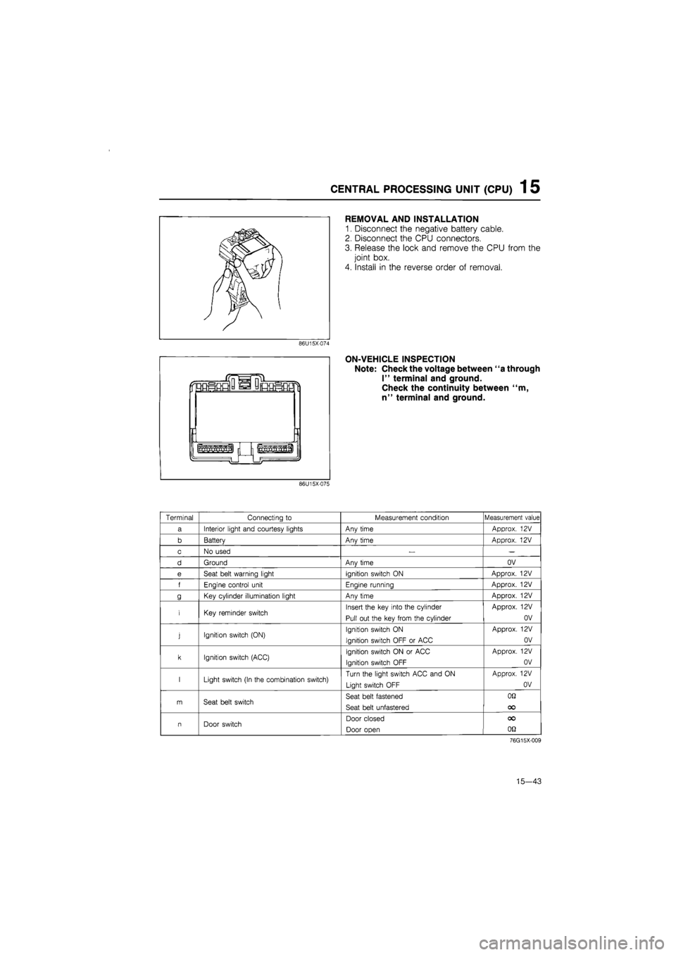
REMOVAL AND INSTALLATION
1. Disconnect the negative battery cable.
2. Disconnect the CPU connectors.
3. Release the lock and remove the CPU from the
joint box.
4. Install in the reverse order of removal.
ON-VEHICLE INSPECTION
Note: Check the voltage between "a through
I" terminal and ground.
Check the continuity between "m,
n" terminal and ground.
86U15X-075
Terminal Connecting
to
Measurement condition Measurement value
a Interior light and courtesy lights Any time Approx.
12V
b Batterv Anv time Approx.
12V
c No used
— —
d Ground Anv time OV
e Seat belt warning light Ignition switch
ON
Approx.
12V
f Enaine control unit Enaine runnina Approx.
12V
g Key cylinder illumination light Any time Approx.
12V
i Key reminder switch Insert the key into the cylinder
Pull out the key from the cylinder
Approx.
12V
OV
j Ignition switch (ON) Ignition switch
ON
Ignition switch OFF
or
ACC
Approx.
12V
OV
k Ignition switch (ACC) Ignition switch
ON or
ACC
Ignition switch OFF
Approx.
12V
OV
I Light switch (In the combination switch) Turn the light switch ACC and
ON
Light switch OFF
Approx.
12V
OV
m Seat belt switch Seat belt fastened
Seat belt unfastered
OQ
OO
n Door switch Door closed
Door open
OO
on
76G15X-009
15—43
Page 1788 of 1865

OUTLINE 16
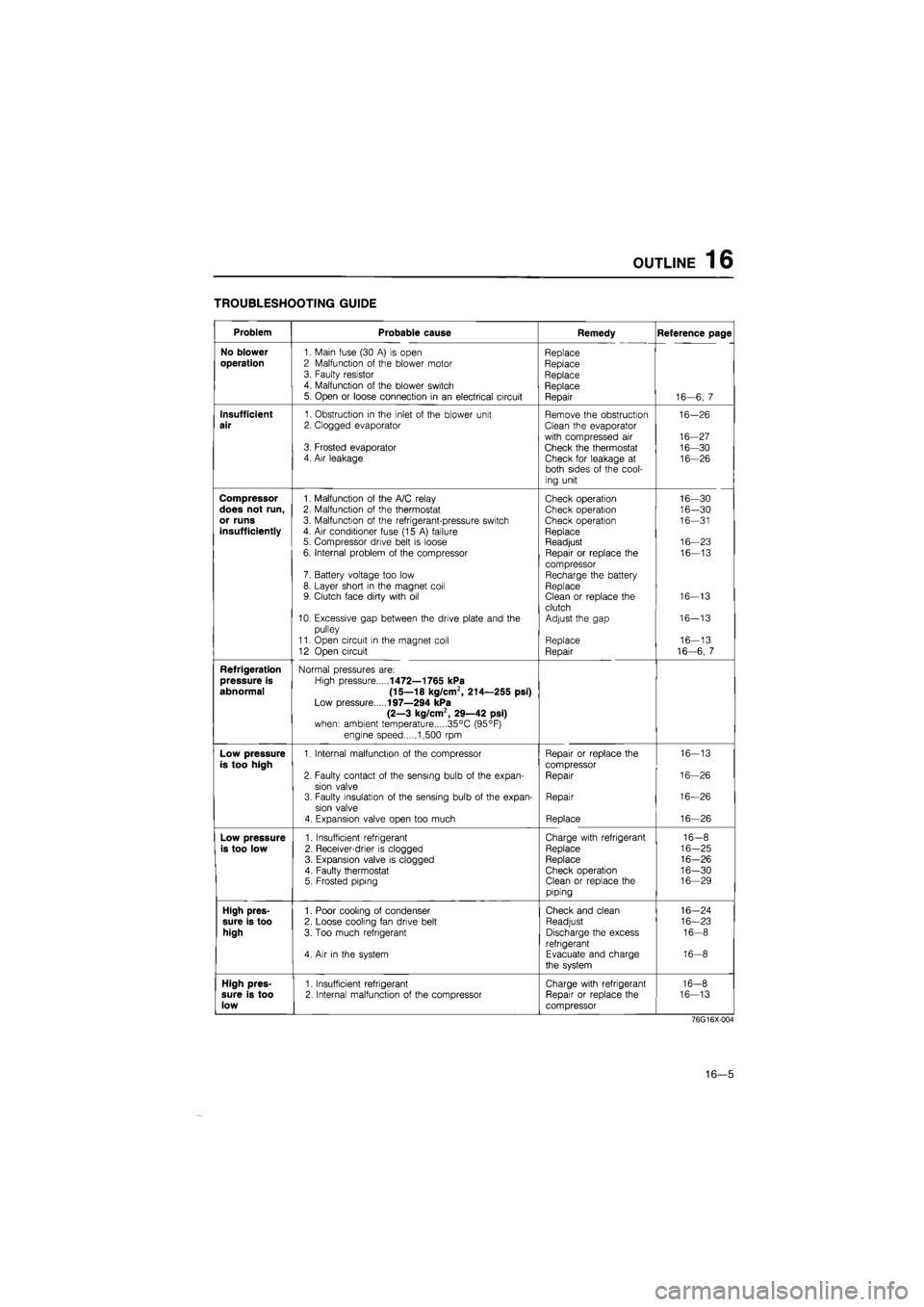
TROUBLESHOOTING GUIDE
Problem Probable cause Remedy Reference page
No blower
1. Main fuse (30
A) is
open Replace
operation
2 Malfunction
of
the blower motor Replace 3. Faulty resistor Replace 4. Malfunction
of
the blower switch Replace 5. Open
or
loose connection
in an
electrical circuit Repair 16—6,
7
Insufficient
1. Obstruction
in
the inlet
of
the blower unit Remove the obstruction 16-26
air
2. Clogged evaporator Clean the evaporator
with compressed
air
16-27 3. Frosted evaporator Check the thermostat 16-30 4. Air leakage Check for leakage
at
16-26 both sides
of
the cool-
ing unit
Compressor
1. Malfunction
of
the A/C relay Check operation 16—30
does not run,
2. Malfunction
of
the thermostat Check operation 16—30
or runs
3. Malfunction
of
the refrigerant-pressure switch Check operation 16—31
insufficiently
4.
Air
conditioner fuse (15
A)
failure Replace 5. Compressor drive belt
is
loose Readjust 16—23
6. Internal problem
of
the compressor Repair
or
replace
the
16—13
compressor 7. Battery voltage too low Recharge the battery 8. Layer short
in
the magnet coil Replace 9. Clutch face dirty with
oil
Clean
or
replace the 16-13
clutch 10. Excessive gap between the drive plate and
the
Adjust the gap 16-13
pulley
11. Open circuit
in
the magnet coil Replace 16—13
12 Open circuit Repair 16-6,
7
Refrigeration
Normal pressures are:
pressure is
High pressure
1472—1765 kPa
abnormal (15—18 kg/cm2, 214—255 psi)
Low pressure
197—294 kPa
(2—3 kg/cm2, 29—42 psi)
when: ambient temperature 35°C (95°F)
engine speed 1,500
rpm
Low pressure
1. Internal malfunction
of
the compressor Repair
or
replace the 16-13
is too high
compressor
2. Faulty contact
of
the sensing bulb
of
the expan-Repair 16-26
sion valve 3. Faulty insulation
of
the sensing bulb
of
the expan-Repair 16—26
sion valve
4. Expansion valve open too much Replace 16—26
Low pressure
1. Insufficient refrigerant Charge with refrigerant 16-8
is too low
2. Receiver-drier
is
clogged Replace 16-25
3. Expansion valve
is
clogged Replace 16-26
4. Faulty thermostat Check operation 16-30 5. Frosted piping Clean
or
replace the 16—29
piping
High pres-
1. Poor cooling
of
condenser Check and clean 16-24
sure is too
2. Loose cooling fan drive belt Readjust 16—23
high
3. Too much refrigerant Discharge the excess 16-8
refrigerant 4.
Air in
the system Evacuate and charge 16-8
the system
High pres-
1. Insufficient refrigerant Charge with refrigerant 16-8
sure is too
2. Internal malfunction
of
the compressor Repair
or
replace the 16-13
low
compressor
76G16X-004
16—5