1987 MAZDA 626 belt
[x] Cancel search: beltPage 713 of 1865

TROUBLESHOOTING GUIDE 5
TROUBLESHOOTING GUIDE
Problem Possible cause Remedy Page
Starter does not turn at all, or Its turning speed Is too slow to start the engine.
Battery and related parts Poor contact of battery terminals Poor grounding of negative cable Voltage drop caused by discharged battery Insufficient voltage caused by battery malfunction
Clean and tighten Clean and repair Recharge Replace
5- 8
5- 8 5- 8
Ignition switch and related parts Poor contact of ignition switch Loose ignition switch wiring or connector Broken wire between ignition switch and magnetic switch
Replace Repair Repair or replace 5-38,45,56,66
Magnetic switch and related parts Loose wiring and/or connectors Burnt magnetic switch contact plate or improper contact Broken wire in magnetic switch pull-in coil Broken wire magnetic switch holding coil
Repair Replace
Replace Replace
5-38,45,56,66 5-43,54,64,74
5-43,54,64,74 5-43,54.64,74
Starter Poor contact of brushes
Fatigued brush spring Poor grounding of field coil Poor soldering of field coil Commutator mulfunction Grounded armature Worn parts
Adjust contact or replace Replace Replace Repair Repair or Replace Replace Replace
5-43,54,64,74
Starting problem Gasoline engine Insufficient battery capacity Malfunction of spark plug (s)
Loose positive terminal Damaged distributor cap or rotor Ignition coil malfunction laniter malfunction
Recharge Clean, adjust or replace Tighten Replace Replace Renlane
5— 8 5— 9
5—16 5—10 5-16,20
Diesel engine Insufficient battery capacity QSS svstem malfunction Recharge ReDlace 5— 8 5-76
Starter turns but pinion gear does not mesh with ring gear
Starter Tip of overrunning clutch pinion is worn Weakened overrunning clutch drive spring Worn overrunning clutch Improper sliding of spline
Worn bushing Worn ring gear
Replace Replace Replace Adjust contact and repair, or replace Replace ReDlace
5-40,54,70
Starter turns continuously (does not stop) Magnetic switch Sticking contact place of magnetic switch Layer shorting coil of magnetic switch Ignition switch does not return
Replace Replace Rfinlanfi
5-43,54,64,74 5-43,54,64,74
Misfiring Dirty or damaged spark plug (s) Malfunction of wiring, or open circuit Damaged distributor cap
Clean or replace Repair or Replace Replace
5- 9 5—10 5—16
Discharging of battery Alternator Loose drive belt Grounded or broken stator coil Broken rotor coil Poor contact of brush and slip ring
Malfunction of rectifier Malfunction of IC regulator Battery and related parts Insufficient or unsuitable battery electrolyte Malfunction of battery electrode (internal short-circuit) Poor contact of battery terminal (s) Excessive electric load
Adjust Replace Replace Clean, repair or replace Replace Replace
Adjust Replace
Clean and tighten Check power consump-tion and short circuit
5-37 5-32 5-32 5-32
5-34
5— 8 5- 8
5— 8
Overcharging of battery IC regulator malfunction Operating in extremely high temperature Replace Reoair
Poor acceleration Mis-adjusted ignition timing Distributor malfunction Adjust Repair or replace 5—11 5—11
Knocking Mis-adjusted ignition timing | Distributor malfunction Adjust Repair or replace 5—11 5—11
76G05X-003
5-7
Page 717 of 1865

DISTRIBUTOR 5
7BU05X-075
86U05X-048
76G05X-007
DISTRIBUTOR
SPARK TEST
1. Disconnect the distributor lead from the distributor.
2. Hold it with insulated pliers approx. 5—10 mm
(0.20—0.39 in) from a ground.
3. Crank the engine and check that a strong blue
spark is visible.
4. If there is no spark, the ignition coil or pick-up coil
may be bad.
Check once again after replacing the ignition coil
or pick-up coil.
IGNITION TIMING
1. Warm up the engine to the normal operating tem-
perature.
2. Turn all electric loads OFF.
3. Connect a tachometer and timing light to the
engine.
4. Connect a jumper wire between the test connec-
tor and ground. (Only for FE DOHC)
5. Check the idle speed. Set to the specified speed
if necessary.
Idle speed: 750 ± 50 rpm (FE DOHC)
800 t58 rpm (F6, F8 FE—MTX)
900 i58 rpm (F8, FE—ATX
in "P" range)
950 -5o rmp (F6—ATX
in "P" range)
6. Check that the timing mark (Yellow) on the crank-
shaft pulley and the mark on the timing belt cover
are aligned.
Ignition timing:
FE DOHC: 12 ± 1° BTDC
(Test connector grounded)
Others: 6 ± 1°
(Vacuum hoses disconnected and
plugged)
76G05X-008
5—11
Page 733 of 1865

ALTERNATOR 5
TEST 6
1. Turn the ignition switch ON.
2. Turn all electric loads off and release
the brake pedal.
3. Check that voltage between S terminal
and ground is battery voltage.
S terminal
76G05X-057
76G05X-030
86U05X-074
REMOVAL (GASOLINE)
Remove in the sequence shown in the figure.
1. Disconnect the negative battery terminal.
2. Disconnect the wire and connector from the al-
ternator.
3. Remove the bolts.
4. Remove the V-belt.
-5. Remove the alternator to upper side (LHD) or lower
side (RHD).
REMOVAL (DIESEL)
1. Disconnect the negative battery terminal.
2. Remove the right hand driveshaft (Refer to Sec-
tion 9).
3. Disconnect the wire and connector from the al-
ternator.
4. Loosen the idle pulley nuts and remove the drive
belts.
5. Remove the bolts and remove the alternator from
under the vehicle.
76G05X-031
5-27
Page 743 of 1865

ALTERNATOR 5
Adjusting bar bolt
Mounting bolt
Alternator
drive pulley
Mounting bolt
Drive pulley
76G05X-037
-Adjusting bolt
tidier pulley
v v Ml/v — Locknut
/
Alternator x
V-BELT TENSION (GASOLINE)
Adjustment
1. Loosen the alternator mounting bolt and adjusting
bar bolt.
2. Adjust the alternator belt deflection while pushing
the V-belt with a force of 98 N (10 kg, 22 ft-lb).
Deflection:
New: 6—8 mm (0.24—0.31 in)
Used: 7—9 mm (0.27—0.35 in)
3. Tighten the bolts and recheck the tension.
V-BELT TENSION (DIESEL)
Adjustment
1. Looson the alternator idler pulley locknut.
2. Adjust the alternator belt deflection while pushing
the V-belt with a force of 98 N (10 kg, 22 ft-lb).
Deflection:
Alternator
New: 8—10 mm (0.31—0.39 in)
Used: 9—11 mm (0.35—0.43 in)
76G05X-038
—" , ^Comprex pulley
/ Locknut
/ ^"Wvl If Adjusting bolt^
Idler pulley
Alternator pulley—-V-
(rear) >
Comprex
New: 4.0—5.0 mm (0.16—0.20 in)
Used: 4.5—5.5 mm (0.18—0.21 in)
3. Tighten the bolts and nuts and recheck the tension.
76G05X-058
5—37
Page 1289 of 1865

10
STEERING SYSTEM
OUTLINE 10— 2
STRUCTURAL VIEW 10— 2 SPECIFICATIONS 10— 6
TROUBLESHOOTING GUIDE 10— 7
MANUAL STEERING 10— 7
POWER STEERING 10— 8
4WS 10— 9
ON-VEHICLE MAINTENANCE 10— 10
STEERING WHEEL PLAY 10— 10
LOOSENESS OR PLAY OF THE
STEERING WHEEL 10— 10
STEERING WHEEL EFFORT 10— 10
POWER STEERING FLUID LEVEL 1 fl-11
LOOSE OR DAMAGED
OIL PUMP BELT IC— 12
REAR STEERING GEAR OIL 10— 12 LEAKAGE OF POWER STEERING
FLUID 10— 13
INSPECTION AND ADJUSTMENT. 10— 15
BLEEDING OF POWER STEERING
SYSTEM 10— 15
POWER STEERING PRESSURE ... 10— 16
TIE-ROD END BOOTS 10— 18
REMOVAL AND INSTALLATION .. 10— 18
STEERING WHEEL AND COLUMN 10— 21
STRUCTURAL VIEW 10— 21
REMOVAL 10— 22
DISASSEMBLY AND ASSEMBLY.. 10— 24
INSPECTION 10— 25
INSTALLATION 1 fl-27
STEERING GEAR AND LINKAGE .. IC— 28
STRUCTURAL VIEW 10— 28
REMOVAL 10— 29
INSTALLATION 10— 30
4-WHEEL STEERING GEAR AND
LINKAGE 10— 31
STRUCTURAL VIEW 10— 31 4WS PERFORMANCE INSPECTION 10— 32
ADJUSTMENT OF STEERING
ANGLE TRASFER SHAFT 10— 35
REMOVAL AND INSTALLATION .. 10— 37
INSPECTION 10— 44
MANUAL STEERING 10— 48
DISASSEMBLY 10— 48
INSPECTION 10— 51
ASSEMBLY 10— 52
ENGINE SPEED SENSING POWER
STEERING 10— 58
DISASSEMBLY 10— 58
INSPECTION 10— 62
ASSEMBLY 10— 64
ELECTRONICALLY-CONTROLLED
POWER STEERING 10— 75
DISASSEMBLY 10— 75
INSPECTION 10— 78
ASSEMBLY 10— 79
OIL PUMP 10— 83
REMOVAL AND INSTALLATION .. 10— 83
ELECTRICAL COMPONENTS OF
ELECTRONICALLY-CONTROLLED
POWER STEERING 10— 87
CIRCUIT DIAGRAM 10— 87
TROUBLESHOOTING GUIDE 10— 87
TROUBLESHOOTING 10— 87
ELECTRICAL COMPONENTS OF
4 WHEEL STEERING 10— 94
CIRCUIT DIAGRAM 10— 94
TROUBLESHOOTING GUIDE 10— 95
TROUBLESHOOTING 10— 95
4WS WARNING LIGHT 10—102
SPEED SENSOR (IN METER) 10—103
SPEED SENSOR (AT TRANSAXLE) 10—103
REAR-TO-FRONT STEERING
RATIO SENSOR 10—103
OIL LEVEL SWITCH
(IN P/S RESERVOIR) 10—103
RELAY AND TIMER 10—104 76G10X-001
Page 1296 of 1865

1 0 TROUBLESHOOTING GUIDE
POWER STEERING
Problem Possible cause Remedy Page
Hard steering
Loose
or
damaged belt Low fluid level,
or air in
fluid Leakage
of
fluid
Malfunctioning electrical system* Insufficient oil pump pressure Improperly adjusted wheel alignment Malfunctioning steering gear Linkage ball joint not operating smoothly
Adjust
or
replace Add fluid
or
bleed
air
Repair
or
replace Repair
or
replace Repair
or
replace Refer
to
Section
13
Repair
or
replace Replace
10—12 10-11 10-13 10-87 10-16
10—28,
37
10-18
Poor return
Insufficient tire pressure
Improperly adjusted wheel alignment
Ball-joint not operating smoothly
Steering shaft contacting something
Refer
to
Section
12
Refer
to
Section
13
Replace
Repair
10-20 10-21
Excessive play
Loose gear box housing mounting bolts Worn linkage
or
tie-rod ball joint Worn lower ball joint Worn
or
damaged steering joint Worn rack and pinion gear
Tighten Replace
Refer
to
Section
13
Replace
Replace
10—30
10—18
10—21
10-58,
75
Steering wheel
vibrates
Insufficient tire pressure Damaged
or
unbalanced wheel Improperly adjusted wheel alignment Loose gear box housing mounting bolts Incorrect pinion preload adjustment Worn ball joints
Loose shock absorber mounting Malfunctioning shock absorber
Refer
to
Section
12
Refer
to
Section
13
Refer
to
Section
13
Tighten Adjust
Replace Refer
to
Section
13
Refer
to
Section
13
10-30 10-72,
81
10—18
Steering wheel
pulls
Unevenly worn tires
Incorrect tire pressure
Dragging brake
Improperly adjusted wheel alignment
Refer
to
Section
12
Refer
to
Section
12
Refer
to
Section
11
Refer
to
Section
13 —
Excessively light
steering at high
speed*
Malfunctioning electrical system Repair
or
replace 10-87
*... Only
for
electronically
-
controlled type
76G10X-002
10—8
Page 1300 of 1865

1 0 ON-VEHICLE MAINTENANCE
Gasoline engine Adjust bolt
Idler pulley fM ,.. Lock nut
1 / I
Drive pulley Power steering oil
pump pulley
76G10X-004
Diesel engine
Vacuum pump
Rear
camshaft
pulley
Power steering oil
pump pulley
76G10X-005
86U10X-019
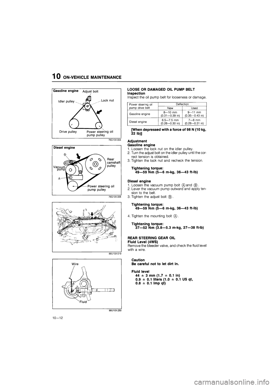
LOOSE OR DAMAGED OIL PUMP BELT
Inspection
Inspect the oil pump belt for looseness or damage.
Power steering
oil
pump drive belt
Deflection Power steering
oil
pump drive belt New Used
Gasoline engine 8—10
mm
(0.31-0.39
in)
9—11
mm
(0.35—0.43
in)
Diesel engine 6.5—7.5
mm
(0.26—0.30
in)
7—8
mm
(0.28—0.31
in)
[When depressed with a force of 98 N (10 kg,
22 lb)]
Adjustment
Gasoline engine
1. Loosen the lock nut on the idler pulley.
2. Turn the adjust bolt on the idler pulley until the cor-
rect tension is obtained.
3. Tighten the lock nut and recheck the tension.
Tightening torque:
49—59 Nm (5—6 m-kg, 36—43 ft-lb)
Diesel engine
1. Loosen the vacuum pump bolt ©and (B).
2. Lever the vacuum pump outward and apply ten-
sion to the belt.
3. Tighten the adjust bolt (|).
Tightening torque:
49—59
N
m (5—6 m-kg, 36—43 ft-lb)
4. Tighten the mounting bolt
Tightening torque:
37—52 N-m (3.8—5.3 m-kg, 27—38 ft-lb)
REAR STEERING GEAR OIL
Fluid Level (4WS)
Remove the bleeder valve, and check the fluid level
with a wire.
Caution
Be careful not to let dirt in.
Fluid level
44 ± 3 mm (1.7 ± 0.1 in)
0.9 ± 0.1 liters (1.0 ± 0.1 US qt,
0.8 ± 0.1 Imp qt)
86U10X-250
10-12
Page 1371 of 1865

OIL PUMP 1 0
OIL PUMP
REMOVAL AND INSTALLATION
1. Jack up the front of the vehicle, and support it with safety stands.
2. Remove in the order shown in the figure, referring to the removal note for specially marked parts.
3. Install in the reverse order of removal.
4. Tighten all nuts and bolts to the specified torque, referring to the figure.
Note
a) The power steering fluid will leak out when the return hose or the pressure hose is dis-
connected. Prepare a suitable container for it to drain into.
b) After installation, inspect the deflection of the oil pump belt and bleed the air from the
system, then check for fluid leakage. 2WS (Gasoline engine)
76G10X-041
4. Bracket
5. Oil pump
6. Oil pump pulley
1. Belt
2. Nut
3. Pipes
10—83