1987 MAZDA 626 belt
[x] Cancel search: beltPage 1796 of 1865
COMPRESSOR 16
69G16X-026
M10X1.25^45
Low-pressure x pressure
hose hose Compressor
COMPRESSOR
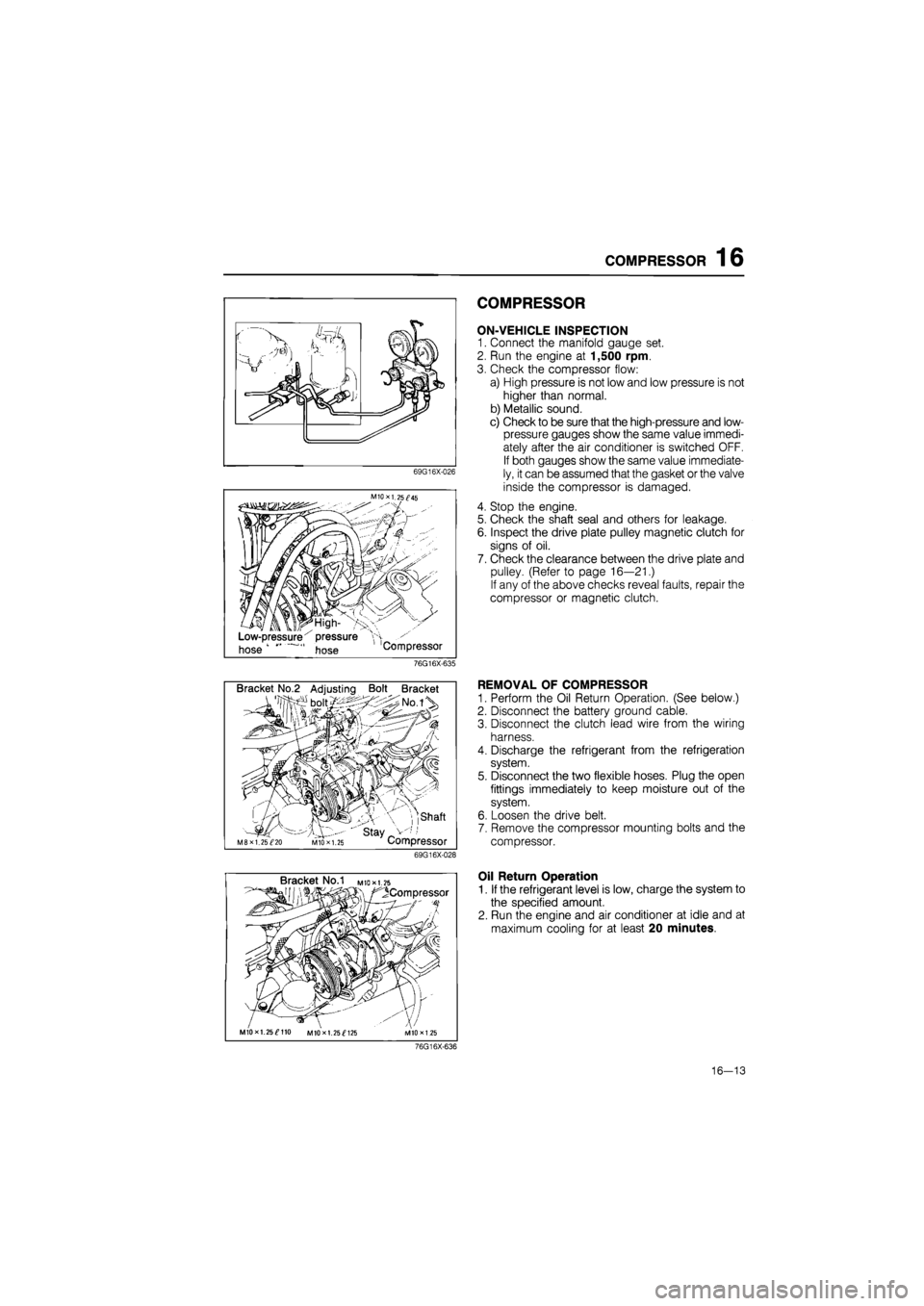
ON-VEHICLE INSPECTION
1. Connect the manifold gauge set.
2. Run the engine at 1,500 rpm.
3. Check the compressor flow:
a) High pressure is not low and low pressure is not
higher than normal.
b) Metallic sound.
c) Check to be sure that the high-pressure and low-
pressure gauges show the same value immedi-
ately after the air conditioner is switched OFF.
If both gauges show the same value immediate-
ly, it can be assumed that the gasket or the valve
inside the compressor is damaged.
4. Stop the engine.
5. Check the shaft seal and others for leakage.
6. Inspect the drive plate pulley magnetic clutch for
signs of oil.
7. Check the clearance between the drive plate and
pulley. (Refer to page 16—21.)
If any of the above checks reveal faults, repair the
compressor or magnetic clutch.
76G16X-635
Bracket No.2 Adjusting Bolt Bracket
, ,shaft
' stay _ M8XI. 25^20 MIO X 1.25 Compressor
69G16X-028
REMOVAL OF COMPRESSOR
1. Perform the Oil Return Operation. (See below.)
2. Disconnect the battery ground cable.
3. Disconnect the clutch lead wire from the wiring
harness.
4. Discharge the refrigerant from the refrigeration
system.
5. Disconnect the two flexible hoses. Plug the open
fittings immediately to keep moisture out of the
system.
6. Loosen the drive belt.
7. Remove the compressor mounting bolts and the
compressor.
Bracket No.1 M
to* 1.25
^Compressor
MIOxl. 25^110 MIOxl. 25^125
Oil Return Operation
1. If the refrigerant level is low, charge the system to
the specified amount.
2. Run the engine and air conditioner at idle and at
maximum cooling for at least 20 minutes.
76G16X-636
16—13
Page 1806 of 1865
COMPRESSOR 16
Bracket No/I mio*i.75
/^Compressor
V'
MIOxl.25^110 M10X1.25^125 M1DX1.2S
76G16X-618
Bracket No.2 Adjusting Bolt Bracket
• boit/:> X ;>No.iV
•S3-
f'f
// mi
I 1 I 1 Shaft
M8 x 1.25^20 • ' Stay V-;,' M10X1.25 Compressor 76G16X-619
V belt Turn the adjusting bolt
Compressor Adjusting bolt
76G16X-620
MIOxl. 25^45
Low-pressure' pressure "H
hose hose Compressor
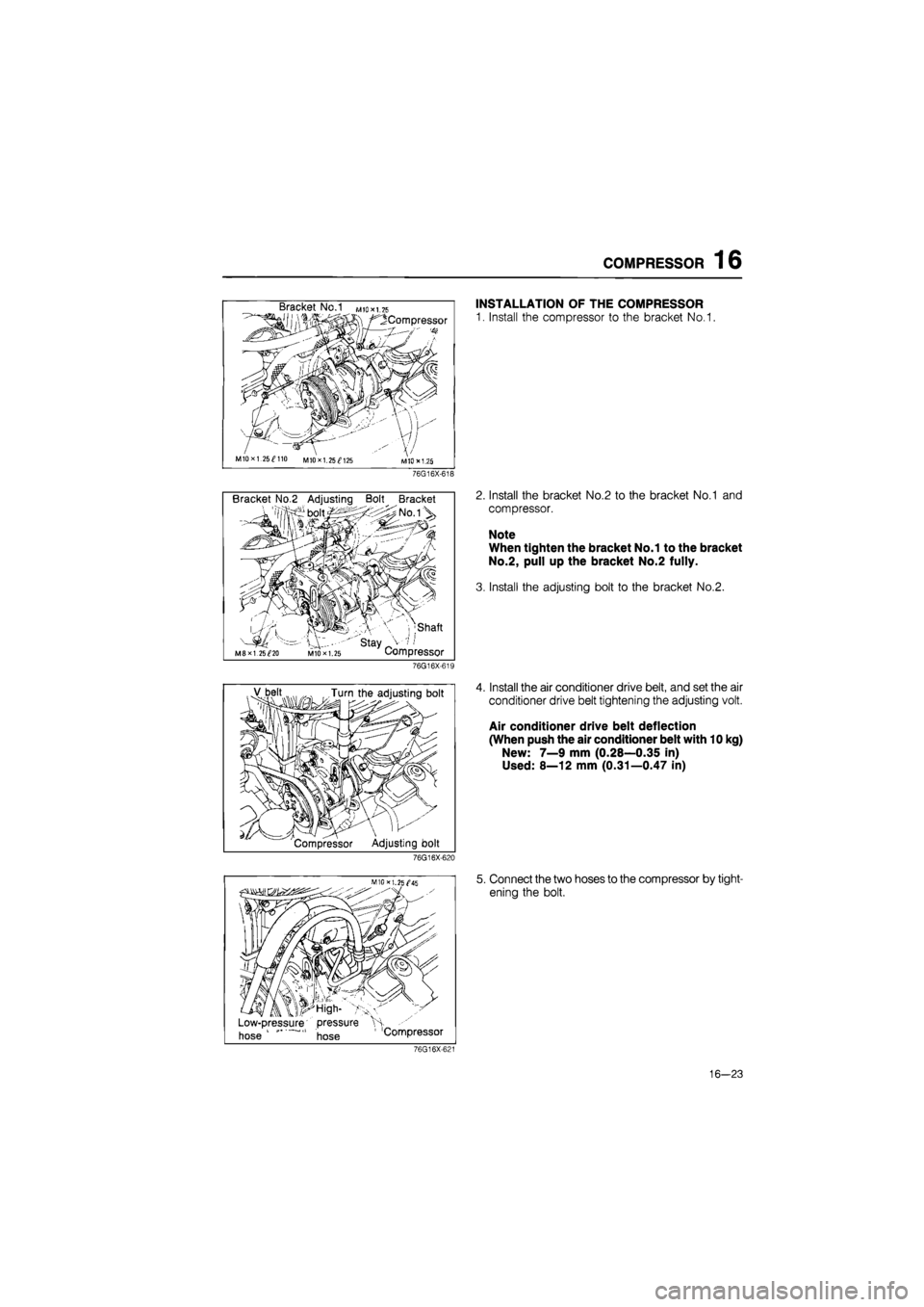
INSTALLATION OF THE COMPRESSOR
1. Install the compressor to the bracket No.1.
2. Install the bracket No.2 to the bracket No.1 and
compressor.
Note
When tighten the bracket No.1 to the bracket
No.2, pull up the bracket No.2 fully.
3. Install the adjusting bolt to the bracket No.2.
4. Install the air conditioner drive belt, and set the air
conditioner drive belt tightening the adjusting volt.
Air conditioner drive belt deflection
(When push the air conditioner belt with 10 kg)
New: 7—9 mm (0.28—0.35 in)
Used: 8—12 mm (0.31—0.47 in)
5. Connect the two hoses to the compressor by tight-
ening the bolt.
76G16X-621
16—23
Page 1816 of 1865
30 TECHNICAL DATA
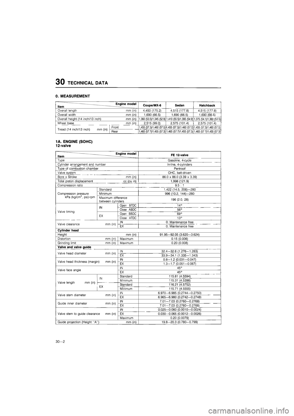
0. MEASUREMENT
Item Engine model Coupe/MX-6 Sedan Hatchback
Overall length mm (in) 4,450 (175.2) 4,515 (177.8) 4,515 (177.8)
Overall width mm (in) 1,690 (66.5) 1,690 (66.5) 1,690 (66.5)
Overall height (14 inch/13 inch) mm (in) 1,360 (53.5)/1,345 (52.9) 1,410 (55 5)/1,395 (54.9) 1,375 (54.1)/1,360 (53 5)
Wheel base mm (in) 2,515 (99.0) 2,575 (101.4) 2,575 (101.4)
Tread (14 inch/13 inch)
mm (in)
Front 1,455 (57.3)/1,460 (57.5) 1,455 (57.3)/(1,460 (57.5) 1,455 (57.3)/1,460 (57.5) Tread (14 inch/13 inch)
mm (in)
Rear 1,465 (57.7)/1,455 (57.3) 1,465 (57.7)/1,455 (57.3) 1,465 (57 7)/1,455 (57 3)
1
A. ENGINE (SOHC)
12-valve
— Engine model Item FE 12-valve
~vpe
Gasoline, 4-cycle
Cylinder arrangement and number In-line, 4-cylinders
Type
of
combustion chamber Pentroof
Valve system OHC, belt-driven
Bore
x
Stroke
mm (in)
86.0
x
86.0 (3.39
x
3.39)
Total piston displacement
cc
(cu
in)
1,998 (121.9)
Compression ratio 9.5
: 1
Compression pressure
kPa (kg/cm2, psi)-rpm
Standard 1,422 (14.5, 206)—280
Compression pressure
kPa (kg/cm2, psi)-rpm
Minimum 996 (10.2, 144)—280 Compression pressure
kPa (kg/cm2, psi)-rpm Maximum difference
between cylinders 196 (2.0,
28)
Valve timing
IN
Open
BTDC 14°
Valve timing
IN Close ABDC 56° Valve timing
EX Open BBDC 69° Valve timing
EX Close ATDC 13°
Valve clearance
mm (in)
IN 0; Maintenance free Valve clearance
mm (in)
EX 0; Maintenance free
Cylinder head
Heiaht
mm (inl
91.95-92.05 (3.620-3.624)
Distortion
mm (inl
Maximum 0.15 (0.006)
Grinding limit
mm (in)
Maximum 0.20 (0.008)
Valve and valve auide
Valve head diameter
mm (in)
IN 32.4-32.6 (1.276—1.283) Valve head diameter
mm (in)
EX 33.9-34.1 (1.335-1.343)
Valve head thickness (margin)
mm (in)
IN 0.8-1.2 (0.031—0.0471 Valve head thickness (margin)
mm (in)
EX 1.3—1.7 (0.051-0.067)
Valve face angle IN 45° Valve face angle EX 45°
Valve length
mm (in)
IN Standard 115.81 (4.55941
Valve length
mm (in)
IN Minimum 115.31 (4.5398) Valve length
mm (in)
cv Standard 116.21 (4.5752)
Minimum 115.71 (4.55551
Valve stem diameter
mm (in)
IN 6.970-6.985 (0.2744-0.2750) Valve stem diameter
mm (in)
EX 6.965-6.980 (0.2742-0.27481
Guide inner diameter
mm (in)
IN 7.01-7.03 (0,2760-0.2768) Guide inner diameter
mm (in)
EX 7.01-7.03 (0.2760-0.27681
Valve stem
to
guide clearance
mm (in)
IN 0.025-0.060 (0.0010-0.0024)
Valve stem
to
guide clearance
mm (in)
EX 0.030-0.065 (0.0012—0.0026) Valve stem
to
guide clearance
mm (in)
Maximum 0.20 (0.00791
Guide projection (Height "A")
mm (in)
19.8-20.3 (0.780-0.799)
30—2
Page 1819 of 1865
TECHNICAL DATA 30
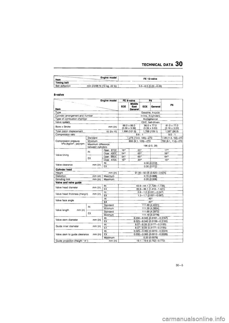
" Engine model Item FE 12-valve
Timing belt
Belt deflection
mm
(in)/98
N
(10 kg,
22 lb)
5.5—6.5 (0.22-0.26)
8-valve
Engine model
Item -••--.
FE 8-valve F8
F6
Engine model
Item -••--. ECE Middle
East
General
ECE General F6
Type Gasoline, 4-cycle
Cylinder arrangement and number In-line, 4-cylinders
Type
of
combustion chamber Multispherical
Valve system OHC, belt-driven
Bore
x
Stroke
mm
(in) 86.0
x
86.0 (3.39
x
3.39) 86.0
x
77.0
(3.39
x
3.03)
81.0
x
77.0 (3.19
x
3.03)
Total piston displacement
cc
(cu
in)
1,998 (121.9) 1,789 (109.1) 1,587 (96.8)
Compression ratio 8.6
: 1
9.0
: 1
Compression pressure kPa (kg/cm2, psi)-rpm
Standard 1,275 (13.0, 185)—270 1,128 (11.5, 164)—270
Compression pressure kPa (kg/cm2, psi)-rpm Minimum 893 (9.1, 129)—270 790 (8.1, 114)—270 Compression pressure kPa (kg/cm2, psi)-rpm Maximum difference
between cylinders 196 (2.0,
28)
Valve timing
IN Open BTDC 16° 20° 17°
Valve timing
IN Close ABDC 54° 65° 56° Valve timing
EX Open BBDC 54° 65° 64° Valve timing
EX Close ATDC 16° 20° 15°
Valve clearance
mm
(in) IN 0.30 (0.012) Valve clearance
mm
(in) EX 0.30 (0.012)
Cylinder head
Height
mm (in)
91.95-92.05 (3.620-3.624)
Distortion
mm
(in) Maximum 0.15 (0.006)
Grinding limit mm (in) Maximum 0.20 (0.008)
Valve and valve guide
Valve head diameter
mm
(in) IN 43.9-44.1 (1.728-1.736) Valve head diameter
mm
(in) EX 35.9-36.1 (1.413-1.421)
Valve head thickness (margin)
mm
(in) IN 0.8—1.2 (0.031-0.047) Valve head thickness (margin)
mm
(in) EX 1.3-1.7 (0.051-0.067)
Valve face angle IN 45° Valve face angle EX 45°
Valve length
mm
(in)
IN Standard 111.89 (4.4051)
Valve length
mm
(in)
IN Minimum 111.39 (4.3854) Valve length
mm
(in)
EX Standard 111.69 (4.3972) Valve length
mm
(in)
EX Minimum 111.19 (4.3776)
Valve stem diameter
mm
(in) IN 8.030-8.045 (0.3161-0.3167) Valve stem diameter
mm
(in) EX 8.025-8.040 (0.3159-0.3165)
Guide inner diameter
mm
(in) IN 8.07-8.09 (0.3177-0.3185) Guide inner diameter
mm
(in) EX 8.07-8.09 (0.3177-0.3185)
Valve stem
to
guide clearance
mm
(in)
IN 0.025-0.060 (0.0010-0.0024)
Valve stem
to
guide clearance
mm
(in) EX 0.030-0.065 (0.0012-0.0026) Valve stem
to
guide clearance
mm
(in)
Maximum 0.20 (0.0079)
Guide projection (Height "A")
mm
(in) 19.1-19.6 (0.752-0.772)
30-5
Page 1822 of 1865
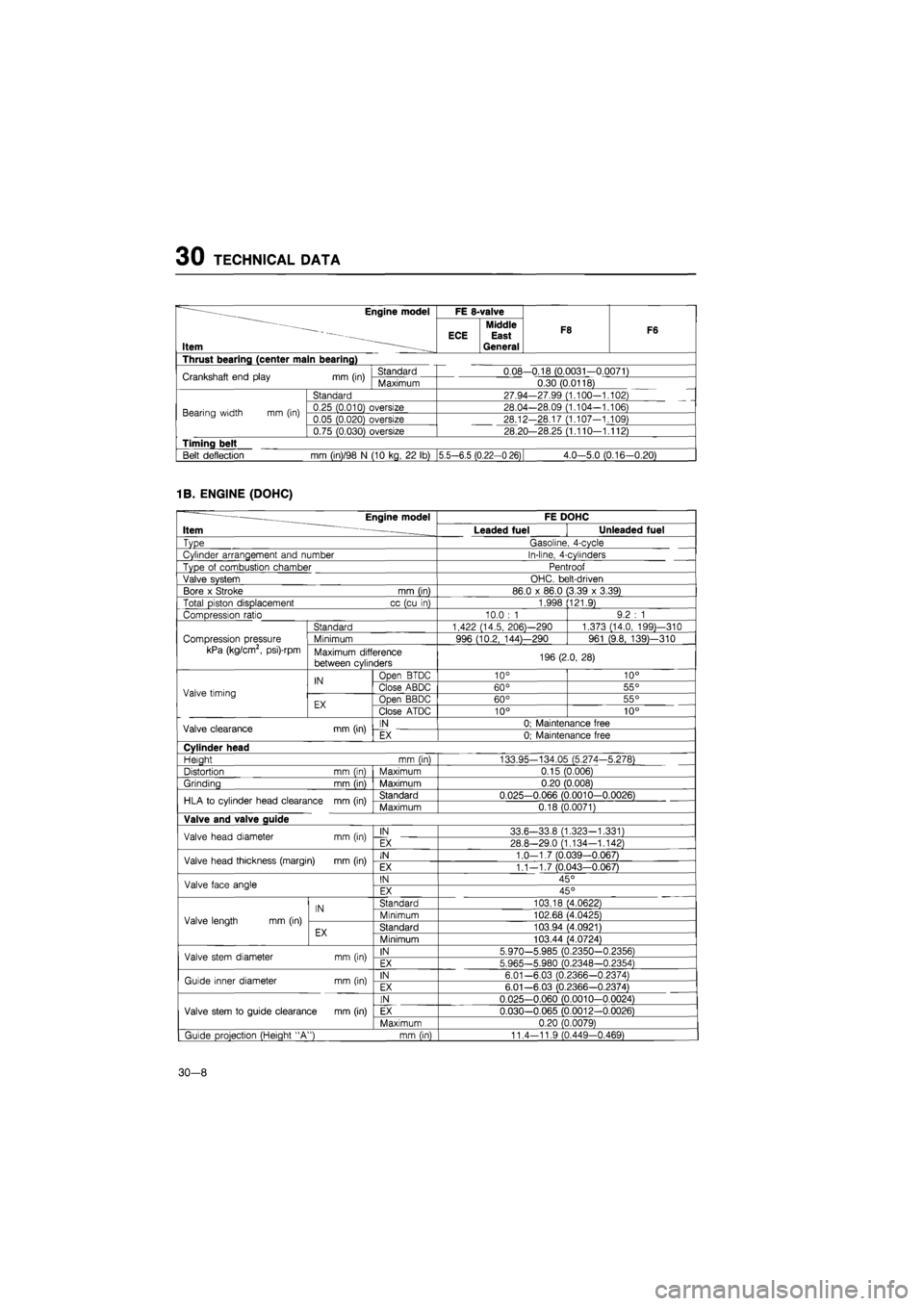
30 TECHNICAL DATA
~ ——Engine model
Item —
FE 8-valve
F8 F6
~ ——Engine model
Item —
Middle ECE East General
F8 F6
Thrust bearing (center main bearing)
Crankshaft end play
mm
(in) Standard 0.08-0.18 (0.0031-0.0071) Crankshaft end play
mm
(in) Maximum 0.30 (0.0118)
Bearing width
mm (in)
Standard 27.94-27.99 (1.100-1.102)
Bearing width
mm (in)
0.25 (0.010) oversize 28.04—28.09 (1.104-1.106) Bearing width
mm (in)
0.05 (0.020) oversize 28.12-28.17 (1.107-1.109) Bearing width
mm (in)
0.75 (0.030) oversize 28.20—28.25 (1.110—1.112)
Timing belt
Belt deflection
mm
(in)/98
N
(10 kg,
22 lb)
|5.5—6.5 (0.22-0 26) 4.0-5.0 (0.16-0.20)
1B. ENGINE (DOHC)
— Engine model FE DOHC
Item ~ Leaded fuel Unleaded fuel
Type Gasoline, 4-cycle
Cylinder arrangement and number In-line, 4-cylinders
Type
of
combustion chamber Pentroof
Valve system OHC. belt-driven
Bore
x
Stroke mm (in) 86.0
x
86.0 (3.39
x
3.39)
Total piston displacement cc (cu
in)
1,998 (121.9)
Compression ratio 10.0
: 1
9.2
: 1
Standard 1,422 (14.5, 206)—290 1,373 (14.0, 199)—310
Compression pressure Minimum 996 (10.2, 144)—290 961 (9.8, 139)—310
kPa (kg/cm2, psi)-rpm Maximum difference
between cylinders 196 (2.0, 28)
IN Open BTDC 10° 10°
Valve timing
IN Close ABDC 60° 55° Valve timing
EX Open BBDC 60° 55° EX Close ATDC 10° 10°
Valve clearance mm (in) IN 0; Maintenance free Valve clearance mm (in) EX 0; Maintenance free
Cylinder head
Heiaht mm (in) 133.95-134.05 (5.274-5.278)
Distortion mm (in) Maximum 0.15 (0.006)
Grinding mm (in) Maximum 0.20 (0.008)
HLA
to
cylinder head clearance mm (in) Standard 0.025-0.066 (0.0010-0.0026) HLA
to
cylinder head clearance mm (in) Maximum 0.18 (0.0071)
Valve and valve guide
Valve head diameter mm (in) IN 33.6-33.8 (1.323-1.331) Valve head diameter mm (in) EX 28.8-29.0 (1.134—1.142)
Valve head thickness (margin)
mm
(in) IN 1.0-1.7 (0.039-0.067) Valve head thickness (margin)
mm
(in) EX 1.1—1.7 (0.043—0.067)
Valve face angle IN 45° Valve face angle EX 45°
IN Standard 103.18 (4.0622)
Valve length
mm (in)
IN Minimum 102.68 (4.0425) Valve length
mm (in)
EX Standard 103.94 (4.0921) EX Minimum 103.44 (4.0724)
Valve stem diameter mm (in) IN 5.970-5.985 (0.2350-0.2356) Valve stem diameter mm (in) EX 5.965-5.980 (0.2348—0.2354)
Guide inner diameter mm (in) IN 6.01-6.03 (0.2366-0.2374) Guide inner diameter mm (in) EX 6.01—6.03 (0.2366-0.2374)
IN 0.025-0.060 (0.0010-0.0024)
Valve stem
to
guide clearance mm (in) EX 0.030-0.065 (0.0012-0.0026)
Maximum 0.20 (0.0079)
| Guide projection (Height "A") mm (in) 11.4-11.9 (0.449-0.469)
30-8
Page 1824 of 1865
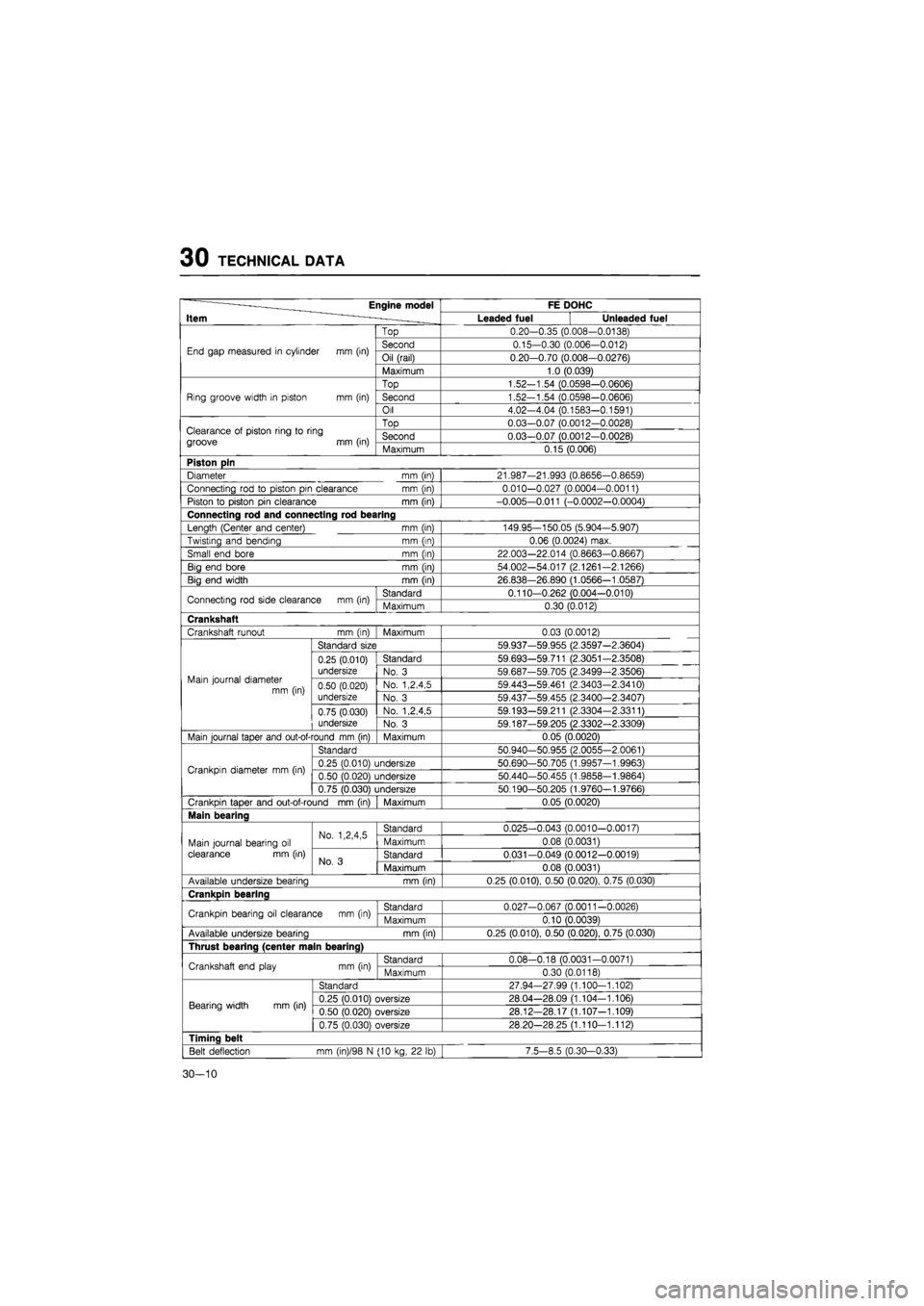
30 TECHNICAL DATA
~ ———Engine model
Item ~ . _
FE DOHC ~ ———Engine model
Item ~ . _ Leaded fuel Unleaded fuel
End gap measured
in
cylinder
mm
(in)
Top 0.20-0.35 (0.008-0.0138)
End gap measured
in
cylinder
mm
(in) Second 0.15-0.30 (0.006-0.012) End gap measured
in
cylinder
mm
(in) Oil (rail) 0.20-0.70 (0.008-0.0276) End gap measured
in
cylinder
mm
(in)
Maximum 1.0 (0.039)
Ring groove width
in
piston
mm (in)
Top 1.52-1.54 (0.0598—0.0606)
Ring groove width
in
piston
mm (in)
Second 1.52-1.54 (0.0598-0.0606) Ring groove width
in
piston
mm (in)
Oil 4.02-4.04 (0.1583—0.1591)
Clearance
of
piston ring
to
ring
groove
mm
(in)
Top 0.03-0.07 (0.0012-0.0028) Clearance
of
piston ring
to
ring
groove
mm
(in) Second 0.03-0.07 (0.0012-0.0028) Clearance
of
piston ring
to
ring
groove
mm
(in) Maximum 0.15 (0.006)
Piston pin
Diameter
mm (in)
21.987-21.993 (0.8656-0.8659)
Connecting rod
to
piston pin clearance
mm (in)
0.010-0.027 (0.0004-0.0011)
Piston
to
piston pin clearance
mm
(in) -0.005-0.011 (-0.0002-0.0004)
Connecting rod and connecting rod bearing
Length (Center and center)
mm (in)
149.95—150.05 (5.904-5.907)
Twisting and bending
mm
(in) 0.06 (0.0024) max.
Small end bore
mm (in)
22.003-22.014 (0.8663-0.8667)
Big end bore
mm (in)
54.002-54.017 (2.1261-2.1266)
Big end width
mm
(in) 26.838-26.890 (1.0566-1.0587)
Connecting rod side clearance
mm
(in) Standard 0.110-0.262 (0.004-0.010) Connecting rod side clearance
mm
(in) Maximum 0.30 (0.012)
Crankshaft
Crankshaft runout
mm (in)
Maximum 0.03 (0.0012)
Main journal diameter mm (in)
Standard size 59.937-59.955 (2.3597-2.3604)
Main journal diameter mm (in)
0.25 (0.010)
undersize
Standard 59.693—59.711 (2.3051-2.3508)
Main journal diameter mm (in)
0.25 (0.010)
undersize No.
3
59.687-59.705 (2.3499-2.35061 Main journal diameter mm (in) 0.50 (0.020)
undersize
No. 1,2,4,5 59.443-59.461 (2.3403-2.3410) Main journal diameter mm (in) 0.50 (0.020)
undersize No.
3
59.437-59.455 (2.3400-2.3407)
Main journal diameter mm (in)
0.75 (0.030)
undersize
No. 1,2,4,5 59.193-59.211 (2.3304-2.3311)
Main journal diameter mm (in)
0.75 (0.030)
undersize No.
3
59.187-59.205 (2.3302-2.3309)
Main journal taper and out-of-round mm (in) Maximum 0.05 (0.0020)
Crankpin diameter
mm
(in)
Standard 50.940-50.955 (2.0055-2.0061)
Crankpin diameter
mm
(in) 0.25 (0.010) undersize 50.690-50.705 (1.9957-1.9963) Crankpin diameter
mm
(in) 0.50 (0.020) undersize 50.440-50.455 (1.9858-1.9864) Crankpin diameter
mm
(in)
0.75 (0.030) undersize 50.190-50.205 (1.9760-1.9766)
Crankpin taper and out-of-round
mm
(in) Maximum 0.05 (0.0020)
Main bearing
Main journal bearing
oil
clearance
mm
(in)
No. 1,2,4,5 Standard 0.025-0.043 (0.0010-0.0017)
Main journal bearing
oil
clearance
mm
(in)
No. 1,2,4,5 Maximum 0.08 (0.0031) Main journal bearing
oil
clearance
mm
(in) No.
3
Standard 0.031-0.049 (0.0012-0.0019)
Main journal bearing
oil
clearance
mm
(in) No.
3
Maximum 0.08 (0.0031)
Available undersize bearing
mm
(in) 0.25 (0.010), 0.50 (0.020), 0.75 (0.030)
Crankpin bearing
Crankpin bearing
oil
clearance
mm
(in) Standard 0.027-0.067 (0.0011-0.0026) Crankpin bearing
oil
clearance
mm
(in) Maximum 0.10 (0.0039)
Available undersize bearina
mm
(in) 0.25 (0.010), 0.50 (0.020), 0.75 (0.030)
Thrust bearing (center main bearing)
Crankshaft end play
mm
(in) Standard 0.08-0.18 (0.0031-0.0071) Crankshaft end play
mm
(in) Maximum 0.30 (0.0118)
Bearing width
mm
(in)
Standard 27.94-27.99 (1.100-1.102)
Bearing width
mm
(in) 0.25 (0.010) oversize 28.04—28.09 (1.104-1.106) Bearing width
mm
(in) 0.50 (0.020) oversize 28.12—28.17 (1.107-1.109) Bearing width
mm
(in)
0.75 (0.030) oversize 28.20-28.25 (1.110-1.112)
Timing belt
Belt deflection
mm
(in)/98
N
(10 kg,
22 lb)
7.5-8.5 (0.30-0.33)
30—10
Page 1825 of 1865
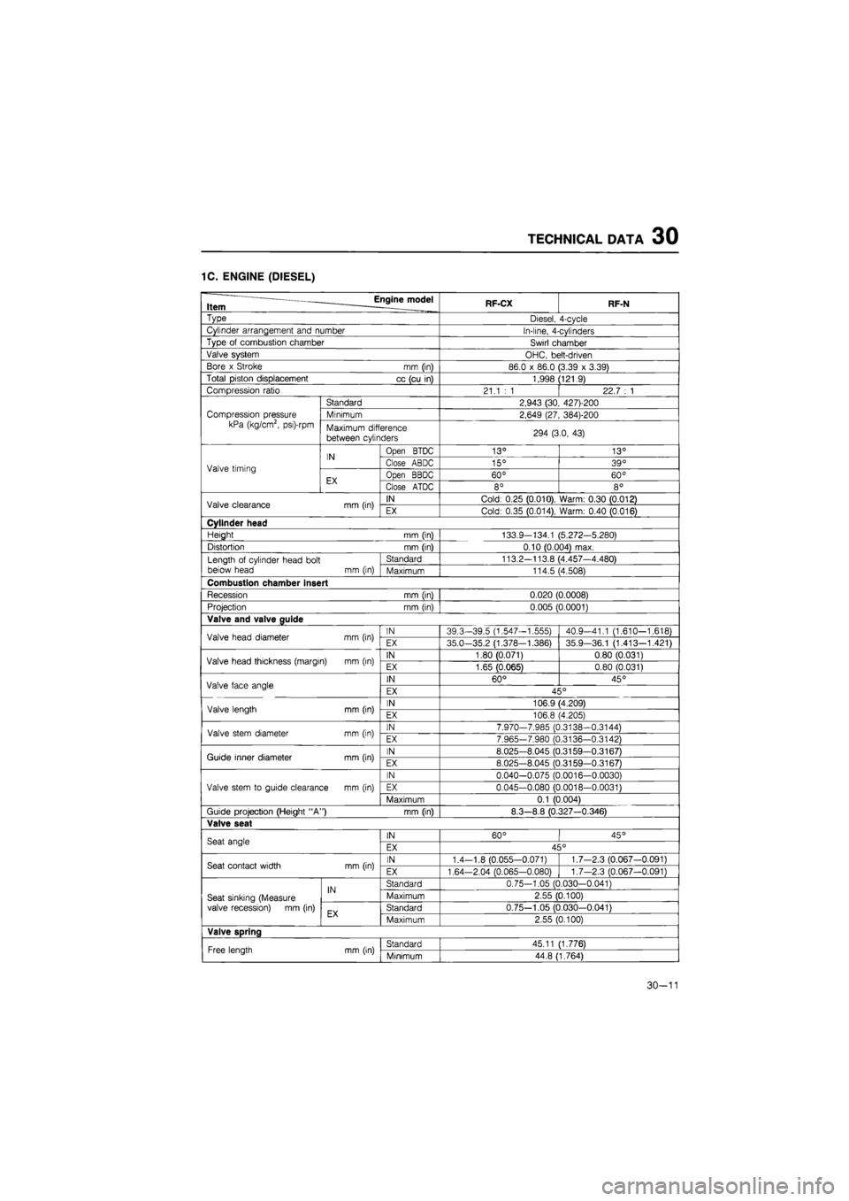
TECHNICAL DATA 30
1C. ENGINE (DIESEL)
— _____ Engine model Item . RF-CX RF-N
Type Diesel, 4-cycle
Cylinder arrangement and number In-line, 4-cylinders
Type
of
combustion chamber Swirl chamber
Valve system OHC, belt-driven
Bore
x
Stroke
mm (in)
86.0
x
86.0 (3.39
x
3.39)
Total piston displacement
cc
(cu
in)
1,998 (121.9)
Compression ratio 21.1
: 1 |
22.7
: 1
Compression pressure
kPa (kg/cm2, psi)-rpm
Standard 2,943 (30, 427)-200
Compression pressure
kPa (kg/cm2, psi)-rpm Minimum 2,649 (27, 384)-200 Compression pressure
kPa (kg/cm2, psi)-rpm Maximum difference
between cylinders 294 (3.0,
43)
Valve timing
IN Open BTDC 13° 13°
Valve timing
IN Close ABDC 15° 39° Valve timing
EX Open BBDC 60° 60° Valve timing
EX Close ATDC 8° 8°
Valve clearance
mm
(in) IN Cold: 0.25 (0.010), Warm: 0.30 (0.012) Valve clearance
mm
(in) EX Cold: 0.35 (0.014), Warm: 0.40 (0.016)
Cylinder head
Height mm (in) 133.9-134.1 (5.272-5.280)
Distortion mm (in) 0.10 (0.004) max.
Length
of
cylinder head bolt beiow head
mm
(in)
Standard 113.2—113.8 (4.457—4.480) Length
of
cylinder head bolt beiow head
mm
(in) Maximum 114.5 (4.508)
Combustion chamber insert
Recession
mm
(in) 0.020 (0.0008)
Projection
mm
(in) 0.005 (0.0001)
Valve and valve guide
Valve head diameter
mm
(in) IN 39.3-39.5 (1.547—1.555) 40.9-41.1 (1.610—1.618) Valve head diameter
mm
(in) EX 35.0-35.2 (1.378-1.386) 35.9-36.1 (1.413—1.421)
Valve head thickness (margin)
mm
(in) IN 1.80 (0.071) 0.80 (0.031) Valve head thickness (margin)
mm
(in) EX 1.65 (0.065) 0.80 (0.031)
Valve face angle IN 60° 45° Valve face angle EX 45°
Valve length mm (in) IN 106.9(4.209) Valve length mm (in) EX 106.8 (4.205)
Valve stem diameter
mm
(in) IN 7.970-7.985 (0.3138—0.3144) Valve stem diameter
mm
(in) EX 7.965-7.980 (0.3136-0.3142)
Guide inner diameter mm (in) IN 8.025-8.045 (0.3159—0.3167) Guide inner diameter mm (in) EX 8.025-8.045 (0.3159—0.3167)
Valve stem
to
guide clearance
mm (in)
IN 0.040-0.075 (0.0016-0.0030)
Valve stem
to
guide clearance
mm (in)
EX 0.045—0.080 (0.0018-0.0031) Valve stem
to
guide clearance
mm (in)
Maximum 0.1 (0.004)
Guide projection (Height "A")
mm
(in) 8.3-8.8 (0.327-0.346)
Valve seat
Seat angle IN 60° 45° Seat angle EX 45°
Seat contact width
mm
(in) IN 1.4-1.8 (0.055—0.071) 1.7-2.3 (0.067-0.091) Seat contact width
mm
(in) EX 1.64-2.04 (0.065-0.080) 1.7-2.3 (0.067-0.091)
Seat sinking (Measure valve recession)
mm
(in)
IN Standard 0.75-1.05 (0.030-0.041)
Seat sinking (Measure valve recession)
mm
(in)
IN Maximum 2.55 (0.100) Seat sinking (Measure valve recession)
mm
(in) EX Standard 0.75—1.05 (0.030-0.041) Seat sinking (Measure valve recession)
mm
(in) EX Maximum 2.55 (0.100)
Valve spring
Free length
mm
(in) Standard 45.11 (1.776) Free length
mm
(in) Minimum 44.8 (1.764)
30-11
Page 1827 of 1865
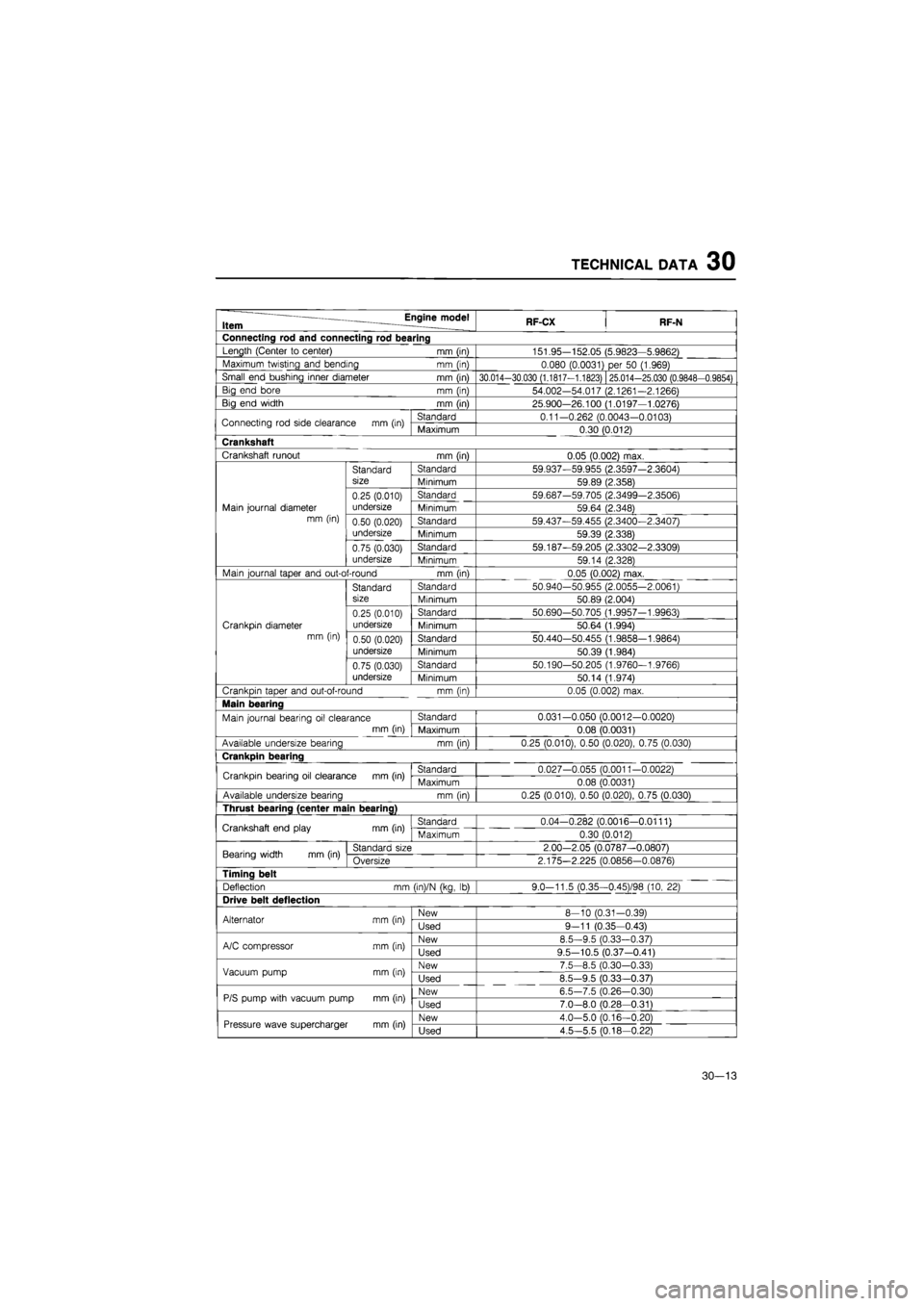
TECHNICAL DATA 30
Item Engine model RF-CX RF-N
Connecting rod and connecting rod bearing
Length (Center
to
center) mm (in) 151.95-152.05 (5.9823—5.9862)
Maximum twisting and bending mm (in) 0.080 (0.0031)
per 50
(1.969)
Small end bushing inner diameter mm (in) 30.014-30.030 (1.1817-1.1823) 25.014-25.030 (0.9848-0.9854)
Big end bore mm (in) 54.002-54.017 (2.1261-2.1266)
Big end width mm (in) 25.900—26.100 (1.0197—1.0276)
Connecting rod side clearance mm (in) Standard 0.11-0.262 (0.0043-0.0103) Connecting rod side clearance mm (in) Maximum 0.30 (0.012)
Crankshaft
Crankshaft runout mm (in) 0.05 (0.002) max.
Standard Standard 59.937-59.955 (2.3597-2.3604)
size Minimum 59.89 (2.358)
0.25 (0.010) Standard 59.687-59.705 (2.3499-2.3506)
Main journal diameter undersize Minimum 59.64 (2.348) mm (in) 0.50 (0.020) Standard 59.437-59.455 (2.3400-2.3407)
undersize Minimum 59.39 (2.338)
0.75 (0.030) Standard 59.187-59.205 (2.3302-2.3309)
undersize Minimum 59.14 (2.328)
Main journal taper and out-of-round mm (in) 0.05 (0.002) max.
Standard Standard 50.940-50.955 (2.0055—2.0061)
size Minimum 50.89 (2.004)
0.25 (0.010) Standard 50.690-50.705 (1.9957-1.9963)
Crankpin diameter undersize Minimum 50.64 (1.994) mm (in) 0.50 (0.020) Standard 50.440-50.455 (1.9858—1.9864)
undersize Minimum 50.39 (1.984)
0.75 (0.030) Standard 50.190-50.205 (1.9760-1.9766)
undersize Minimum 50.14 (1.974)
Crankpin taper and out-of-round mm (in) 0.05 (0.002) max.
Main bearing
Main journal bearing
oil
clearance Standard 0.031-0.050 (0.0012-0.0020)
mm (in) Maximum 0.08 (0.0031)
Available undersize bearina mm fin) 0.25 (0.010), 0.50 (0.020), 0.75 (0.030)
Crankpin bearing
Crankpin bearing
oil
clearance mm (in) Standard 0.027-0.055 (0.0011-0.0022) Crankpin bearing
oil
clearance mm (in) Maximum 0.08 (0.0031)
Available undersize bearing mm (in) 0.25 (0.010), 0.50 (0.020), 0.75 (0.030)
Thrust bearina (center main bearina)
Crankshaft end play mm (in) Standard 0.04-0.282 (0.0016—0.0111) Crankshaft end play mm (in) Maximum 0.30 (0.012)
Bearing width mm (in) Standard size 2.00-2.05 (0.0787-0.0807) Bearing width mm (in) Oversize 2.175-2.225 (0.0856-0.0876)
Timing belt
Deflection mm (in)/N (ka,
lb)
9.0-11.5 (0.35--0.45V98 (10,
22)
Drive belt deflection
Alternator mm (in) New 8-10 (0.31-0.39) Alternator mm (in) Used 9-11 (0.35-0.43)
A/C compressor mm (in) New 8.5-9.5 (0.33-0.37) A/C compressor mm (in) Used 9.5-10.5 (0.37-0.41)
Vacuum pump mm (in) New 7.5-8.5 (0.30—0.33) Vacuum pump mm (in) Used 8.5-9.5 (0.33-0.37)
P/S pump with vacuum pump mm (in) New 6.5-7.5 (0.26—0.30) P/S pump with vacuum pump mm (in) Used 7.0-8.0 (0.28—0.31)
Pressure wave supercharger
mm
(in) New 4.0-5.0 (0.16-0.20) Pressure wave supercharger
mm
(in) Used 4.5-5.5 (0.18-0.22)
30—13