Page 1139 of 1865
ON-VEHICLE MAINTENANCE 7C
ON-VEHICLE MAINTENANCE
AUTOMATIC TRANSAXLE FLUID (ATF)
Inspection for Fluid Leaks
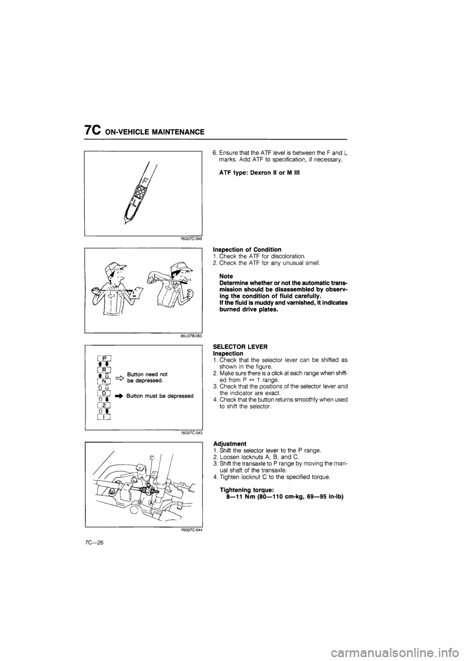
Check for fluid leaks; the following figure shows the locations where fluid leakage may possibly occur.
1. Kick-down solenoid
2. Vacuum diaphragm
3. Manual shaft
4. Speedometer driven gear
5. Oil level tube
6. Governor cover
7. Governor
8. Oil pan
9. Oil pump
10. Inhibitor switch
11. Transaxle case
12. Oil pump
13. Square head plugs
14. Bearing cover
15. Drive shaft
76G07C-041
©
i
©
[JdQ©
I
Inspection of Level
1. Apply the parking brake and block the wheels to
prevent the vehicle from rolling.
Note
Place the car on a flat, level surface.
2. Run the engine so that the automatic transaxle fluid
reaches operating temperature.
3. While the engine is idling, shift the select lever from
P to 1 and back again.
4. Let the engine idle.
5.Shift the select lever to P.
76G07C-042
7C-25
Page 1140 of 1865

7C ON-VEHICLE MAINTENANCE
76G07C-349
[ff/A rm \ I
86U07B-065
« I
•D
cS
o 0
m 0 «
o «
. Button need not
^ be depressed.
Button must be depressed
76G07C-043
6. Ensure that the ATF level is between the F and L
marks. Add ATF to specification, if necessary.
ATF type: Dexron II or M II!
Inspection of Condition
1. Check the ATF for discoloration.
2. Check the ATF for any unusual smell.
Note
Determine whether or not the automatic trans-
mission should be disassembled by observ-
ing the condition of fluid carefully.
If the fluid is muddy and varnished, it indicates
burned drive plates.
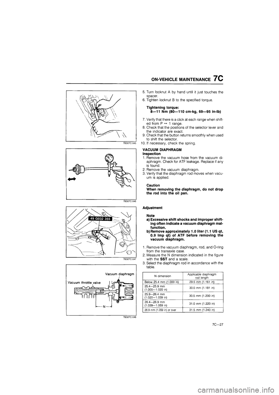
SELECTOR LEVER
Inspection
1. Check that the selector lever can be shifted as
shown in the figure.
2. Make sure there is a click at each range when shift-
ed from P <-• 1 range.
3. Check that the positions of the selector lever and
the indicator are exact.
4. Check that the button returns smoothly when used
to shift the selector.
Adjustment
1. Shift the selector lever to the P range.
2. Loosen locknuts A, B, and C.
3. Shift the transaxle to P range by moving the man-
ual shaft of the transaxle.
4. Tighten locknut C to the specified torque.
Tightening torque:
8—11 N-m (80—110 cm-kg, 69—95 in-lb)
76G07C-044
7C-26
Page 1141 of 1865

ON-VEHICLE MAINTENANCE 7C
76G07C-045
fflfiirv T
5. Turn locknut A by hand until it just touches the
spacer.
6. Tighten locknut B to the specified torque.
Tightening torque:
8—11 N-m (80—110 cm-kg, 69—95 in-lb)
7. Verify that there is a click at each range when shift-
ed from P «-» 1 range.
8. Check that the positions of the selector lever and
the indicator are exact.
9. Check that the button returns smoothly when used
to shift the selector.
10. If necessary, check the spring.
VACUUM DIAPHRAGM
Inspection
1. Remove the vacuum hose from the vacuum di-
aphragm. Check for ATF leakage. Replace if any
is found.
2. Remove the vacuum diaphragm.
3. Verify that the diaphragm rod moves when vacu-
um is applied.
Caution
When removing the diaphragm, do not drop
the rod into the oil pan.
76G07C-046
Vacuum diaphragm
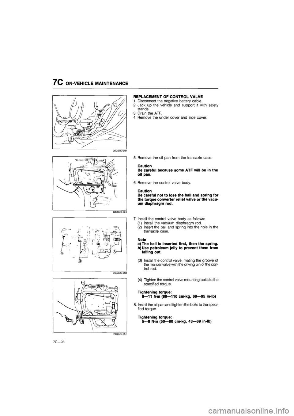
Adjustment
Note
a) Excessive shift shocks and improper shift-
ing often indicate a vacuum diaphragm mal-
function.
b) Remove approximately 1.0 liter (1.1 US qt,
0.9 Imp qt) of ATF before removing the
vacuum diaphragm.
1. Remove the vacuum diaphragm, rod, and O-ring
from the transaxle case.
2. Measure the N dimension indicated in the figure
with the SST and a scale.
3. Select the diaphragm rod in accordance with the
table.
N dimension Applicable diaphragm
rod length
Below 25.4 mm (1.000 in) 29.5 mm (1.161 in)
25.4—25.9 mm (1.000-1.020 in) 30.0 mm (1.181 in)
25.9—26.4 mm (1.020-1.039 in) 30.5 mm (1.200 in)
26.4—26.9 mm
(1.039—1.059 in) 31.0 mm (1.220 in)
26.9 mm (1.059 in) or over 31.5 mm (1.240 in)
76G07C-048
10,-21
Page 1142 of 1865

7C ON-VEHICLE MAINTENANCE
REPLACEMENT OF CONTROL VALVE
1. Disconnect the negative battery cable.
2. Jack up the vehicle and support it with safety
stands.
3. Drain the ATF.
4. Remove the under cover and side cover.
76G07C-049
63U07B-024
jr
j riSJS
®
76G07C-050
5. Remove the oil pan from the transaxle case.
Caution
Be careful because some ATF will be in the
oil pan.
6. Remove the control valve body.
Caution
Be careful not to lose the ball and spring for
the torque converter relief valve or the vacu-
um diaphragm rod.
7. Install the control valve body as follows:
(1) Install the vacuum diaphragm rod.
(2) Insert the ball and spring into the hole in the
transaxle case.
Note
a) The ball is inserted first, then the spring.
b) Use petroleum jelly to prevent them from
falling out.
(3) Install the control valve, mating the groove of
the manual valve with the driving pin of the con-
trol rod.
(4) Tighten the control valve mounting bolts to the
specified torque.
Tightening torque:
8—11 N-m (80—110 cm-kg, 69—95 in-lb)
8. Install the oil pan and tighten the bolts to the speci-
fied torque.
Tightening torque:
5—8 N-m (50—80 cm-kg, 43—69 in-lb)
76G07C-051
7C-28
Page 1144 of 1865
7C REMOVAL
REMOVAL
PREPARATION
(1) Drain the ATF before removal.
(2) Attach the engine support.
(3) Jack up the vehicle and support it with safety stands.
Components
1. Battery
2. Battery carrier
3. Fresh air duct
4. Main fuse block
5. Distributor leads
6. Speedometer cable
7. Cnnectors
8. Ground wires
9. Selector cable
10. Vacuum hose
11. Front wheels
12. Splash shields
13. Oil cooler outlet and inlet
hoses
14. Tie-rod ends
15. Stabilizer bar control links
16. Lower arm ball joints
17. Driveshaft
18. Joint shaft bracket
76G07C-056
19. Joint shaft and driveshaft
20. Under cover
21. Torque converter bolts
22. Starter
23. Engine mount No.4
24. Engine mount No.2
25. Crossmember and left side
lower arm
26. Transaxle
7C-30
Page 1145 of 1865
REMOVAL 7C
76G07C-057
76G07C-058
76G07C-059
1. Remove the battery and battery carrier.
2. Remove the fresh air duct.
3. Disconnect the main fuse block.
4. Disconnect the distributor leads.
5. Disconnect the speedometer cable.
6. Disconnect the connectors.
(1) Inhibitor switch
(2) Kick-down solenoid
7. Disconnect the grounds from the transaxle case
and oil pump.
8. Disconnect the selector cable.
9. Disconnect the vacuum hose.
10. Remove the front wheels.
11. Remove the splash shields.
12. Drain the ATF.
13. Disconnect the oil cooler outlet and inlet hoses.
76G07C-060
7C—31
Page 1146 of 1865
7C REMOVAL
14. Disconnect the tie-rod ends with the SST.
76G07C-061
76G07C-062
76G07C-063
15. Remove the stabilizer bar control links.
16. Remove the bolts and nuts at the left and right low-
er arm ball joints.
17. Pull the lower arms downward to separate them
from the knuckles.
Caution
Do not damage the ball joint dust boots.
18. Separate the left driveshaft from the transaxle by
prying with a bar inserted between the shaft and
the case.
Caution
Do not damage the oil seal.
19. Remove the joint shaft bracket.
20. Separate the right driveshaft together with the joint
shaft in the same manner.
21. Install the SST into the differential side gears.
Caution
Failure to install the SST may allow the
differential side gears to become misaligned.
76G07C-064
7C—32
Page 1148 of 1865
7C REMOVAL
27. Remove engine mount No. 2.
76G07C-069
76G07C-070
28. Remove the crossmember and the left side lower
arm as an assembly.
29. Lean the engine toward the transaxle by loosen-
ing the engine support hook bolt.
30. Support the transaxle with a jack.
31. Remove the transaxle mounting bolts.
32. Remove the transaxle.
76G07C-071
7C-34