Page 1082 of 1865
7B INSTALLATION
1. Attach rope at 2 places on the transaxle. Place a
flat board on a jack and set the transaxle on it.
Caution
The transaxle is not well balanced; be care-
ful when positioning it on the jack.
2. Move the transaxle into place and attach the rope
to the SST.
86U07B-441
3. Mount the transaxle to the engine.
Tightening torque:
89—117
N m
(9.1—11.9 m-kg, 66—86 ft-lb)
Note
a) Lift the transaxle with the jack while pull-
ing the rope.
b) Align the torque converter bolts and drive
plate holes.
86U07B-442
4. Install engine mount No. 4 and bracket.
Tightening torque:
Bolt
36—54 Nm (3.7—5.5 m-kg, 27—40 ft-lb)
Nut
64—89
N
m (6.5—9.1 m-kg, 47—66 ft-lb)
86U07B-443
5. Install engine mount No. 2.
Tightening torque:
(A)
85—117
N
m
(8.7—11.9 m-kg, 63—86 ft-lb)
(|)67—93 Nm
(6.8—9.5 m-kg, 49—69 ft-lb)
86U07B-444
7B—216
Page 1084 of 1865

7B INSTALLATION
86U07B-449
Standard bolt Reamer bolt
86U07B-450
86U07B-451
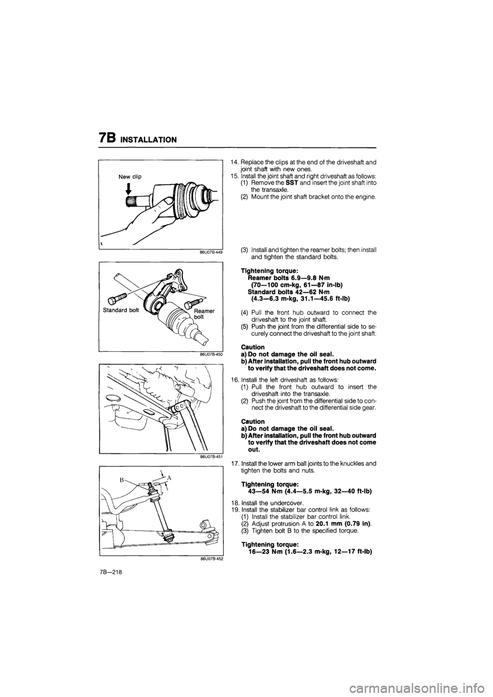
14. Replace the clips at the end of the driveshaft and
joint shaft with new ones.
15. Install the joint shaft and right driveshaft as follows:
(1) Remove the SST and insert the joint shaft into
the transaxle.
(2) Mount the joint shaft bracket onto the engine.
(3) Install and tighten the reamer bolts; then install
and tighten the standard bolts.
Tightening torque:
Reamer bolts 6.9—9.8 N-m
(70—100 cm-kg, 61—87 in-lb)
Standard bolts 42—62 N-m
(4.3—6.3 m-kg, 31.1—45.6 ft-lb)
(4) Pull the front hub outward to connect the
driveshaft to the joint shaft.
(5) Push the joint from the differential side to se-
curely connect the driveshaft to the joint shaft.
Caution
a) Do not damage the oil seal.
b) After installation, pull the front hub outward
to verify that the driveshaft does not come.
16. Install the left driveshaft as follows:
(1) Pull the front hub outward to insert the
driveshaft into the transaxle.
(2) Push the joint from the differential side to con-
nect the driveshaft to the differential side gear.
Caution
a) Do not damage the oil seal.
b) After installation, pull the front hub outward
to verify that the driveshaft does not come
out.
17. Install the lower arm ball joints to the knuckles and
tighten the bolts and nuts.
Tightening torque:
43—54 N-m (4.4—5.5 m-kg, 32—40 ft-lb)
18. Install the undercover.
19. Install the stabilizer bar control link as follows:
(1) Install the stabilizer bar control link.
(2) Adjust protrusion A to 20.1 mm (0.79 in).
(3) Tighten bolt B to the specified torque.
Tightening torque:
16—23 N-m (1.6—2.3 m-kg, 12—17 ft-lb)
86U07B-452
7B-218
Page 1085 of 1865
INSTALLATION 7B
86U07B-453
86U07B-454
76G07B-198
20. Install the tie-rod ends and cotter pins.
Tightening torque:
29—44 N-m (3.0—4.5 m-kg, 22—33 ft-lb)
21. Install the oil cooler outlet and inlet hoses.
22. Install the splash shields.
Tightening torque:
8—11 N-m (80—110 cm-kg, 69—95 in-lb)
23. Install the front wheels.
Tightening torque:
88—118 N-m (9—12 m-kg, 65—87 ft-lb)
24. Connect the throttle cable.
Note
Adjust the throttle cable with the oil pressure
test. (Refer to page 7B—75, 76)
25. Connect the selector cable.
Tightening torque:
Nut
29—39 N-m (3.0—4.0 m-kg, 22—29 ft-lb)
Bolts
16—22 N-m (1.6—2.3 m-kg, 12—17 ft-lb)
26. Connect the ground wires to the transaxle case.
Tightening torque:
8—11 N-m (80—115 cm-kg, 69—99 in-lb)
86U07B-456
7B—219
Page 1086 of 1865

7B INSTALLATION
27. Connect the connectors as follows:
(1) Inhibitor switch
(2) Solenoid valve
(3) Pulse generator (G4A-EL)
(4) Fluid temperature switch (G4A-EL)
28. Connect the speedometer cable.
76G07B-199
76G07B-200
76G07B-201
29. Install the fresh air duct. (G4A-HL)
30. Install the air cleaner hose. (G4A-EL)
31. Install the air cleaner assembly; then connect the
air flow meter connector and inlet hose. (G4A-EL)
Tightening torque:
Bolt
31—40 N-m (3.2—4.1 m-kg, 23—30 in-lb)
Nut
8—11 N-m (80—110 cm-kg, 69—95 in-lb)
32. Connect the distributor lead.
33. Install the main fuse block.
Tightening torque:
8—11 N-m (80—110 cm-kg, 69—95 in-lb)
34. Install the battery carrier and battery.
Tightening torque:
31—40 N-m (3.2—4.1 m-kg, 23—30 in-lb)
35. Pour in ATF and check the following:
(1) With the engine idling, check that the fluid lev-
el is between the F and L marks on the dip-
stick. (Refer to page 7B—71)
(2) Check the manual linkage, and adjust if neces-
sary. (Refer to page 7B—72)
(3) Check the inhibitor switch operation. (Refer to
page 7B—65)
(4) Conduct a road test. (Refer to page 7B—34,
35)
(5) Check that there is no fluid leakage from the
transaxle. (Refer to page 7B—71)
76G07B-202
7B—220
Page 1115 of 1865

7C
AUTOMATIC TRANSAXLE
(3-Speed)
OUTLINE 7C— 2
SPECIFICATIONS 7C— 2
CROSS-SECTIONAL VIEW 7C— 3
OPERATION OF COMPONENTS . 7C— 4
FLUID PASSAGE LOCATION 7C— 5
TROUBLESHOOTING 7C— 8
GENERAL NOTE 7C— 8
QUICK DIAGNOSIS CHART 7C— 9
STEP 1
(PRELIMINARY INSPECTION).... 7C— 12
STEP 2 (STALL TEST) 7C— 14
STEP 3 (TIME LAG TEST) 7C— 17
STEP 4 (ROAD TEST) 7C— 18
STEP 5 (OIL PRESSURE TEST)... 7C— 20
ELECTRIC COMPONENTS 7C— 23
INHIBITOR SWITCH 7C— 23
KICK-DOWN SWITCH 7C— 23
KICK-DOWN SOLENOID 7C— 24
ON-VEHICLE MAINTENANCE 7C- 25
AUTOMATIC TRANSAXLE FLUID
(ATF) 7C— 25
SELECTOR LEVER 7C— 26
VACUUM DIAPHRAGM 7C— 27
REPLACEMENT OF CONTROL
VALVE 7C— 28
REPLACEMENT OF SERVO
PISTON RETURN SPRING 7C— 29
REMOVAL 7C— 30
PREPARATION 7C— 30
DISASSEMBLY 7C— 35
DISASSEMBLY-STEP 1 7C— 35
DISASSEMBLY-STEP 2 7C— 41
DISASSEMBLY-STEP 3 7C— 45
DISASSEMBLY-STEP 4 7C— 51
INSPECTION AND REPAIR 7C- 54
PRECAUTION 7C— 54
TORQUE CONVERTER 7C— 54
OIL PUMP 7C— 55
FRONT CLUTCH 7C— 58
REAR CLUTCH 7C— 62
REAR CLUTCH HUB 7C— 65
DRUM HUB 7C— 66
ONE-WAY CLUTCH INNER RACE 7C— 68
BAND SERVO 7C— 69
BRAKE BAND 7C— 70
PLANETARY CARRIER (FRONT).. 7C— 71
ONE-WAY CLUTCH 7C— 71
LOW AND REVERSE BRAKE 7C— 71
GOVERNOR 7C— 72
CONTROL VALVE BODY 7C— 75
DIFFERENTIAL 7C— 79
OUTPUT GEAR 7C— 82
IDLE GEAR 7C— 83
BEARING COVER ASSEMBLY .... 7C— 86
BEARING HOUSING 7C— 87
SIDE BEARING HOUSING 7C— 88
ASSEMBLY 7C— 89
PRECAUTION 7C— 89
ASSEMBLY-STEP 1 7C— 89
ASSEMBLY-STEP 2 7C— 98
ASSEMBLY-STEP 3 7C—106
ASSEMBLY-STEP 4 7C—111
INSTALLATION 7C—119
TORQUE SPECIFICATIONS 7C—119
HYDRAULIC CIRCUIT 7C—125
OUTLINE 7C—125
P RANGE 7C—126
R RANGE 7C—127
N RANGE 7C—128
D RANGE (1ST GEAR) 7C—129
D RANGE (2ND GEAR) 7C—130
D RANGE (3RD GEAR) 7C—131
D RANGE (KICK-DOWN; SHIFT
VALVES IN 2ND POSITION) 7C—132
2 RANGE (2ND GEAR) 7C—133
1 RANGE (1ST GEAR) 7C—134
1 RANGE (2ND GEAR) 7C—135
76G07C-001
Page 1116 of 1865
7C OUTLINE
OUTLINE
SPECIFICATIONS
Model F3A Model FE engine F6 engine
Torque converter stall torque ratio 1.800-2.100 : 1
Gear ratio
First 2.841
Gear ratio Second 1.541 Gear ratio
Third 1.000
Gear ratio
Reverse 2.400
Final gear ratio 3.450 : 1 3.631 : 1
Number of drive plates/ driven plates
Front clutch 3/3
Number of drive plates/ driven plates Rear clutch 4/4 Number of drive plates/ driven plates
Low and reverse brake 4/4
Servo diameter (Piston outer dia./retainer inner dia.) mm (in) 64/36 (2.52/1.42) 64/44 (2.52/1.73)
Speedometer gear ratio (Driven/Drive gear) 0.80 (20/25) 0.84 (21/25)
Automatic transaxle fluid
Type Dexron-II or M-III
Automatic transaxle fluid Capacity liters
(US qt, Imp qt) 6.2 (6.6, 5.5)
76G07C-002
7C—2
Page 1117 of 1865
OUTLINE 7C
CROSS-SECTIONAL VIEW
76G07C-003
1. Transaxle case
2. Front clutch
3. Rear clutch
4. Connecting shell
5. Rear clutch hub
6. Planetary carrier (front)
7. Sun gear
8. Low and reverse brake
9. One-way clutch
10. One-way clutch inner race
11. Planetary carrier (rear)
12. Drum hub assembly
13. Bearing housing
14. Output gear
15. Turbine shaft
16. Oil pump shaft
17. Bearing cover
18. Oil seal
19. Torque converter
20. Converter housing
21. Oil seal
22. Speedometer drive gear
63U07B-003
23. Side gear
24. Pinion gear
25. Pinion shaft
26. Differential gear case
27. Ring gear
28. Oil seal
29. Side bearing housing
30. Control valve body
31. Oil pan
32. Oil pump
7C-3
Page 1120 of 1865
7C OUTLINE
Transaxle Case
Outlet to governor valve
Inlet to governor valve'
Governor pressure
check port
To low and reverse brake
Band servo (Apply side)
Band servo (Release side)
Inlet to governor valve Inlet to oil pump
Outlet to front clutch
Outlet to rear clutch
Outlet to governor valve j Outlet to torque converter
Line pressure check port Outlet to oil pump
Outlet to oil pump Inlet to oil pump
Outlet to front clutch
Outlet to rear clutch
Outlet to torque converter
Band servo (Apply side)
Band servo (Release side)
Outlet to governor valve—
Inlet to governor valve
reverse brake
76G07C-008
7C—6