Page 1150 of 1865
7C DISASSEMBLY
Procedure
Precaution
(1) Clean the transaxle exterior thoroughly with steam and/or cleaning solvents prior to disassembly.
(2) Disassemble the transaxle in a clean area (dustproof workspace) to prevent dust entry into the
mechanisms.
(3) Inspect the individual transaxle components in accordance with the QUICK DIAGNOSIS CHART
during disassembly.
(4) Use plastic hammers when applying force to separate the light alloy case joints.
(5) Do not use rags during disassembly to prevent contamination.
(6) Neatly arrange the removed parts in order during disassembly.
76G07C-073
1. Remove the torque converter from the converter
housing.
Note
Do not allow the ATF to spill when removing
the torque converter.
83U07B-119
2. Pull out the oil pump shaft by hand.
3. Remove the turbine shaft.
76G07C-074
h
ii ii = J
4. Remove the clip from the turbine shaft.
Note
Do not reuse the clip.
76G07C-075
7C-36
Page 1151 of 1865
DISASSEMBLY 7C
5. Assembly the SST.
76G07C-076
76G07C-350
6. Attach the hanger to the oil pump as shown.
7. Lift the transaxle and mount it on the SST.
Warning
Avoid leaning the transaxle to one side dur-
ing disassembly, it may turn quickly and cause
injury.
Note
If troubleshooting indicates that there is a
problem on the differential side, separate the
transaxle case assembly from the converter
housing and cover it.
63U07B-064
8. Remove the inhibitor switch.
76G07C-077
7C—37
Page 1154 of 1865
7C DISASSEMBLY
17. Remove the oil pump.
Note
If the oil pump is difficult to remove, remove
it after tightening the anchor-end bolt to se-
cure the front clutch with the brake band.
76G07C-084
18. Measure the total end play.
Standard clearance:
a) Straight edge—Pump cover
Maximum 0.10 mm (0.004 in)
b) Straight edge—Transaxle case
Maximum 0.15 mm (0.006 in)
Note
If it is not within specification, use the bear-
ing outer race to make the adjustment at the
time of installation. (Refer to page 7C—112.)
76G07C-085
7C-40
Page 1155 of 1865
DISASSEMBLY 7C
DISASSEMBLY - STEP 2 76G07C-086
76G07C-087
1. Anchor-end bolt and
locknut
2. Brake band
3. Strut
4. Front clutch
5. Rear clutch
6. Rear clutch hub assembly
7. Planetary carrier (front)
8. Seal sleeve
9. Sun gear and spacer
10. Connecting shell
11. Servo
12. Transaxle case
13. Governor
7C—41
Page 1158 of 1865
7C DISASSEMBLY
76G07C-096
76G07C-097
76G07C-098
10. Remove the servo.
(1) Compress the servo retainer with the SST.
(2) Remove the snap ring.
(3) Remove the servo retainer and return spring
from the transaxle case while loosing the SST.
11. Remove the bolts, and remove the transaxle case
by tapping lightly with a plastic hammer.
12. Remove the governor assembly.
(1) Remove the governor cover and gasket.
(2) Remove the governor assembly and gasket.
76G07C-099
7C—44
Page 1164 of 1865
7C DISASSEMBLY
12. Remove the control rod.
(1) Remove the pin, and remove the control rod
from the transaxle.
Warning
Be careful when removing the control rod, the
detent ball will be pushed out by spring force.
(2) Remove the detent ball and spring.
76G07C-119
7C-50
Page 1166 of 1865
7C DISASSEMBLY
76G07C-122
76G07C-123
76G07C-124
Procedure
1. Remove the side bearing housing installation bolts
from the transaxle case.
2. Remove the side bearing housing from the trans-
axle case by tapping lightly with a plastic hammer.
3. Remove the differential assembly.
4. Remove the bearing housing.
(1) Remove the bolt indicated in the figure (arrow).
(2) Remove the roll pin with a pin punch.
(3) Remove the bearing housing by tapping light-
ly with a plastic hammer.
76G07C-125
7C-52
Page 1185 of 1865

INSPECTION AND REPAIR 7C
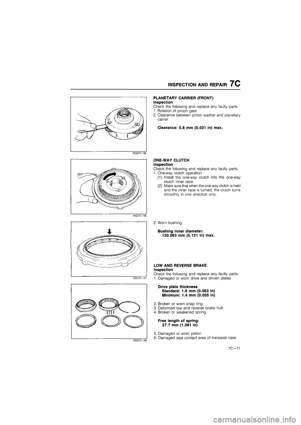
76G07C-185
76G07C-186
76G07C-187
PLANETARY CARRIER (FRONT)
Inspection
Check the following and replace any faulty parts.
1. Rotation of pinion gear
2. Clearance between pinion washer and planetary
carrier
Clearance: 0.8 mm (0.031 in) max.
ONE-WAY CLUTCH
Inspection
Check the following and replace any faulty parts.
1. One-way clutch operation
(1) Install the one-way clutch into the one-way
clutch inner race.
(2) Make sure that when the one-way clutch is held
and the inner race is turned, the clutch turns
smoothly in one direction only.
2. Worn bushing
Bushing inner diameter:
130.063 mm (5.121 in) max.
76G07C-188
LOW AND REVERSE BRAKE
Inspection
Check the following and replace any faulty parts.
1. Damaged or worn drive and driven plates
Drive plate thickness
Standard: 1.6 mm (0.063 in)
Minimum: 1.4 mm (0.055 in)
2. Broken or worn snap ring
3. Deformed low and reverse brake hub
4. Broken or weakened spring
Free length of spring:
27.7 mm (1.091 in)
5. Damaged or worn piston
6. Damaged seal contact area of transaxle case
7C-71