Page 527 of 878

OIL AND FILTER REPLACEMENT
CAUTION:
wProlonged and repeated contact with mineral oil will re-
sult in the removal of natural fats from the skin, leading
to dryness, irritation and dermatitis. In addition, used en-
gine oil contains potentially harmful contaminants which
may cause skin cancer.
wExercise caution in order to minimize the length and fre-
quency of contact of your skin to used oil. Wear protec-
tive clothing and gloves. Wash your skin thoroughly with
soap and water, or use waterless hand cleaner, to remove
any used engine oil. Do not use gasoline, thinners, or sol-
vents.
wIn order to preserve the environment, used oil and used
oil filters must be disposed of only at designated dispos-
al sites.
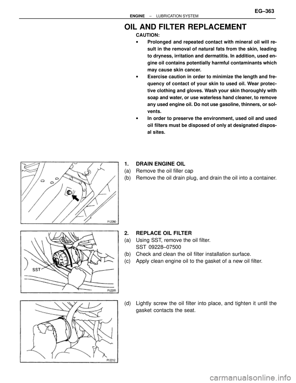
1. DRAIN ENGINE OIL
(a) Remove the oil filler cap
(b) Remove the oil drain plug, and drain the oil into a container.
2. REPLACE OIL FILTER
(a) Using SST, remove the oil filter.
SST 09228±07500
(b) Check and clean the oil filter installation surface.
(c) Apply clean engine oil to the gasket of a new oil filter.
(d) Lightly screw the oil filter into place, and tighten it until the
gasket contacts the seat.
± ENGINELUBRICATION SYSTEMEG±363
Page 528 of 878

(e) Using SST, tighten it an additional 3/4 turn.
SST 09228±07500
3. REFILL WITH ENGINE OIL
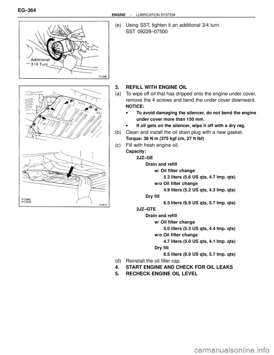
(a) To wipe off oil that has dripped onto the engine under cover,
remove the 4 screws and bend the under cover downward.
NOTICE:
wTo avoid damaging the silencer, do not bend the engine
under cover more than 150 mm.
wIf oil gets on the silencer, wipe it off with a dry rag.
(b) Clean and install the oil drain plug with a new gasket.
Torque: 38 NVm (375 kgfVcm, 27 ftVlbf)
(c) Fill with fresh engine oil.
Capacity:
2JZ±GE
Drain and refill
w/ Oil filter change
5.3 liters (5.6 US qts, 4.7 Imp. qts)
w/o Oil filter change
4.9 liters (5.2 US qts, 4.3 Imp. qts)
Dry fill
6.5 liters (6.9 US qts, 5.7 Imp. qts)
2JZ±GTE
Drain and refill
w/ Oil filter change
5.0 liters (5.3 US qts, 4.4 Imp. qts)
w/o Oil filter change
4.7 liters (5.0 US qts, 4.1 Imp. qts)
Dry fill
6.5 liters (6.9 US qts, 5.7 Imp. qts)
(d) Reinstall the oil filler cap.
4. START ENGINE AND CHECK FOR OIL LEAKS
5. RECHECK ENGINE OIL LEVEL EG±364
± ENGINELUBRICATION SYSTEM
Page 535 of 878
INSTALLATION HINT:
Use a new gasket (2JZ±GE) or O±ring (2JZ±GTE).
Torque:
2JZ±GE
49 NVm (500 kgfVcm, 36 ftVlbf)
2JZ±GTE
29 NVm (300 kgfVcm, 22 ftVlbf)
2. REMOVE DRIVE AND DRIVEN ROTORS
Remove the 10 screws, pump body cover, the drive and driv-
en rotors.
Torque: 10 NVm (105 kgfVcm, 8.0 ftVlbf)
ASSEMBLY HINT: Place the drive and driven rotors into the
oil pump body with the mark facing upward.
OIL PUMP INSPECTION
1. INSPECT RELIEF VALVE
Coat the valve with engine oil and check that it falls smoothly
into the valve hole under its own weight.
If it doesn't, replace the relief valve. If necessary, replace the
oil pump assembly.
2. INSPECT DRIVE AND DRIVEN ROTORS
A. Place drive and driven rotors into oil pump body
ASSEMBLY HINT: Place the drive and driven rotors into the
oil pump body with the mark facing upward.
± ENGINELUBRICATION SYSTEMEG±371
Page 542 of 878

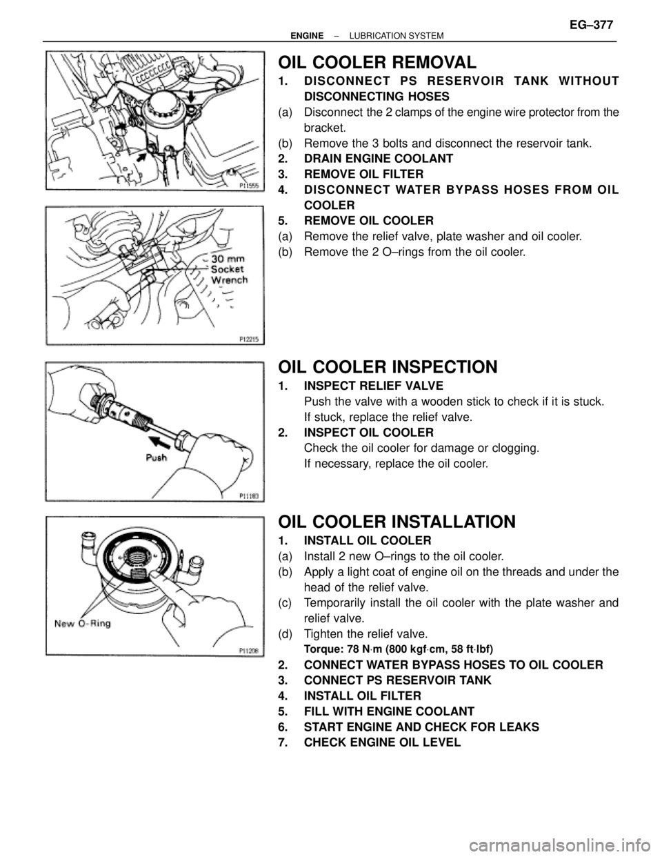
OIL COOLER REMOVAL
1. DISCONNECT PS RESERVOIR TANK WITHOUT
DISCONNECTING HOSES
(a) Disconnect the 2 clamps of the engine wire protector from the
bracket.
(b) Remove the 3 bolts and disconnect the reservoir tank.
2. DRAIN ENGINE COOLANT
3. REMOVE OIL FILTER
4. DISCONNECT WATER BYPASS HOSES FROM OIL
COOLER
5. REMOVE OIL COOLER
(a) Remove the relief valve, plate washer and oil cooler.
(b) Remove the 2 O±rings from the oil cooler.
OIL COOLER INSPECTION
1. INSPECT RELIEF VALVE
Push the valve with a wooden stick to check if it is stuck.
If stuck, replace the relief valve.
2. INSPECT OIL COOLER
Check the oil cooler for damage or clogging.
If necessary, replace the oil cooler.
OIL COOLER INSTALLATION
1. INSTALL OIL COOLER
(a) Install 2 new O±rings to the oil cooler.
(b) Apply a light coat of engine oil on the threads and under the
head of the relief valve.
(c) Temporarily install the oil cooler with the plate washer and
relief valve.
(d) Tighten the relief valve.
Torque: 78 NVm (800 kgfVcm, 58 ftVlbf)
2. CONNECT WATER BYPASS HOSES TO OIL COOLER
3. CONNECT PS RESERVOIR TANK
4. INSTALL OIL FILTER
5. FILL WITH ENGINE COOLANT
6. START ENGINE AND CHECK FOR LEAKS
7. CHECK ENGINE OIL LEVEL
± ENGINELUBRICATION SYSTEMEG±377
Page 543 of 878
OIL NOZZLE (2JZ±GTE)
COMPONENTS
OIL NOZZLES REMOVAL
1. REMOVE CRANKSHAFT
(See step 6 in cylinder block disassembly in Engine Me-
chanical)
2. REMOVE OIL NOZZLES (WITH RELIEF VALVES)
Using a 5 mm hexagon wrench, remove the bolt and oil
nozzle. Remove the 6 oil nozzles.
OIL NOZZLES INSPECTION
INSPECT RELIEF VALVES (OIL NOZZLES)
Push the valve with a wooden stick to check if it is stuck.
If stuck, replace the relief valve.
OIL NOZZLES INSTALLATION
1. INSTALL OIL NOZZLES (WITH RELIEF VALVES)
Using a 5 mm hexagon wrench, install the oil nozzle with the
bolt. Install the 6 oil nozzles.
Torque: 8.8 NVm (90 kgfVcm, 78 in.Vlbf)
2. INSTALL CRANKSHAFT
(See step 8 in cylinder block assembly in Engine Me-
chanical) EG±378
± ENGINELUBRICATION SYSTEM
Page 549 of 878
POSITIVE CRANKCASE VENTILATION
(PCV) SYSTEM
PCV VALVE INSPECTION
1. REMOVE PCV VALVE
(a) Disconnect the PCV hose from the PCV valve.
(b) Remove the PCV valve.
2. INSTALL CLEAN HOSE TO PCV VALVE
3. INSPECT PCV VALVE OPERATION
(a) Blow air into the cylinder head side, and check that air passes
through easily.
CAUTION: Do not suck air through the valve. Petroleum sub-
stances inside the valve are harmful.
(b) Blow air into the air intake chamber side, and check that air
passes through with difficulty.
If operation is not as specified, replace the PCV valve.
4. REMOVE CLEAN HOSE FROM PCV VALVE
5. REINSTALL PCV VALVE
PCV HOSES AND CONNECTORS
INSPECTION
VISUALLY INSPECT HOSES, CONNECTIONS AND GAS-
KETS
Check for cracks, leaks or damage.
± ENGINEEMISSION CONTROL SYSTEMS (2JZ±GTE)EG±177
Page 550 of 878
EVAPORATIVE EMISSION (EVAP)
CONTROL SYSTEM
FUEL VAPOR LINES, FUEL TANK AND
TANK CAP INSPECTION
1. VISUALLY INSPECT LINES AND CONNECTIONS
Look for loose connections, sharp bends or damage.
2. VISUALLY INSPECT FUEL TANK
Look for deformation, cracks or fuel leakage.
3. VISUALLY INSPECT FUEL TANK CAP
Check if the cap and/or gasket are deformed or damaged.
If necessary, repair or replace the cap.
CHARCOAL CANISTER INSPECTION
1. REMOVE CHARCOAL CANISTER
2. VISUALLY INSPECT CHARCOAL CANISTER
Look for cracks or damage.
3. CHECK FOR CLOGGED FILTER AND STUCK CHECK
VA LV E
(a) Using low pressure compressed air (4.71 kPa (0.048
kgf/cm
2, 0.68 psi)), blow into port C and check that air flows
without resistance from the other ports. EG±178
± ENGINEEMISSION CONTROL SYSTEMS (2JZ±GTE)
Page 551 of 878

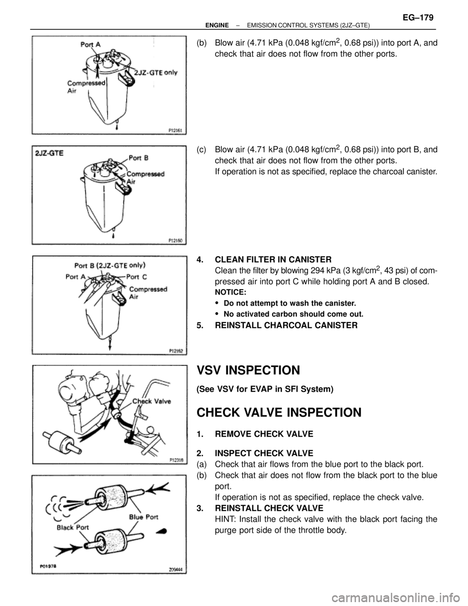
(b) Blow air (4.71 kPa (0.048 kgf/cm2, 0.68 psi)) into port A, and
check that air does not flow from the other ports.
(c) Blow air (4.71 kPa (0.048 kgf/cm
2, 0.68 psi)) into port B, and
check that air does not flow from the other ports.
If operation is not as specified, replace the charcoal canister.
4. CLEAN FILTER IN CANISTER
Clean the filter by blowing 294 kPa (3 kgf/cm
2, 43 psi) of com-
pressed air into port C while holding port A and B closed.
NOTICE:
� Do not attempt to wash the canister.
� No activated carbon should come out.
5. REINSTALL CHARCOAL CANISTER
VSV INSPECTION
(See VSV for EVAP in SFI System)
CHECK VALVE INSPECTION
1. REMOVE CHECK VALVE
2. INSPECT CHECK VALVE
(a) Check that air flows from the blue port to the black port.
(b) Check that air does not flow from the black port to the blue
port.
If operation is not as specified, replace the check valve.
3. REINSTALL CHECK VALVE
HINT: Install the check valve with the black port facing the
purge port side of the throttle body.
± ENGINEEMISSION CONTROL SYSTEMS (2JZ±GTE)EG±179