Page 566 of 878

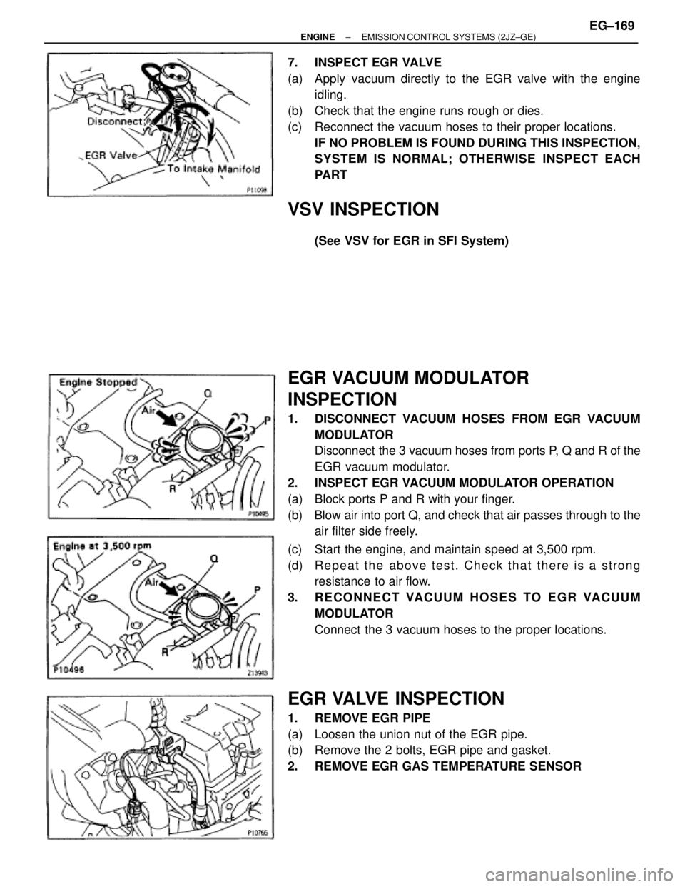
7. INSPECT EGR VALVE
(a) Apply vacuum directly to the EGR valve with the engine
idling.
(b) Check that the engine runs rough or dies.
(c) Reconnect the vacuum hoses to their proper locations.
IF NO PROBLEM IS FOUND DURING THIS INSPECTION,
SYSTEM IS NORMAL; OTHERWISE INSPECT EACH
PART
VSV INSPECTION
(See VSV for EGR in SFI System)
EGR VACUUM MODULATOR
INSPECTION
1. DISCONNECT VACUUM HOSES FROM EGR VACUUM
MODULATOR
Disconnect the 3 vacuum hoses from ports P, Q and R of the
EGR vacuum modulator.
2. INSPECT EGR VACUUM MODULATOR OPERATION
(a) Block ports P and R with your finger.
(b) Blow air into port Q, and check that air passes through to the
air filter side freely.
(c) Start the engine, and maintain speed at 3,500 rpm.
(d) Repeat the above test. Check that there is a strong
resistance to air flow.
3. RECONNECT VACUUM HOSES TO EGR VACUUM
MODULATOR
Connect the 3 vacuum hoses to the proper locations.
EGR VALVE INSPECTION
1. REMOVE EGR PIPE
(a) Loosen the union nut of the EGR pipe.
(b) Remove the 2 bolts, EGR pipe and gasket.
2. REMOVE EGR GAS TEMPERATURE SENSOR
± ENGINEEMISSION CONTROL SYSTEMS (2JZ±GE)EG±169
Page 567 of 878
3. REMOVE EGR VALVE
(a) Disconnect these hoses from the EGR valve:
(1) Vacuum hose
(2) Pressure hose
(b) Remove the 2 nuts, EGR valve and gasket.
4. INSPECT EGR VALVE
Check for sticking and heavy carbon deposits.
If a problem is found, replace the EGR valve.
5. REINSTALL EGR VALVE
(a) Place a new gasket on the intake air connector.
(b) Install the EGR valve with the 2 nuts.
Torque: 27 NVm (280 kgfVcm, 20 ftVlbf)
(c) Reconnect the following hoses to the EGR valve:
wVacuum hose
wPressure hose
6. REINSTALL EGR GAS TEMPERATURE SENSOR
Torque: 20 NVm (200 kgfVcm, 14 ftVlbf)
7. REINSTALL EGR PIPE
(a) Temporarily install the union nut of the EGR pipe.
(b) Install a new gasket and the EGR pipe with the 2 bolts.
Torque: 21 NVm (210 kgfVcm, 15 ftVlbf)
(c) Tighten the union nut of the EGR pipe.
Torque: 64 NVm (650 kgfVcm, 47 ftVlbf)
EG±170± ENGINEEMISSION CONTROL SYSTEMS (2JZ±GE)
Page 568 of 878
THREE±WAY CATALYTIC CONVERTER
(TWC) SYSTEM
EXHAUST PIPE ASSEMBLY INSPECTION
1. CHECK CONNECTIONS FOR LOOSENSESS OR
DAMAGE
2. CHECK CLAMPS FOR WEAKNESS, CRACKS OR
DAMAGE
TWC INSPECTION
CHECK FOR DENTS OR DAMAGE
If any part of the protector is damaged or dented to the extent
that it contacts the TWC, repair or replace it.
HEAT INSULATOR INSPECTION
1. CHECK HEAT INSULATOR FOR DAMAGE
2. CHECK FOR ADEQUATE CLEARANCE BETWEEN
CATALYTIC CONVERTER AND HEAT INSULATOR
± ENGINEEMISSION CONTROL SYSTEMS (2JZ±GE)EG±171
Page 573 of 878
COOLANT CHECK
1. CHECK ENGINE COOLANT LEVEL AT RADIATOR
RESERVOIR
The engine coolant level should be between the ºLOWº and
ºFULLº lines.
If low, check for leaks and add engine coolant up to the
ºFULLº line.
2. CHECK ENGINE COOLANT QUALITY
(a) Remove the radiator cap.
CAUTION: To avoid the danger of being burned, do not remove
the radiator cap while the engine and radiator are still hot, as
fluid and steam can be blown out under pressure.
(b) There should not be any excessive deposits of rust or scale
around the radiator cap or radiator filler hole, and the coolant
should be free from oil.
If excessively dirty, replace the coolant.
(c) Reinstall the radiator cap. EG±330
± ENGINECOOLING SYSTEM
Page 574 of 878

COOLANT REPLACEMENT
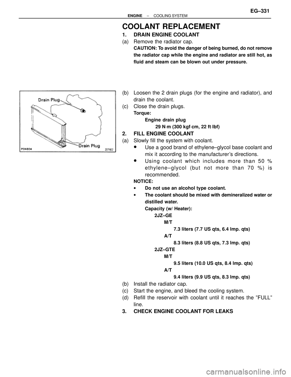
1. DRAIN ENGINE COOLANT
(a) Remove the radiator cap.
CAUTION: To avoid the danger of being burned, do not remove
the radiator cap while the engine and radiator are still hot, as
fluid and steam can be blown out under pressure.
(b) Loosen the 2 drain plugs (for the engine and radiator), and
drain the coolant.
(c) Close the drain plugs.
Torque:
Engine drain plug
29 NVm (300 kgfVcm, 22 ftVlbf)
2. FILL ENGINE COOLANT
(a) Slowly fill the system with coolant.
wUse a good brand of ethylene±glycol base coolant and
mix it according to the manufacturer's directions.
wUsing coolant which includes more than 50 %
ethylene±glycol (but not more than 70 %) is
recommended.
NOTICE:
wDo not use an alcohol type coolant.
wThe coolant should be mixed with demineralized water or
distilled water.
Capacity (w/ Heater):
2JZ±GE
M/T
7.3 liters (7.7 US qts, 6.4 lmp. qts)
A/T
8.3 liters (8.8 US qts, 7.3 lmp. qts)
2JZ±GTE
M/T
9.5 liters (10.0 US qts, 8.4 lmp. qts)
A/T
9.4 liters (9.9 US qts, 8.3 lmp. qts)
(b) Install the radiator cap.
(c) Start the engine, and bleed the cooling system.
(d) Refill the reservoir with coolant until it reaches the ºFULLº
line.
3. CHECK ENGINE COOLANT FOR LEAKS
± ENGINECOOLING SYSTEMEG±331
Page 579 of 878
(d) Remove the 2 nuts, and disconnect the No.2 water bypass
pipe from the water pump.
(e) 2JZ±GTE:
Disconnect the No.3 turbo water hose from the water pump.
(f) Remove the 6 bolts, water pump and gasket.
(g) Remove the O±ring from the cylinder block.
WATER PUMP COMPONENTS
INSPECTION
1. INSPECT WATER PUMP
Turn the pulley seat, and check that the water pump bearing
is not rough or noisy.
If necessary, replace the water pump.
2. INSPECT FLUID COUPLING
(a) Remove the 4 nuts and fan from the fluid coupling. EG±336
± ENGINECOOLING SYSTEM
Page 580 of 878

(b) Check that the fluid coupling is not damaged and that no
silicon oil leaks.
If necessary, replace the fluid coupling.
(c) Reinstall the fan to the fluid coupling with the 4 nuts.
Torque: 7.4 NVm (75 kgfVcm, 65 in.Vlbf)
WATER PUMP INSTALLATION
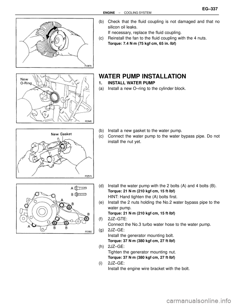
1. INSTALL WATER PUMP
(a) Install a new O±ring to the cylinder block.
(b) Install a new gasket to the water pump.
(c) Connect the water pump to the water bypass pipe. Do not
install the nut yet.
(d) Install the water pump with the 2 bolts (A) and 4 bolts (B).
Torque: 21 NVm (210 kgfVcm, 15 ftVlbf)
HINT: Hand tighten the (A) bolts first.
(e) Install the 2 nuts holding the No.2 water bypass pipe to the
water pump.
Torque: 21 NVm (210 kgfVcm, 15 ftVlbf)
(f) 2JZ±GTE:
Connect the No.3 turbo water hose to the water pump.
(g) 2JZ±GE:
Install the generator mounting bolt.
Torque: 37 NVm (380 kgfVcm, 27 ftVlbf)
(h) 2JZ±GE:
Tighten the generator mounting nut.
Torque: 37 NVm (380 kgfVcm, 27 ftVlbf)
(i) 2JZ±GE:
Install the engine wire bracket with the bolt.
± ENGINECOOLING SYSTEMEG±337
Page 582 of 878
11. 2JZ±GTE M/T:
INSTALL DRIVE BELT TENSIONER DAMPER
12. INSTALL RADIATOR ASSEMBLY
(See radiator installation)
13. 2JZ±GE:
INSTALL AIR CLEANER, VAF METER AND INTAKE AIR
CONNECTOR PIPE ASSEMBLY
14. 2JZ±GTE:
INSTALL AIR CLEANER AND MAF METER ASSEMBLY
15. 2JZ±GTE:
INSTALL NO.1 AIR HOSE
16. ROAD TEST VEHICLE
Check for abnormal noise, shock, slippage, correct shift
points and smooth operation.
± ENGINECOOLING SYSTEMEG±339