Page 38 of 878
�������������������� �
������������������� �
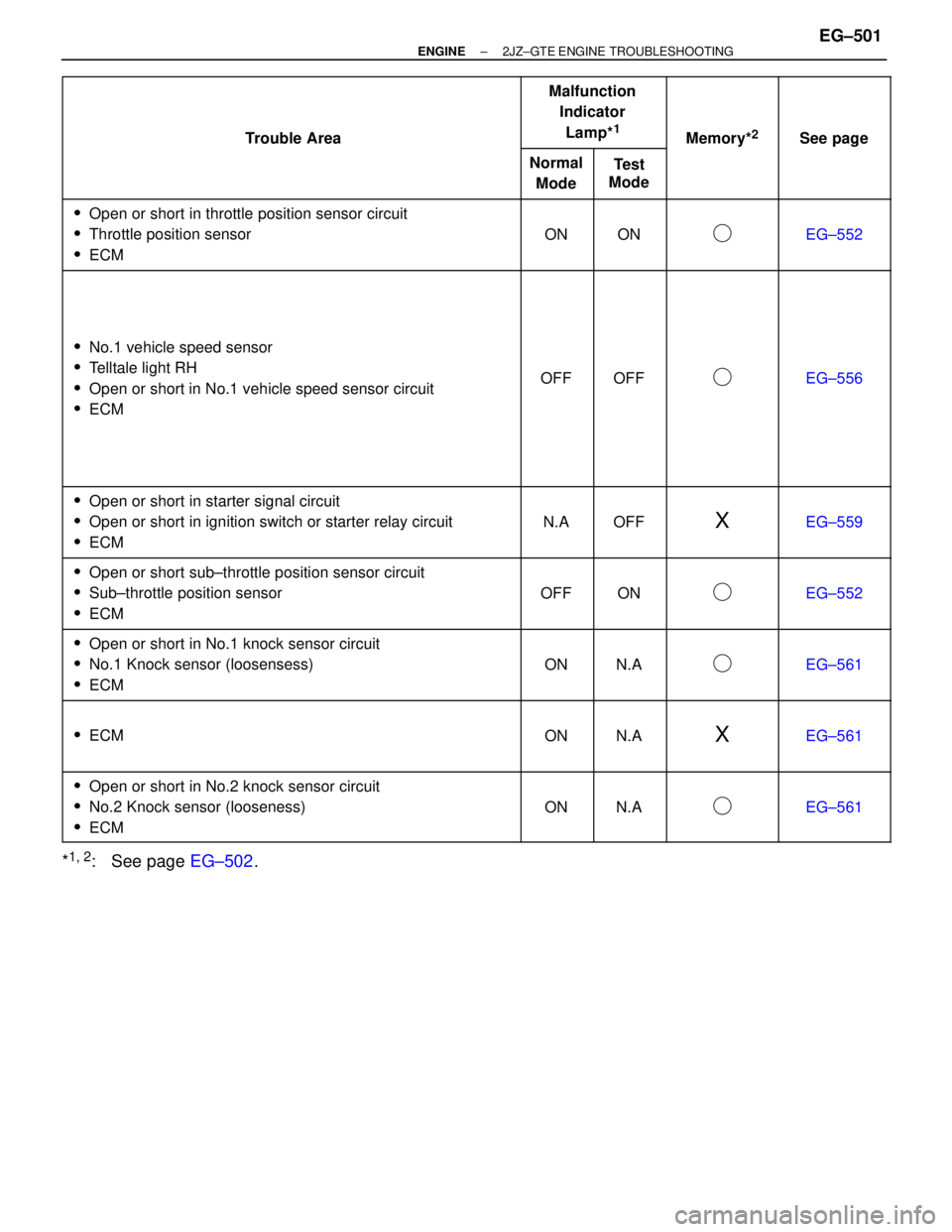
������������������� ��������������������Trouble Area
������� �
������ �
������ �������
Malfunction
Indicator
Lamp*
1
������ �
����� �
����� ������Memory*2
������ �
����� �
����� ������See page
�������������������� �
������������������� ��������������������
Trouble Area
���� �
��� ����
Normal
Mode���� �
��� ����
Test
Mode������ �
����� ������
Memory
������ �
����� ������
See page
�������������������� �
������������������� �
������������������� ��������������������
�Open or short in throttle position sensor circuit
�Throttle position sensor
�ECM
���� �
��� �
��� ����
ON
���� �
��� �
��� ����
ON
������ �
����� �
����� ������
�
������ �
����� �
����� ������
EG±552
�������������������� �
������������������� �
������������������� �
������������������� �
������������������� �
������������������� �
������������������� �
������������������� �
������������������� ��������������������
�No.1 vehicle speed sensor
�Telltale light RH
�Open or short in No.1 vehicle speed sensor circuit
�ECM
���� �
��� �
��� �
��� �
��� �
��� �
��� �
��� �
��� ����
OFF
���� �
��� �
��� �
��� �
��� �
��� �
��� �
��� �
��� ����
OFF
������ �
����� �
����� �
����� �
����� �
����� �
����� �
����� �
����� ������
�
������ �
����� �
����� �
����� �
����� �
����� �
����� �
����� �
����� ������
EG±556
�������������������� �
������������������� �
������������������� ��������������������
�Open or short in starter signal circuit
�Open or short in ignition switch or starter relay circuit
�ECM
���� �
��� �
��� ����
N.A
���� �
��� �
��� ����
OFF
������ �
����� �
����� ������
X
������ �
����� �
����� ������
EG±559
�������������������� �
������������������� �
������������������� ��������������������
�Open or short sub±throttle position sensor circuit
�Sub±throttle position sensor
�ECM
���� �
��� �
��� ����
OFF
���� �
��� �
��� ����
ON
������ �
����� �
����� ������
�
������ �
����� �
����� ������
EG±552
�������������������� �
������������������� �
������������������� ��������������������
�Open or short in No.1 knock sensor circuit
�No.1 Knock sensor (loosensess)
�ECM
���� �
��� �
��� ����
ON
���� �
��� �
��� ����
N.A
������ �
����� �
����� ������
�
������ �
����� �
����� ������
EG±561
�������������������� �
������������������� �
������������������� ��������������������
�ECM
���� �
��� �
��� ����
ON
���� �
��� �
��� ����
N.A
������ �
����� �
����� ������
X
������ �
����� �
����� ������
EG±561
�������������������� �
������������������� �
������������������� ��������������������
�Open or short in No.2 knock sensor circuit
�No.2 Knock sensor (looseness)
�ECM
���� �
��� �
��� ����
ON
���� �
��� �
��� ����
N.A
������ �
����� �
����� ������
�
������ �
����� �
����� ������
EG±561
*1,
2: See page EG±502.
± ENGINE2JZ±GTE ENGINE TROUBLESHOOTINGEG±501
Page 51 of 878
Suspect area
See page
Symptom
Engine does not crank
No initial combustion
No complete combustion
Engine cranks normally
Cold engine
Hot engine
Incorrect first idle
High engine idle speed
Low engine idle speed
Rough idling
Hunting
Hesitation/Poor acceleration
Muffler explosion (after fire)
Surging
Soon after starting
After accelerator pedal depressed
After accelerator pedal released
During A/C operation
When shifting N to D
Does not
start
Difficult to
start
Poor Idling
Engine Stall
Poor
Driveability
Back up power source circuitECM power source circuitPark/neutral position switch circuitSwitch condition signal circuitEGR systemStarter signal circuitMass air flow meter circuitInjector circuitIAC valve circuitFuel pump control circuitA/C signal circuit (Compressor circuit)Turbo control circuitVSV circuit for fuel Pressure ControlCompressionSpark plugIgnition signal circuit (Spark test)Starter and Starter relayIgnition coilEngine control module (ECM)Theft deterrent ECUA/T faulty
EG±544EG±559EG±564EG±571EG±574EG±576EG±581EG±583EG±586EG±568EG±595EG±589AC±62ST±3
,
12
IG±21IG±23IG±22EG±9AT2±101BE±123IN±35
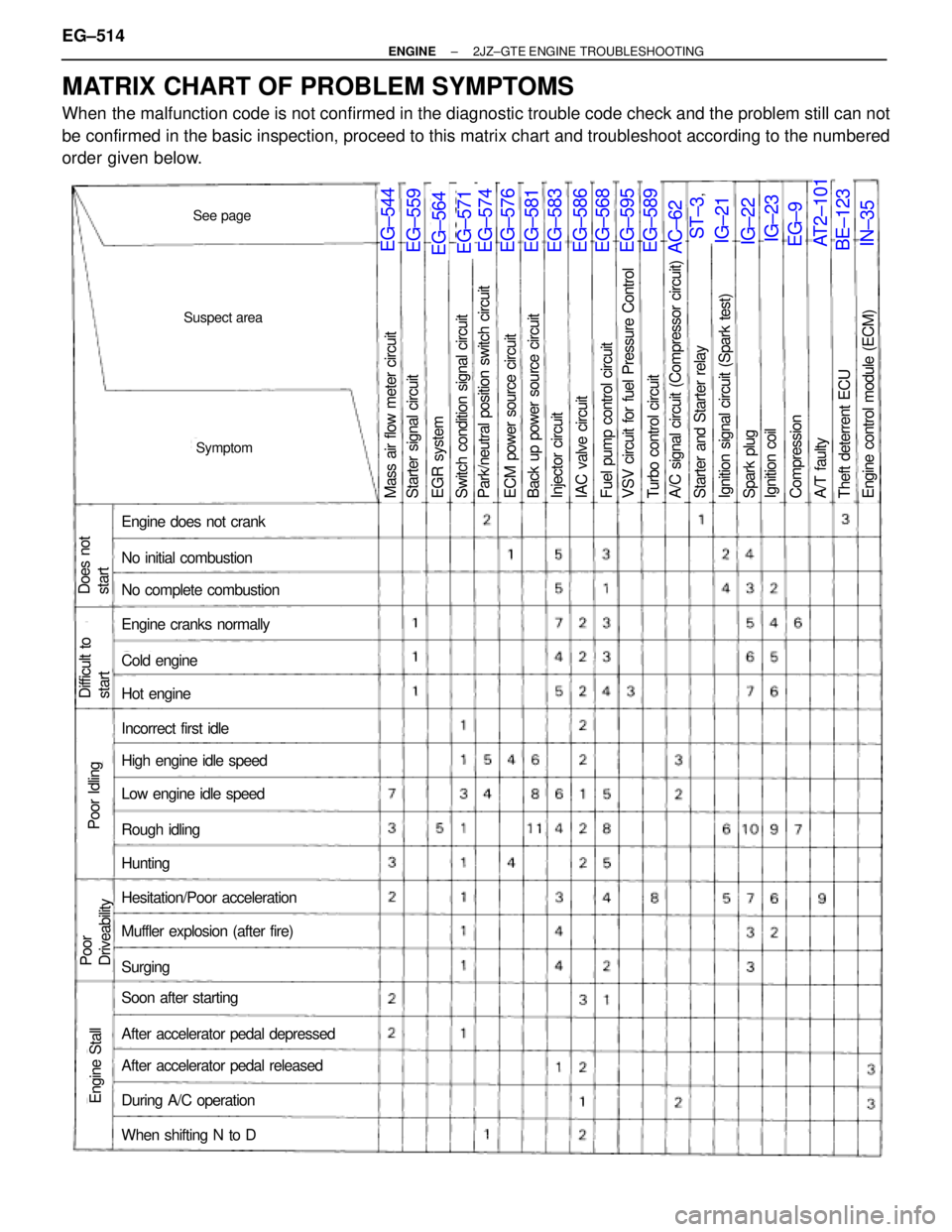
MATRIX CHART OF PROBLEM SYMPTOMS
When the malfunction code is not confirmed in the diagnostic trouble code check and the problem still can not
be confirmed in the basic inspection, proceed to this matrix chart and troubleshoot according to the numbered
order given below. EG±514
± ENGINE2JZ±GTE ENGINE TROUBLESHOOTING
Page 65 of 878
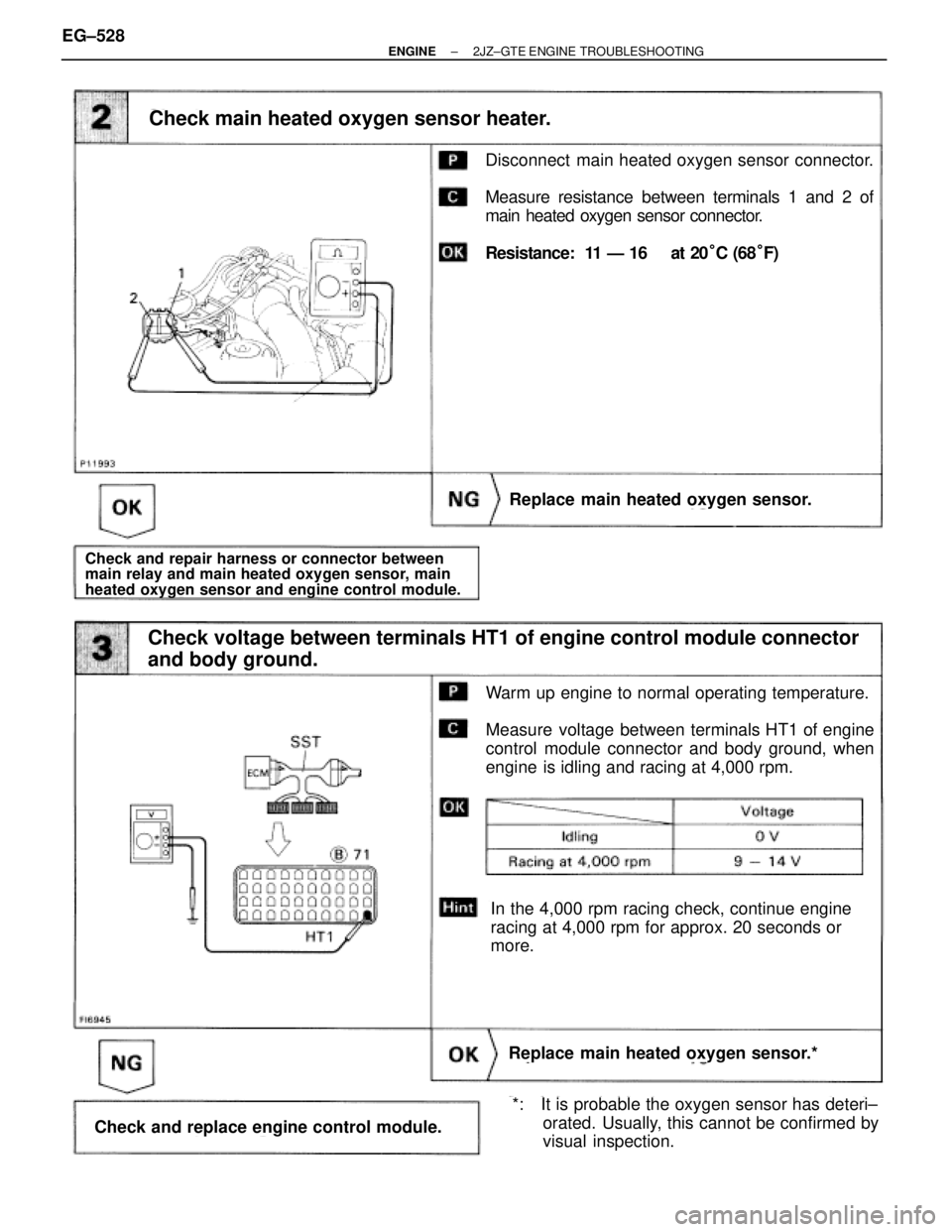
Disconnect main heated oxygen sensor connector.
Measure resistance between terminals 1 and 2 of
main heated oxygen sensor connector.
Resistance: 11 Ð 16 � at 20°C (68°F)
Check main heated oxygen sensor heater.
Replace main heated oxygen sensor.
Check and repair harness or connector between
main relay and main heated oxygen sensor, main
heated oxygen sensor and engine control module.
Warm up engine to normal operating temperature.
Measure voltage between terminals HT1 of engine
control module connector and body ground, when
engine is idling and racing at 4,000 rpm.
Check voltage between terminals HT1 of engine control module connector
and body ground.
Replace main heated oxygen sensor.*
Check and replace engine control module.
In the 4,000 rpm racing check, continue engine
racing at 4,000 rpm for approx. 20 seconds or
more.
*: It is probable the oxygen sensor has deteri±
orated. Usually, this cannot be confirmed by
visual inspection. EG±528
± ENGINE2JZ±GTE ENGINE TROUBLESHOOTING
Page 96 of 878
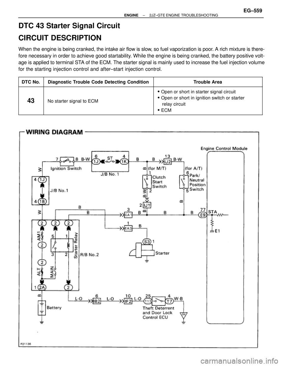
DTC 43 Starter Signal Circuit
CIRCUIT DESCRIPTION
When the engine is being cranked, the intake air flow is slow, so fuel vaporization is poor. A rich mixture is there-
fore necessary in order to achieve good startability. While the engine is being cranked, the battery positive volt-
age is applied to terminal STA of the ECM. The starter signal is mainly used to increase the fuel injection volume
for the starting injection control and after±start injection control.
����� �
���� �����DTC No.
���������������� �
��������������� ����������������Diagnostic Trouble Code Detecting Condition
���������������� �
��������������� ����������������Trouble Area
����� �
���� �
���� �
���� �����
43
���������������� �
��������������� �
��������������� �
��������������� ����������������
No starter signal to ECM
���������������� �
��������������� �
��������������� �
��������������� ����������������
�Open or short in starter signal circuit
�Open or short in ignition switch or starter
relay circuit
�ECM
± ENGINE2JZ±GTE ENGINE TROUBLESHOOTINGEG±559
Page 97 of 878
INSPECTION PROCEDURE
HINT: This diagnostic chart is based on the premise that the engine is being cranked under normal conditions.
If the engine does not crank, proceed to the matrix chart of problem symptoms on page EG±514.
(See page EG±514).
Setting the test mode.
(1) Turn ignition switch OFF.
(2) Connect terminals TE2 and E1 of DLC2.
(3) Turn ignition switch ON.
(Don't start the engine)
(4) Connect terminal TE1 and E1 of DLC2.
Check if code ª43º is output by the malfunction indi-
cator lamp.
Code ª43º is output.
Start the engine.
Check if code ª43º disappears.
Code ª43º is not output.
Check output condition of diagnostic trouble code 43.
Proceed to next circuit inspection shown on
matrix chart (See page Eg±514.)
Check and replace engine control module.
Check for open in harness and connector between engine control module
and starter relay (See page IN±30).
Repair or replace harness or connector.
EG±560± ENGINE2JZ±GTE ENGINE TROUBLESHOOTING
Page 103 of 878
INSPECTION PROCEDURE
(See page EG±310)
(See page IN±30).
(1) Connect SST (check harness ªAº).
(See page EG±510)
SST 09990±01000
(2) Warm up engine to normal operating temperature.
Measure voltage between terminal EGR of engine con-
trol module connector and body ground.
Voltage: 9 Ð 14 V
Check voltage between terminal EGR of engine control module connector
and body ground.
Check for open and short in harness and connector between EFI main relay
and VSV for EGR, VSV for EGR and engine control module (See page IN±30).
Check resistance between terminals of VSV for EGR.
Repair or replace harness or connector.
Check and replace engine control module.
Remove VSV for EGR. (See page EG±310)
Measure resistance between terminals of VSV for
EGR.
Resistance: 30 Ð 34 � at 20°C (68°F)
Replace VSV for EGR. EG±566
± ENGINE2JZ±GTE ENGINE TROUBLESHOOTING
Page 106 of 878
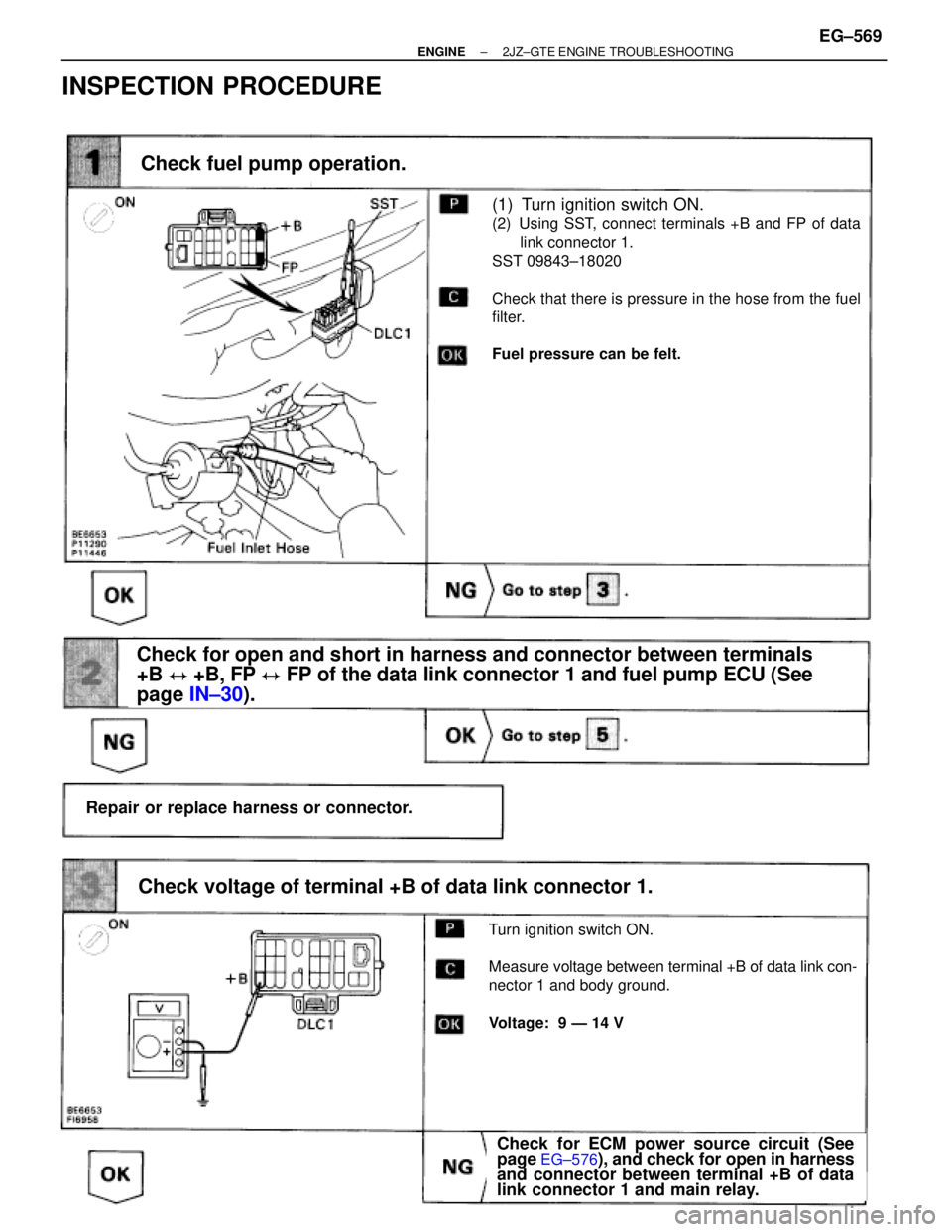
(See page IN±30).
Check for ECM power source circuit (See page
EG±576), and check for open in harness and
connector between terminal +B of data link
connector 1 and main relay.
(1) Turn ignition switch ON.
(2) Using SST, connect terminals +B and FP of data
link connector 1.
SST 09843±18020
Check that there is pressure in the hose from the fuel
filter.
Fuel pressure can be felt.
Check fuel pump operation.
Repair or replace harness or connector.
Check for open and short in harness and connector between terminals
+B � +B, FP � FP of the data link connector 1 and fuel pump ECU (See
page IN±30).
Turn ignition switch ON.
Measure voltage between terminal +B of data link con-
nector 1 and body ground.
Voltage: 9 Ð 14 V
Check voltage of terminal +B of data link connector 1.
Check for ECM power source circuit (See
page EG±576), and check for open in harness
and connector between terminal +B of data
link connector 1 and main relay.
INSPECTION PROCEDURE
± ENGINE2JZ±GTE ENGINE TROUBLESHOOTINGEG±569
Page 111 of 878
Park Neutral Position Switch Circuit
CIRCUIT DESCRIPTION
The park/neutral position switch goes on when the shift lever is in the N or P shift position. When it goes on the
terminal NSW of the ECM is grounded to body ground via the starter relay and theft deterrent ECU, thus the
terminal NSW voltage becomes 0 V. When the shift lever is in the D, 2, L or R position, the park/neutral position
switch goes off, so the voltage of ECM terminal NSW becomes positive battery voltage, the voltage of the ECM
internal power source.
If the shift lever is moved from the N position to the D position, this signal is used for air±fuel ratio correction
and for idle speed control (estimated control), etc.
When the park/neutral position switch is off, code º51º is output in the test mode diagnosis. (This is not abnor-
mal.)
EG±574± ENGINE2JZ±GTE ENGINE TROUBLESHOOTING