Page 43 of 878

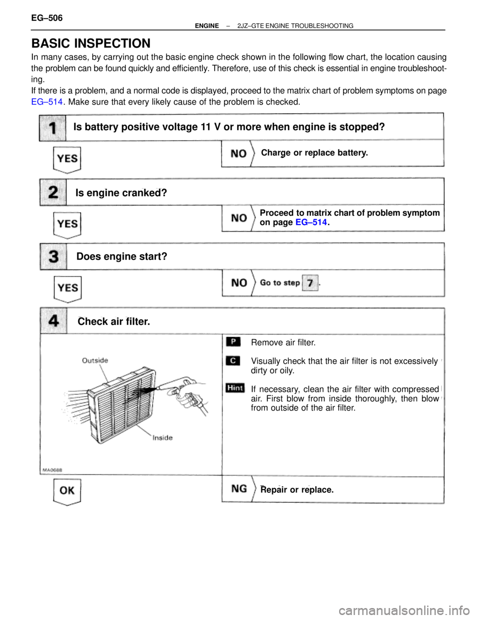
BASIC INSPECTION
In many cases, by carrying out the basic engine check shown in the following flow chart, the location causing
the problem can be found quickly and efficiently. Therefore, use of this check is essential in engine troubleshoot-
ing.
If there is a problem, and a normal code is displayed, proceed to the matrix chart of problem symptoms on page
EG±514. Make sure that every likely cause of the problem is checked.
Is battery positive voltage 11 V or more when engine is stopped?
Is engine cranked?
Does engine start?
Check air filter.
Charge or replace battery.
Proceed to matrix chart of problem symptom
on page EG±514.
Repair or replace.
Remove air filter.
Visually check that the air filter is not excessively
dirty or oily.
If necessary, clean the air filter with compressed
air. First blow from inside thoroughly, then blow
from outside of the air filter.
Charge or replace battery.
Is battery positive voltage 11 V or more when engine is stopped?
EG±506± ENGINE2JZ±GTE ENGINE TROUBLESHOOTING
Page 156 of 878
BASIC INSPECTION
In many cases, by carrying out the basic engine check shown in the following flow chart, the location causing
the problem can be found quickly and efficiently. Therefore, use of this check is essential in engine trouble-
shooting.
If there is a problem, and a normal code is displayed, proceed to the matrix chart of problem symptoms on page
EG±408. Make sure that every likely cause of the problem is checked.
EG±408.
Is battery positive voltage 11 V or more when engine is stopped?
Is engine cranked?
Does engine start?
Check air filter.
Charge or replace battery.
Proceed to matrix chart of problem symptoms
on page EG±408.
Repair or replace.
Remove air filter.
Visually check that the air filter is not excessive dirty or
oily.
If necessary, clean the air filter with compressed air. First
blow from inside thoroughly, then blow from outside of
the air filter.
EG±400± ENGINE2JZ±GE ENGINE TROUBLESHOOTING
Page 282 of 878

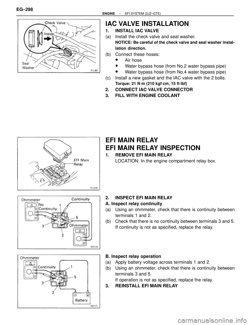
IAC VALVE INSTALLATION
1. INSTALL IAC VALVE
(a) Install the check valve and seal washer.
NOTICE: Be careful of the check valve and seal washer instal-
lation direction.
(b) Connect these hoses:
wAir hose
wWater bypass hose (from No.2 water bypass pipe)
wWater bypass hose (from No.4 water bypass pipe)
(c) Install a new gasket and the IAC valve with the 2 bolts.
Torque: 21 NVm (210 kgfVcm, 15 ftVlbf)
2. CONNECT IAC VALVE CONNECTOR
3. FILL WITH ENGINE COOLANT
EFI MAIN RELAY
EFI MAIN RELAY INSPECTION
1. REMOVE EFI MAIN RELAY
LOCATION: In the engine compartment relay box.
2. INSPECT EFI MAIN RELAY
A. Inspect relay continuity
(a) Using an ohmmeter, check that there is continuity between
terminals 1 and 2.
(b) Check that there is no continuity between terminals 3 and 5.
If continuity is not as specified, replace the relay.
B. Inspect relay operation
(a) Apply battery voltage across terminals 1 and 2.
(b) Using an ohmmeter, check that there is continuity between
terminals 3 and 5.
If operation is not as specified, replace the relay.
3. REINSTALL EFI MAIN RELAY EG±298
± ENGINESFI SYSTEM (2JZ±GTE)
Page 283 of 878
EFI NO.2 RELAY
EFI NO.2 RELAY INSPECTION
1. REMOVE EFI NO.2 RELAY
LOCATION: In the engine compartment relay box.
2. INSPECT EFI NO.2 RELAY
A. Inspect relay continuity
(a) Using an ohmmeter, check that there is continuity between
terminals 1 and 2.
(b) Check that there is no continuity between terminals 3 and 5.
If continuity is not as specified, replace the relay.
B. Inspect relay operation
(a) Apply battery voltage across terminals 1 and 2.
(b) Using an ohmmeter, check that there is continuity between
terminals 3 and 5.
If operation is not as specified, replace the relay.
3. REINSTALL EFI NO.2 RELAY
± ENGINESFI SYSTEM (2JZ±GTE)EG±299
Page 361 of 878
EFI MAIN RELAY
EFI MAIN RELAY INSPECTION
1. REMOVE EFI MAIN RELAY
LOCATION: In the engine compartment relay box.
2. INSPECT EFI MAIN RELAY
A. Inspect relay continuity
(a) Using an ohmmeter, check that there is continuity between
terminals 1 and 2.
(b) Check that there is no continuity between terminals 3 and 5.
If continuity is not as specified, replace the relay.
B. Inspect relay operation
(a) Apply battery voltage across terminals 1 and 2.
(b) Using an ohmmeter, check that there is continuity between
terminals 3 and 5.
If operation is not as specified, replace the relay.
3. REINSTALL EFI MAIN RELAY
± ENGINESFI SYSTEM (2JZ±GE)EG±235
Page 604 of 878

3
HOW TO USE THIS MANUAL
This manual provides information on the electrical circuits installed on vehicles by
dividing them into a circuit for each system.
The actual wiring of each system circuit is shown from the point where the power source
is received from the battery as far as each ground point. (All circuit diagrams are shown
with the switches in the OFF position.)
When troubleshooting any problem, first understand the operation of the circuit where
the problem was detected (see System Circuit section), the power source supplying
power to that circuit (see Power Source section), and the ground points (see Ground
Points section). See the System Outline to understand the circuit operation.
When the circuit operation is understood, begin troubleshooting of the problem circuit
to isolate the cause. Use Relay Location and Electrical Wire Routing sections to find
each part, junction block and wiring harness connectors, wiring harness and wiring
harness connectors, splice points, and ground points of each system circuit. Internal
wiring for each junction block is also provided for better understanding of connection
within a junction block.
Wiring related to each system is indicated in each system circuit by arrows (from
, to ). When overall connections are required, see the Overall Wiring Diagram
at the end of this manual.
Page 646 of 878

44
POWER SOURCE (Current Flow Chart)
The chart below shows the route by which current flows from the battery to each electrical source (Fusible Link,
Circuit Breaker, Fuse, etc.) and other parts.
The next page and following pages show the parts to which each electrical source outputs current.
50A MAIN Battery
* These are the page numbers of the first page on which
the related system is shown.
The part indicated is located somewhere in the system,
not necessarily on the page indicated here.
20A RAD No. 1(2JZ±GTE)
30A EFI No. 2Generator
(Alternator) 7.5A DOME
7.5A ALT±S
15A HAZ±HORN
15A FOG
30A EFI No. 1
120A ALT
Starter
30A ABS No. 2
7.5A TRAC
(2JZ±GTE)
30A AM230A FAN
50A HTR
60A ABS No. 1
60A POWER
50A AM1 (For USA)
60A AM1 (For Canada)
Headlight Relay
Dimmer Relay (Daytime
Running Light Relay No. 2)
Ignition SW
(AM2)Taillight Relay
(Point Side)
30A DOOR
15A STOP
10A ECU±B
30A DEFOG
Ignition SW
(AM1)
15A HEAD (LH) (For USA)
15A HEAD (LH±LWR)
(For Canada)
15A HEAD (RH) (For USA)
15A HEAD (RH±LWR)
(For Canada)
7.5A DRL
15A HEAD (LH±UPR)
(For Canada)
15A HEAD (RH±UPR)
(For Canada)
7.5A IGN
(2JZ±GTE)
(2JZ±GE)
(Canada)
(Canada) (Canada)
[LOCATION](1): J/B No. 1 (See page 20)(2): R/B No. 2 (See page 19)(3): R/B No. 4 (See page 23) 20
22 23
Page 658 of 878

58
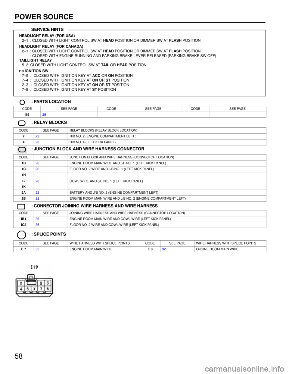
POWER SOURCE
HEADLIGHT RELAY (FOR USA)
2±1 : CLOSED WITH LIGHT CONTROL SW AT HEAD POSITION OR DIMMER SW AT FLASH POSITION
HEADLIGHT RELAY (FOR CANADA)
2±1 : CLOSED WITH LIGHT CONTROL SW AT HEAD POSITION OR DIMMER SW AT FLASH POSITION
: CLOSED WITH ENGINE RUNNING AND PARKING BRAKE LEVER RELEASED (PARKING BRAKE SW OFF)
TAILLIGHT RELAY
5±3: CLOSED WITH LIGHT CONTROL SW AT TAIL OR HEAD POSITION
I19 IGNITION SW
7±5 : CLOSED WITH IGNITION KEY AT ACC OR ON POSITION
7±4 : CLOSED WITH IGNITION KEY AT ON OR ST POSITION
2±3 : CLOSED WITH IGNITION KEY AT ON OR ST POSITION
7±8 : CLOSED WITH IGNITION KEY AT ST POSITION
: PARTS LOCATION
CODESEE PAGECODESEE PAGECODESEE PAGE
I1929
: RELAY BLOCKS
CODESEE PAGERELAY BLOCKS (RELAY BLOCK LOCATION)
222R/B NO. 2 (ENGINE COMPARTMENT LEFT )
423R/B NO. 4 (LEFT KICK PANEL)
: JUNCTION BLOCK AND WIRE HARNESS CONNECTOR
CODESEE PAGEJUNCTION BLOCK AND WIRE HARNESS (CONNECTOR LOCATION)
1B20ENGINE ROOM MAIN WIRE AND J/B NO. 1 (LEFT KICK PANEL)
1C20FLOOR NO. 2 WIRE AND J/B NO. 1 (LEFT KICK PANEL)
1H
1J20COWL WIRE AND J/B NO. 1 (LEFT KICK PANEL)
1K
20COWL WIRE AND J/B NO. 1 (LEFT KICK PANEL)
2A22BATTERY AND J/B NO. 2 (ENGINE COMPARTMENT LEFT)
2B22ENGINE ROOM MAIN WIRE AND J/B NO. 2 (ENGINE COMPARTMENT LEFT)
: CONNECTOR JOINING WIRE HARNESS AND WIRE HARNESS
CODESEE PAGEJOINING WIRE HARNESS AND WIRE HARNESS (CONNECTOR LOCATION)
IB136ENGINE ROOM MAIN WIRE AND COWL WIRE (LEFT KICK PANEL)
IC236FLOOR NO. 2 WIRE AND COWL WIRE (LEFT KICK PANEL)
: SPLICE POINTS
CODESEE PAGEWIRE HARNESS WITH SPLICE POINTSCODESEE PAGEWIRE HARNESS WITH SPLICE POINTS
E 732ENGINE ROOM MAIN WIREE 832ENGINE ROOM MAIN WIRE
SERVICE HINTS