Page 67 of 878

CIRCUIT DESCRIPTION
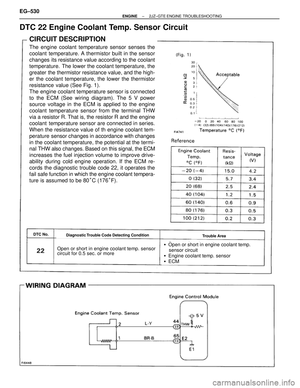
The engine coolant temperature sensor senses the
coolant temperature. A thermistor built in the sensor
changes its resistance value according to the coolant
temperature. The lower the coolant temperature, the
greater the thermistor resistance value, and the high-
er the coolant temperature, the lower the thermistor
resistance value (See Fig. 1).
The engine coolant temperature sensor is connected
to the ECM (See wiring diagram). The 5 V power
source voltage in the ECM is applied to the engine
coolant temperature sensor from the terminal THW
via a resistor R. That is, the resistor R and the engine
coolant temperature sensor are connected in series.
When the resistance value of th engine coolant tem-
perature sensor changes in accordance with changes
in the coolant temperature, the potential at the termi-
nal THW also changes. Based on this signal, the ECM
increases the fuel injection volume to improve drive-
ability during cold engine operation. If the ECM re-
cords the diagnostic trouble code 22, it operates the
fail safe function in which the engine coolant tempera-
ture is assumed to be 80°C (176°F).
Diagnostic Trouble Code Detecting ConditionDTC No.Trouble Area
Open or short in engine coolant temp. sensor
circuit for 0.5 sec. or more�Open or short in engine coolant temp.
sensor circuit
�Engine coolant temp. sensor
�ECM
DTC 22 Engine Coolant Temp. Sensor Circuit
EG±530± ENGINE2JZ±GTE ENGINE TROUBLESHOOTING
Page 73 of 878

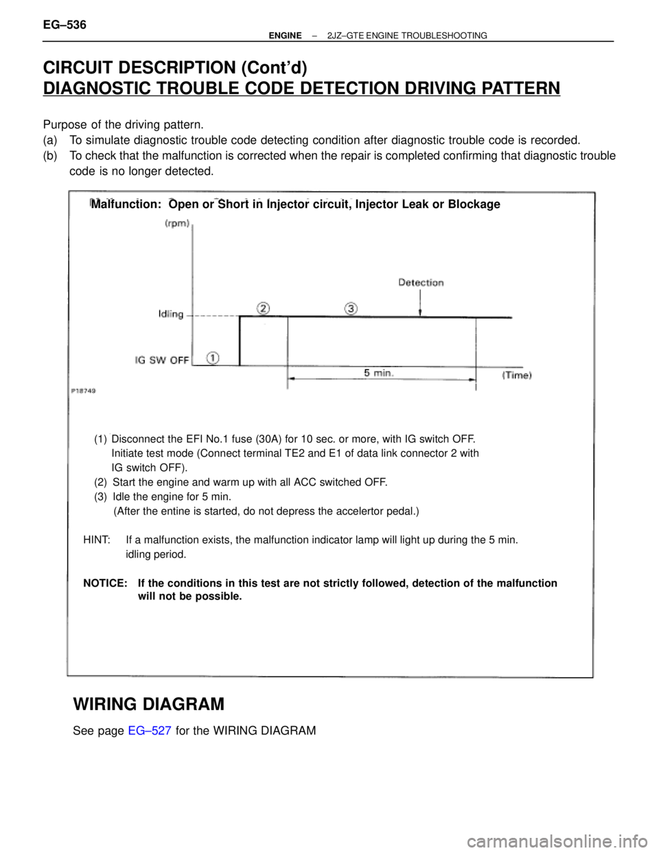
CIRCUIT DESCRIPTION (Cont'd)
DIAGNOSTIC TROUBLE CODE DETECTION DRIVING PATTERN
Purpose of the driving pattern.
(a) To simulate diagnostic trouble code detecting condition after diagnostic trouble code is recorded.
(b) To check that the malfunction is corrected when the repair is completed confirming that diagnostic trouble
code is no longer detected.
(1) Disconnect the EFI No.1 fuse (30A) for 10 sec. or more, with IG switch OFF.
Initiate test mode (Connect terminal TE2 and E1 of data link connector 2 with
IG switch OFF).
(2) Start the engine and warm up with all ACC switched OFF.
(3) Idle the engine for 5 min.
(After the entine is started, do not depress the accelertor pedal.)
HINT: If a malfunction exists, the malfunction indicator lamp will light up during the 5 min.
idling period.
NOTICE: If the conditions in this test are not strictly followed, detection of the malfunction
will not be possible.
Malfunction: Open or Short in Injector circuit, Injector Leak or Blockage
WIRING DIAGRAM
See page EG±527 for the WIRING DIAGRAM EG±536
± ENGINE2JZ±GTE ENGINE TROUBLESHOOTING
Page 116 of 878
Check for short in the harness and all the compo-
nents connected to EFI No.1 fuse (See Electrical
Wiring Diagram).
Turn ignition switch ON.
Measure voltage between terminal M±REL of en-
gine control module connector and body ground.
Voltage: 9 Ð 14 V
Check voltage between terminal M±REL of engine control module connector
and body ground
Check EFI No.1 Fuse.
Remove EFI No.1 fuse from R/B No.2.
Check continuity of EFI No.1 fuse.
Continuity
Check and replace engine control module.
± ENGINE2JZ±GTE ENGINE TROUBLESHOOTINGEG±579
Page 119 of 878
INSPECTION PROCEDURE
(See page EG±510)
Check and repair harness or connector between
engine control module and EFI No.1 fuse, EFI No.1
fuse and battery.
Remove EFI No.1 fuse from R/B No.2.
Check continuity of EFI No.1 fuse.
Continuity
Check EFI No.1 Fuse.
Check voltage between terminal BATT of engine control module connector
and body ground.
Connect SST (check harness ªAº).
See page EG±510)
SST 09990±01000
Measure voltage between terminal BATT of en-
gine control module connector and body ground.
Voltage: 9 Ð 14 V
Check for short in the harness and all the compo-
nents connected to EFI No.1 fuse (See attached
wiring diagram).
Are the diagnostic trouble codes still in the memory when the ignition switch
is turned OFF?
Check and replace engine control module.
Proceed to next circuit inspection shown on matrix
chart (See page EG±514).
EG±582± ENGINE2JZ±GTE ENGINE TROUBLESHOOTING
Page 177 of 878
Replace oxygen sensor.
Go to relevant diagnostic trouble code chart.
Are there any other codes (besides code 21 or 28) being output?
WIRING DIAGRAM
INSPECTION PROCEDURE (Except California specification vehicles)
HINT: If diagnostic trouble code º21º is output, replace oxygen sensor (Fr).
If diagnostic trouble code º28º is output, replace oxygen sensor (Rr).
± ENGINE2JZ±GE ENGINE TROUBLESHOOTINGEG±421
Page 180 of 878

DTC 22 Engine Coolant Temp. Sensor Circuit
CIRCUIT DESCRIPTION
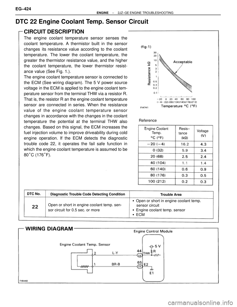
The engine coolant temperature sensor senses the
coolant temperature. A thermistor built in the sensor
changes its resistance value according to the coolant
temperature. The lower the coolant temperature, the
greater the thermistor resistance value, and the higher
the coolant temperature, the lower thermistor resist-
ance value (See Fig. 1.).
The engine coolant temperature sensor is connected to
the ECM (See wiring diagram). The 5 V power source
voltage in the ECM is applied to the engine coolant tem-
perature sensor from the terminal THW via a resistor R.
That is, the resistor R an the engine coolant temperature
sensor are connected in series. When the resistance
value of the engine coolant temperature sensor
changes in accordance with the changes in the coolant
temperature the potential at the terminal THW also
changes. Based on this signal, the ECM increases the
fuel injection volume to improve driveability during cold
engine operation. If the ECM detects the diagnostic
trouble code 22, it operates the fail safe function in
which the engine coolant temperature is assumed to be
80°C (176°F).
DTC No.Diagnostic Trouble Code Detecting ConditionTrouble Area
Open or short in engine coolant temp. sen-
sor circuit for 0.5 sec. or more
�Open or short in engine coolant temp.
sensor circuit
�Engine coolant temp. sensor
�ECM
Reference
VoltageEngine Coolant
Temp.
Resis±
tance
EG±424± ENGINE2JZ±GE ENGINE TROUBLESHOOTING
Page 186 of 878

See page
EG±421
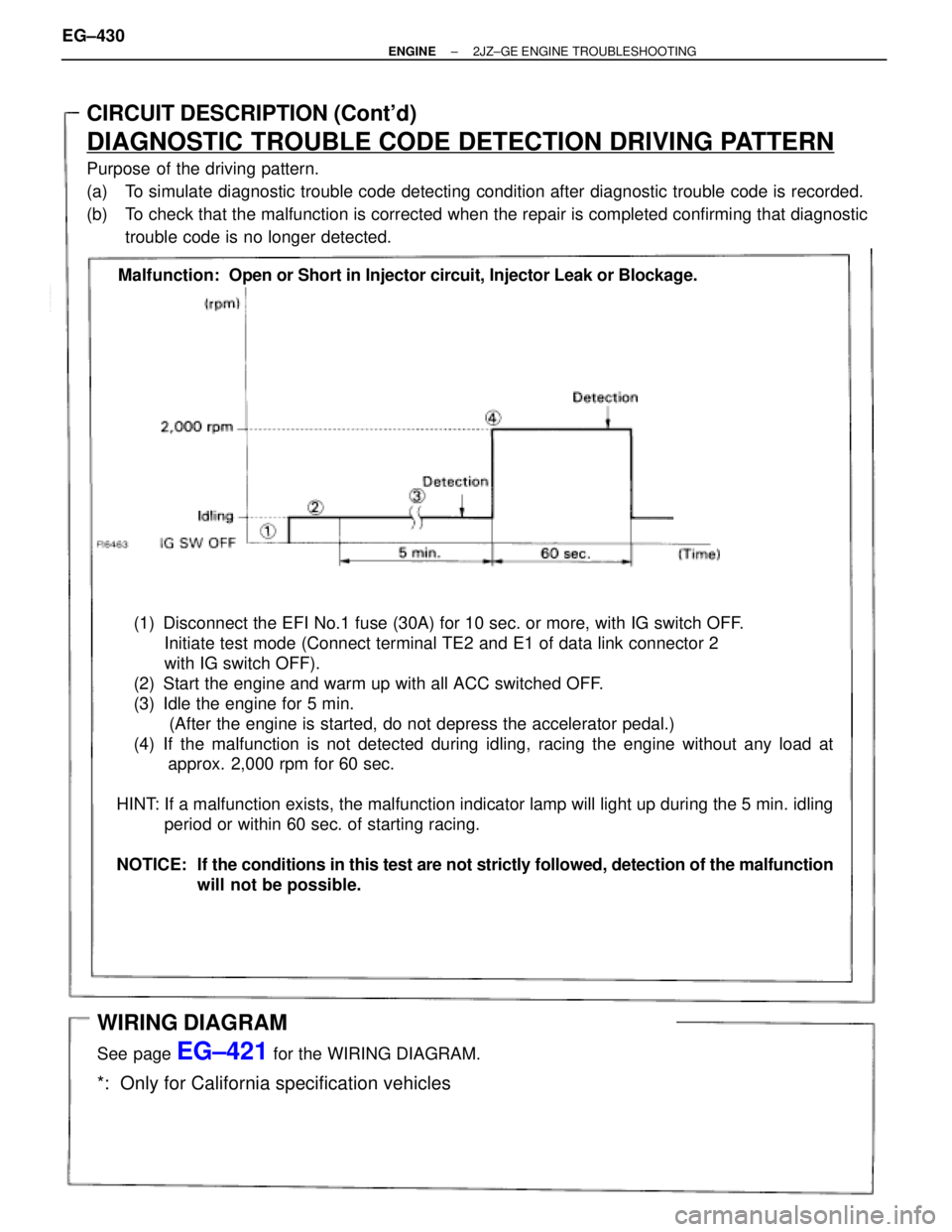
(1) Disconnect the EFI No.1 fuse (30A) for 10 sec. or more, with IG switch OFF.
Initiate test mode (Connect terminal TE2 and E1 of data link connector 2
with IG switch OFF).
(2) Start the engine and warm up with all ACC switched OFF.
(3) Idle the engine for 5 min.
(After the engine is started, do not depress the accelerator pedal.)
(4) If the malfunction is not detected during idling, racing the engine without any load at
approx. 2,000 rpm for 60 sec.
HINT: If a malfunction exists, the malfunction indicator lamp will light up during the 5 min. idling
period or within 60 sec. of starting racing.
NOTICE: If the conditions in this test are not strictly followed, detection of the malfunction
will not be possible.
CIRCUIT DESCRIPTION (Cont'd)
DIAGNOSTIC TROUBLE CODE DETECTION DRIVING PATTERN
Purpose of the driving pattern.
(a) To simulate diagnostic trouble code detecting condition after diagnostic trouble code is recorded.
(b) To check that the malfunction is corrected when the repair is completed confirming that diagnostic
trouble code is no longer detected.
Malfunction: Open or Short in Injector circuit, Injector Leak or Blockage.
WIRING DIAGRAM
See page EG±421 for the WIRING DIAGRAM.
*: Only for California specification vehicles
EG±430± ENGINE2JZ±GE ENGINE TROUBLESHOOTING
Page 223 of 878
Check IGN fuse.
Remove IGN fuse from J/B No.1.
Check continuity of IGN fuse.
Continuity
Check for short in the harness and all the com-
ponents connected to IGN fuse (See Electrical
Wiring Diagram).
Check ignition switch.
(1) Remove finish lower panel and finish lower
panel LH.
(2) Remove heater to register duct No.2.
Check continuity between terminals.
Replace ignition switch.
Check and repair harness and connector between
battery and ignition switch, ignition switch and en-
gine control module.
± ENGINE2JZ±GE ENGINE TROUBLESHOOTINGEG±467