Page 248 of 878

FUEL PUMP
ON±VEHICLE INSPECTION
1. CHECK FUEL PUMP OPERATION
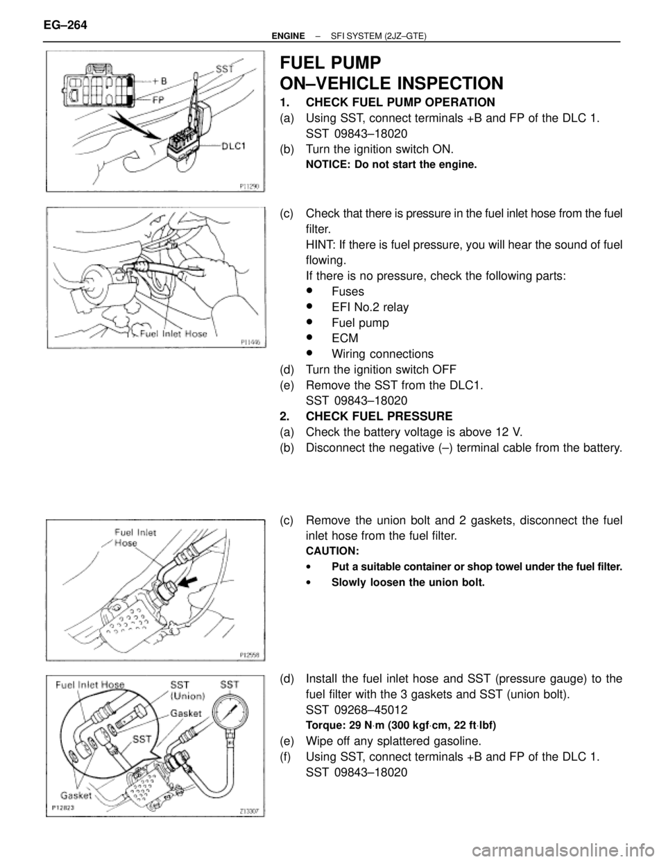
(a) Using SST, connect terminals +B and FP of the DLC 1.
SST 09843±18020
(b) Turn the ignition switch ON.
NOTICE: Do not start the engine.
(c) Check that there is pressure in the fuel inlet hose from the fuel
filter.
HINT: If there is fuel pressure, you will hear the sound of fuel
flowing.
If there is no pressure, check the following parts:
wFuses
wEFI No.2 relay
wFuel pump
wECM
wWiring connections
(d) Turn the ignition switch OFF
(e) Remove the SST from the DLC1.
SST 09843±18020
2. CHECK FUEL PRESSURE
(a) Check the battery voltage is above 12 V.
(b) Disconnect the negative (±) terminal cable from the battery.
(c) Remove the union bolt and 2 gaskets, disconnect the fuel
inlet hose from the fuel filter.
CAUTION:
wPut a suitable container or shop towel under the fuel filter.
wSlowly loosen the union bolt.
(d) Install the fuel inlet hose and SST (pressure gauge) to the
fuel filter with the 3 gaskets and SST (union bolt).
SST 09268±45012
Torque: 29 NVm (300 kgfVcm, 22 ftVlbf)
(e) Wipe off any splattered gasoline.
(f) Using SST, connect terminals +B and FP of the DLC 1.
SST 09843±18020 EG±264
± ENGINESFI SYSTEM (2JZ±GTE)
Page 596 of 878
ELECTRIC COOLING FAN (2JZ±GTE)
On±Vehicle Inspection
1. C H E C K C O O L I N G FA N O P E R AT I O N W I T H L O W
TEMPERATURE (Below 88°C (190°F))
(a) Turn the ignition switch ON.
(b) Check that the cooling fan stops.
If not, check the cooling fan relay and ECT switch, and check
for a separated connector or severed wire between the No.1
radiator fan relay and ECT switch.
(c) Disconnect the ECT switch connector.
(d) Check that the cooling fan rotates.
If not, check the No.1 radiator relay, No.2 radiator fan relay,
cooling fan, fuses, and check for short circuit between the
No.1 radiator fan relay and ECT switch.
(e) Reconnect the ECT switch connector.
2. CHECK COOLING FAN OPERATION WITH HIGH
TEMPERATURE (Above 97°C (207°F))
(a) Start the engine, and raise coolant temperature to above
97°C (207°F).
(b) Check that the cooling fan rotates.
If not, replace the ECT switch.
± ENGINECOOLING SYSTEMEG±353
Page 609 of 878
* The system shown here is an EXAMPLE ONLY. It is different to the actual circuit shown in the SYSTEM CIRCUITS SECTION.
POWER SOURCE (Current Flow Chart)
The chart below shows the route by which current flows from the battery to each electrical source (Fusible Link, Circuit
Breaker, Fuse, etc.) and other parts.
The next page and following pages show the parts to which each electrical source outputs current.
POWER SOURCE
8
HOW TO USE THIS MANUAL
The ªCurrent Flow Chartº section, describes which parts each power source (fuses, fusible links, and circuit breakers)
transmits current to. In the Power Source circuit diagram, the conditions when battery power is supplied to each system are
explained. Since all System Circuit diagrams start from the power source, the power source system must be fully understood.