1986 TOYOTA SUPRA oil level
[x] Cancel search: oil levelPage 2 of 878
PRECAUTION
1. Do not stop the engine immediately after pulling a trailer
or after high speed or uphill driving. Idle the engine for
20±120 seconds, depending on how hard the vehicle has
been driven.
2. Avoid sudden acceleration or racing immediately after
starting a cold engine.
3. Do not run the engine with air cleaner removed, as this
may cause foreign material to enter and damage the
impeller wheel operating at high speed.
4. If a turbocharger is found to be defective and must be
replaced, check for the cause, and repair or replace the
following items as necessary:
wEngine oil level and quality
wConditions under which the turbocharger was used
wOil lines leading to the turbocharger
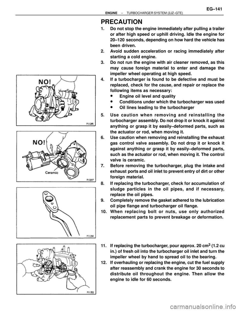
5. Use caution when removing and reinstalling the
turbocharger assembly. Do not drop it or knock it against
anything or grasp it by easily±deformed parts, such as
the actuator or rod, when moving it.
6. Use caution when removing and reinstalling the exhaust
gas control valve assembly. Do not drop it or knock it
against anything or grasp it by easily±deformed parts,
such as the actuator or rod, when moving it. The control
valve is ceramic.
7. Before removing the turbocharger, plug the intake and
exhaust ports and oil inlet to prevent entry of dirt or other
foreign material.
8. If replacing the turbocharger, check for accumulation of
sludge particles in the oil pipes, and if necessary,
replace the oil pipes.
9. Completely remove the gasket adhered to the lubrication
oil pipe flange and turbocharger oil flange.
10. Whe n re pla c ing bolt or nuts , us e only authorize d
replacement parts to prevent breakage or deformation.
11. If replacing the turbocharger, pour approx. 20 cm
3 (1.2 cu
in.) of fresh oil into the turbocharger oil inlet and turn the
impeller wheel by hand to spread oil to the bearing.
12. If overhauling or replacing the engine, cut the fuel supply
after reassembly and crank the engine for 30 seconds to
distribute oil throughout the engine. Then allow the
engine to idle for 60 seconds.
± ENGINETURBOCHARGER SYSTEM (2JZ±GTE)EG±141
Page 511 of 878
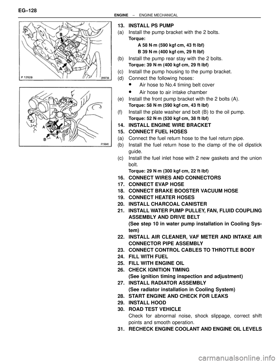
13. INSTALL PS PUMP
(a) Install the pump bracket with the 2 bolts.
Torque:
A 58 NVm (590 kgfVcm, 43 ftVlbf)
B 39 NVm (400 kgfVcm, 29 ftVlbf)
(b) Install the pump rear stay with the 2 bolts.
Torque: 39 NVm (400 kgfVcm, 29 ftVlbf)
(c) Install the pump housing to the pump bracket.
(d) Connect the following hoses:
wAir hose to No.4 timing belt cover
wAir hose to air intake chamber
(e) Install the front pump bracket with the 2 bolts (A).
Torque: 58 NVm (590 kgfVcm, 43 ftVlbf)
(f) Install the plate washer and bolt (B) to the oil pump.
Torque: 52 NVm (530 kgfVcm, 38 ftVlbf)
14. INSTALL ENGINE WIRE BRACKET
15. CONNECT FUEL HOSES
(a) Connect the fuel return hose to the fuel return pipe.
(b) Install the fuel return hose to the clamp of the oil dipstick
guide.
(c) Install the fuel inlet hose with 2 new gaskets and the union
bolt.
Torque: 29 NVm (300 kgfVcm, 22 ftVlbf)
16. CONNECT WIRES AND CONNECTORS
17. CONNECT EVAP HOSE
18. CONNECT BRAKE BOOSTER VACUUM HOSE
19. CONNECT HEATER HOSES
20. INSTALL CHARCOAL CANISTER
21. INSTALL WATER PUMP PULLEY, FAN, FLUID COUPLING
ASSEMBLY AND DRIVE BELT
(See step 10 in water pump installation in Cooling Sys-
tem)
22. INSTALL AIR CLEANER, VAF METER AND INTAKE AIR
CONNECTOR PIPE ASSEMBLY
23. CONNECT CONTROL CABLES TO THROTTLE BODY
24. FILL WITH FUEL
25. FILL WITH ENGINE OIL
26. CHECK IGNITION TIMING
(See ignition timing inspection and adjustment)
27. INSTALL RADIATOR ASSEMBLY
(See radiator installation in Cooling System)
28. START ENGINE AND CHECK FOR LEAKS
29. INSTALL HOOD
30. ROAD TEST VEHICLE
Check for abnormal noise, shock slippage, correct shift
points and smooth operation.
31. RECHECK ENGINE COOLANT AND ENGINE OIL LEVELS EG±128
± ENGINEENGINE MECHANICAL
Page 515 of 878

31. CHECK IGNITION TIMING
(See ignition timing inspection)
32. INSTALL RADIATOR ASSEMBLY
(See radiator installation in Cooling System)
33. INSTALL HOOD
34. ROAD TEST VEHICLE
Check for abnormal noise, shock slippage, correct shift
points and smooth operation.
35. RECHECK ENGINE COOLANT AND ENGINE OIL LEVELS EG±132
± ENGINEENGINE MECHANICAL
Page 525 of 878
OIL PRESSURE CHECK
1. CHECK OIL QUALITY
Check the oil for deterioration, entry of water, discoloring or
thinning.
If oil quality is visibly poor, replace the oil.
2. CHECK ENGINE OIL LEVEL
The oil level should be between the ºLº and ºFº marks on the
dipstick.
If low, check for the leakage and add oil up to ºFº mark.
3. REMOVE ENGINE UNDER COVER
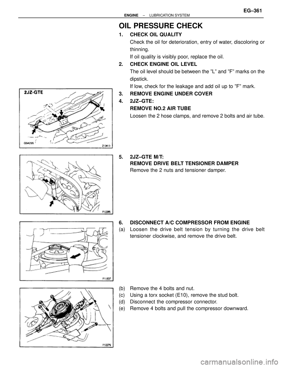
4. 2JZ±GTE:
REMOVE NO.2 AIR TUBE
Loosen the 2 hose clamps, and remove 2 bolts and air tube.
5. 2JZ±GTE M/T:
REMOVE DRIVE BELT TENSIONER DAMPER
Remove the 2 nuts and tensioner damper.
6. DISCONNECT A/C COMPRESSOR FROM ENGINE
(a) Loosen the drive belt tension by turning the drive belt
tensioner clockwise, and remove the drive belt.
(b) Remove the 4 bolts and nut.
(c) Using a torx socket (E10), remove the stud bolt.
(d) Disconnect the compressor connector.
(e) Remove 4 bolts and pull the compressor downward.
± ENGINELUBRICATION SYSTEMEG±361
Page 528 of 878
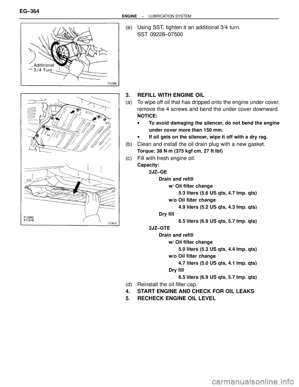
(e) Using SST, tighten it an additional 3/4 turn.
SST 09228±07500
3. REFILL WITH ENGINE OIL
(a) To wipe off oil that has dripped onto the engine under cover,
remove the 4 screws and bend the under cover downward.
NOTICE:
wTo avoid damaging the silencer, do not bend the engine
under cover more than 150 mm.
wIf oil gets on the silencer, wipe it off with a dry rag.
(b) Clean and install the oil drain plug with a new gasket.
Torque: 38 NVm (375 kgfVcm, 27 ftVlbf)
(c) Fill with fresh engine oil.
Capacity:
2JZ±GE
Drain and refill
w/ Oil filter change
5.3 liters (5.6 US qts, 4.7 Imp. qts)
w/o Oil filter change
4.9 liters (5.2 US qts, 4.3 Imp. qts)
Dry fill
6.5 liters (6.9 US qts, 5.7 Imp. qts)
2JZ±GTE
Drain and refill
w/ Oil filter change
5.0 liters (5.3 US qts, 4.4 Imp. qts)
w/o Oil filter change
4.7 liters (5.0 US qts, 4.1 Imp. qts)
Dry fill
6.5 liters (6.9 US qts, 5.7 Imp. qts)
(d) Reinstall the oil filler cap.
4. START ENGINE AND CHECK FOR OIL LEAKS
5. RECHECK ENGINE OIL LEVEL EG±364
± ENGINELUBRICATION SYSTEM
Page 531 of 878
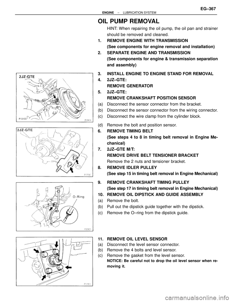
OIL PUMP REMOVAL
HINT: When repairing the oil pump, the oil pan and strainer
should be removed and cleaned.
1. REMOVE ENGINE WITH TRANSMISSION
(See components for engine removal and installation)
2. SEPARATE ENGINE AND TRANSMISSION
(See components for engine & transmission separation
and assembly)
3. INSTALL ENGINE TO ENGINE STAND FOR REMOVAL
4. 2JZ±GTE:
REMOVE GENERATOR
5. 2JZ±GTE:
REMOVE CRANKSHAFT POSITION SENSOR
(a) Disconnect the sensor connector from the bracket.
(b) Disconnect the sensor connector from the wiring connector.
(c) Disconnect the wire clamp from the cylinder block.
(d) Remove the bolt and position sensor.
6. REMOVE TIMING BELT
(See steps 4 to 8 in timing belt removal in Engine Me-
chanical)
7. 2JZ±GTE M/T:
REMOVE DRIVE BELT TENSIONER BRACKET
Remove the 2 nuts and tensioner bracket.
8. REMOVE IDLER PULLEY
(See step 15 in timing belt removal in Engine Mechanical)
9. REMOVE CRANKSHAFT TIMING PULLEY
(See step 17 in timing belt removal in Engine Mechanical)
10. REMOVE OIL DIPSTICK AND GUIDE ASSEMBLY
(a) Remove the bolt.
(b) Pull out the dipstick guide together with the dipstick.
(c) Remove the O±ring from the dipstick guide.
11. REMOVE OIL LEVEL SENSOR
(a) Disconnect the level sensor connector.
(b) Remove the 4 bolts and level sensor.
(c) Remove the gasket from the level sensor.
NOTICE: Be careful not to drop the oil level sensor when re-
moving it.
± ENGINELUBRICATION SYSTEMEG±367
Page 539 of 878
6. INSTALL OIL STRAINER
Install a new gasket and the oil strainer with the bolt and 2
nuts.
Torque: 8.8 NVm (90 kgfVcm, 78 in.Vlbf)
7. INSTALL NO.2 OIL PAN
(a) Remove any old packing (FIPG) material and be careful not
to drop any oil on the contact surfaces of the No.1 and No.2
oil pans.
wUsing a razor blade and gasket scraper, remove all the
old packing (FIPG) material from the gasket surfaces
and sealing groove.
wThoroughly clean all components to remove all the
debris.
wUsing a non±residue solvent, clean both sealing
surfaces.
NOTICE: Do not use a solvent which will affect the painted sur-
faces.
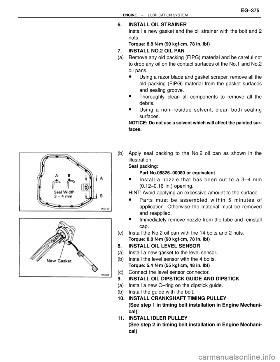
(b) Apply seal packing to the No.2 oil pan as shown in the
illustration.
Seal packing:
Part No.08826±00080 or equivalent
wInstall a nozzle that has been cut to a 3±4 mm
(0.12±0.16 in.) opening.
HINT: Avoid applying an excessive amount to the surface.
wParts must be assembled within 5 minutes of
application. Otherwise the material must be removed
and reapplied.
wImmediately remove nozzle from the tube and reinstall
cap.
(c) Install the No.2 oil pan with the 14 bolts and 2 nuts.
Torque: 8.8 NVm (90 kgfVcm, 78 in.Vlbf)
8. INSTALL OIL LEVEL SENSOR
(a) Install a new gasket to the level sensor.
(b) Install the level sensor with the 4 bolts.
Torque: 5.4 NVm (55 kgfVcm, 48 in.Vlbf)
(c) Connect the level sensor connector.
9. INSTALL OIL DIPSTICK GUIDE AND DIPSTICK
(a) Install a new O±ring on the dipstick guide.
(b) Install the guide with the bolt.
10. INSTALL CRANKSHAFT TIMING PULLEY
(See step 1 in timing belt installation in Engine Mechani-
cal)
11. INSTALL IDLER PULLEY
(See step 2 in timing belt installation in Engine Mechani-
cal)
± ENGINELUBRICATION SYSTEMEG±375
Page 542 of 878
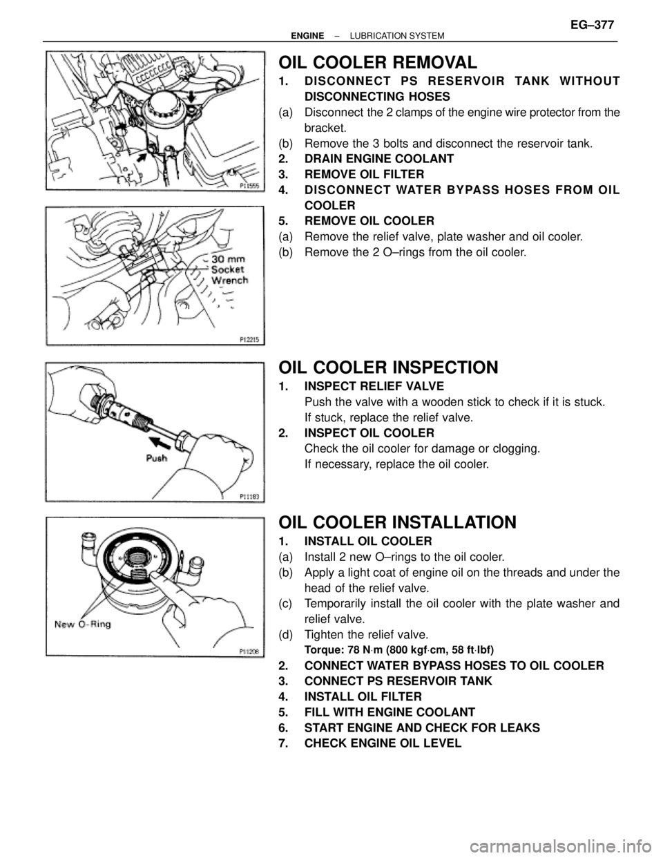
OIL COOLER REMOVAL
1. DISCONNECT PS RESERVOIR TANK WITHOUT
DISCONNECTING HOSES
(a) Disconnect the 2 clamps of the engine wire protector from the
bracket.
(b) Remove the 3 bolts and disconnect the reservoir tank.
2. DRAIN ENGINE COOLANT
3. REMOVE OIL FILTER
4. DISCONNECT WATER BYPASS HOSES FROM OIL
COOLER
5. REMOVE OIL COOLER
(a) Remove the relief valve, plate washer and oil cooler.
(b) Remove the 2 O±rings from the oil cooler.
OIL COOLER INSPECTION
1. INSPECT RELIEF VALVE
Push the valve with a wooden stick to check if it is stuck.
If stuck, replace the relief valve.
2. INSPECT OIL COOLER
Check the oil cooler for damage or clogging.
If necessary, replace the oil cooler.
OIL COOLER INSTALLATION
1. INSTALL OIL COOLER
(a) Install 2 new O±rings to the oil cooler.
(b) Apply a light coat of engine oil on the threads and under the
head of the relief valve.
(c) Temporarily install the oil cooler with the plate washer and
relief valve.
(d) Tighten the relief valve.
Torque: 78 NVm (800 kgfVcm, 58 ftVlbf)
2. CONNECT WATER BYPASS HOSES TO OIL COOLER
3. CONNECT PS RESERVOIR TANK
4. INSTALL OIL FILTER
5. FILL WITH ENGINE COOLANT
6. START ENGINE AND CHECK FOR LEAKS
7. CHECK ENGINE OIL LEVEL
± ENGINELUBRICATION SYSTEMEG±377