1986 TOYOTA SUPRA check engine
[x] Cancel search: check enginePage 2 of 878
PRECAUTION
1. Do not stop the engine immediately after pulling a trailer
or after high speed or uphill driving. Idle the engine for
20±120 seconds, depending on how hard the vehicle has
been driven.
2. Avoid sudden acceleration or racing immediately after
starting a cold engine.
3. Do not run the engine with air cleaner removed, as this
may cause foreign material to enter and damage the
impeller wheel operating at high speed.
4. If a turbocharger is found to be defective and must be
replaced, check for the cause, and repair or replace the
following items as necessary:
wEngine oil level and quality
wConditions under which the turbocharger was used
wOil lines leading to the turbocharger
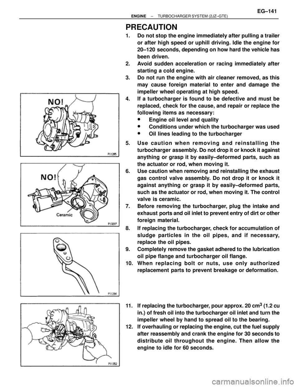
5. Use caution when removing and reinstalling the
turbocharger assembly. Do not drop it or knock it against
anything or grasp it by easily±deformed parts, such as
the actuator or rod, when moving it.
6. Use caution when removing and reinstalling the exhaust
gas control valve assembly. Do not drop it or knock it
against anything or grasp it by easily±deformed parts,
such as the actuator or rod, when moving it. The control
valve is ceramic.
7. Before removing the turbocharger, plug the intake and
exhaust ports and oil inlet to prevent entry of dirt or other
foreign material.
8. If replacing the turbocharger, check for accumulation of
sludge particles in the oil pipes, and if necessary,
replace the oil pipes.
9. Completely remove the gasket adhered to the lubrication
oil pipe flange and turbocharger oil flange.
10. Whe n re pla c ing bolt or nuts , us e only authorize d
replacement parts to prevent breakage or deformation.
11. If replacing the turbocharger, pour approx. 20 cm
3 (1.2 cu
in.) of fresh oil into the turbocharger oil inlet and turn the
impeller wheel by hand to spread oil to the bearing.
12. If overhauling or replacing the engine, cut the fuel supply
after reassembly and crank the engine for 30 seconds to
distribute oil throughout the engine. Then allow the
engine to idle for 60 seconds.
± ENGINETURBOCHARGER SYSTEM (2JZ±GTE)EG±141
Page 3 of 878
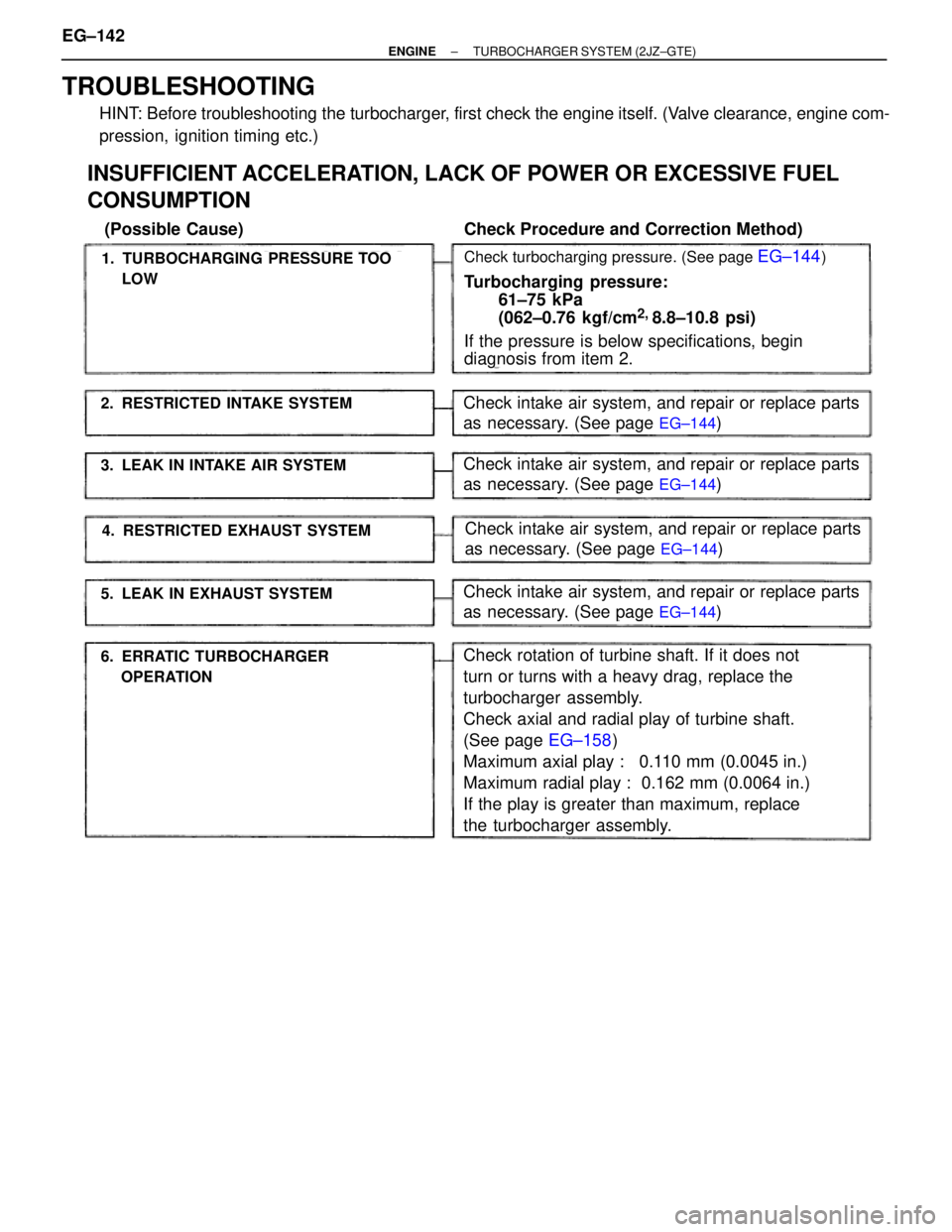
TROUBLESHOOTING
HINT: Before troubleshooting the turbocharger, first check the engine itself. (Valve clearance, engine com-
pression, ignition timing etc.)
Check intake air system, and repair or replace parts
as necessary. (See page
EG±144)
1. TURBOCHARGING PRESSURE TOO
LOW
2. RESTRICTED INTAKE SYSTEM
6. ERRATIC TURBOCHARGER
OPERATION
3. LEAK IN INTAKE AIR SYSTEM
4. RESTRICTED EXHAUST SYSTEM
5. LEAK IN EXHAUST SYSTEM
INSUFFICIENT ACCELERATION, LACK OF POWER OR EXCESSIVE FUEL
CONSUMPTION
(Possible Cause) Check Procedure and Correction Method)
Check turbocharging pressure. (See page EG±144)
Turbocharging pressure:
61±75 kPa
(062±0.76 kgf/cm
2,
8.8±10.8 psi)
If the pressure is below specifications, begin
diagnosis from item 2.
Check intake air system, and repair or replace parts
as necessary. (See page
EG±144)
Check intake air system, and repair or replace parts
as necessary. (See page
EG±144)
Check intake air system, and repair or replace parts
as necessary. (See page
EG±144)
Check rotation of turbine shaft. If it does not
turn or turns with a heavy drag, replace the
turbocharger assembly.
Check axial and radial play of turbine shaft.
(See page EG±158)
Maximum axial play : 0.110 mm (0.0045 in.)
Maximum radial play : 0.162 mm (0.0064 in.)
If the play is greater than maximum, replace
the turbocharger assembly. EG±142
± ENGINETURBOCHARGER SYSTEM (2JZ±GTE)
Page 4 of 878
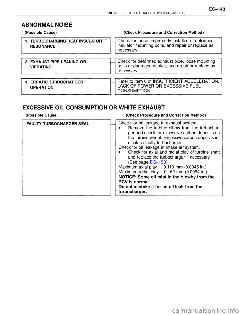
1. TURBOCHARGING HEAT INSULATOR
RESONANCE
2. EXHAUST PIPE LEAKING OR
VIBRATING
3. ERRATIC TURBOCHARGER
OPERATION
ABNORMAL NOISE
(Possible Cause) (Check Procedure and Correction Method)
Check for loose, improperly installed or deformed
insulator mounting bolts, and repair or replace as
necessary.
Check for deformed exhaust pipe, loose mounting
bolts or damaged gasket, and repair or replace as
necessary.
Refer to item 6 of INSUFFICIENT ACCELERATION,
LACK OF POWER OR EXCESSIVE FUEL
CONSUMPTION.
EXCESSIVE OIL CONSUMPTION OR WHITE EXHAUST
(Possible Cause) (Check Procedure and Correction Method)
FAULTY TURBOCHARGER SEALCheck for oil leakage in exhaust system.
wRemove the turbine elbow from the turbochar-
ger and check for excessive carbon deposits on
the turbine wheel. Excessive carbon deposits in-
dicate a faulty turbocharger.
Check for oil leakage in intake air system.
wCheck for axial and radial play of turbine shaft
and replace the turbocharger if necessary.
(See page EG±158)
Maximum axial play : 0.110 mm (0.0045 in.)
Maximum radial play : 0.162 mm (0.0064 in.)
NOTICE: Some oil mist in the blowby from the
PCV is normal.
Do not mistake it for an oil leak from the
turbocharger.
± ENGINETURBOCHARGER SYSTEM (2JZ±GTE)EG±143
Page 5 of 878
TURBOCHARGER
On±Vehicle Inspection
1. INSPECT INTAKE AIR SYSTEM
Check for leakage or clogging between the air cleaner and
turbocharger inlet and between the turbocharger outlet and
cylinder head.
wClogged air cleaner .... Clean or replace air filter
wHoses collapsed or deformed .... Repair or replace
wLeakage from connections .... Check each
connection and repair
wCracks in components Check and replace
2. INSPECT EXHAUST SYSTEM
Check for leakage or clogging between the cylinder head and
turbocharger inlet and between the turbocharger outlet and
exhaust pipe.
wDeformed components Repair or replace
wForeign material in passages Remove
wLeakage from components Repair or replace
wCracks in components Check and replace
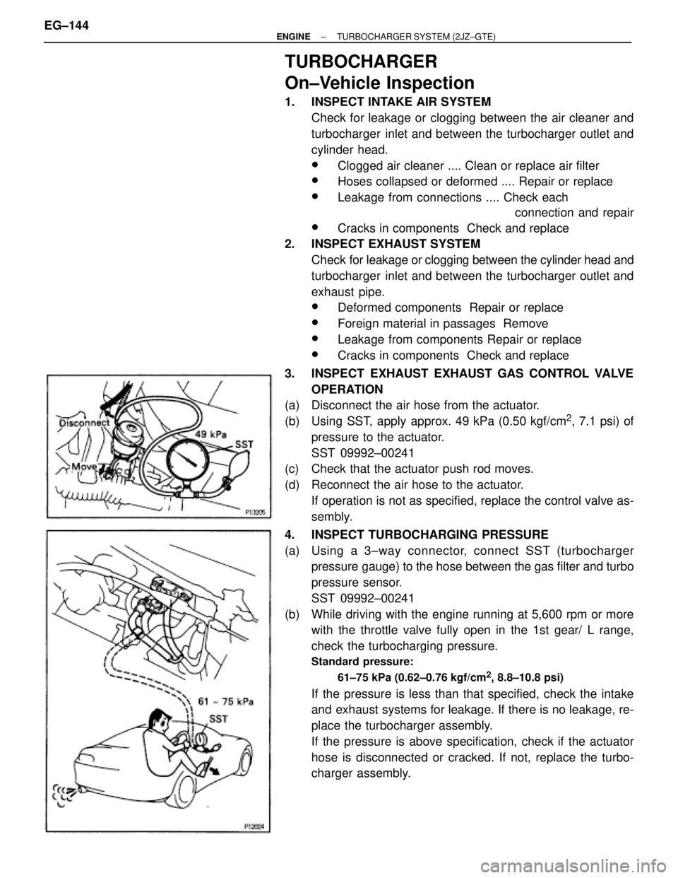
3. INSPECT EXHAUST EXHAUST GAS CONTROL VALVE
OPERATION
(a) Disconnect the air hose from the actuator.
(b) Using SST, apply approx. 49 kPa (0.50 kgf/cm
2, 7.1 psi) of
pressure to the actuator.
SST 09992±00241
(c) Check that the actuator push rod moves.
(d) Reconnect the air hose to the actuator.
If operation is not as specified, replace the control valve as-
sembly.
4. INSPECT TURBOCHARGING PRESSURE
(a) Using a 3±way connector, connect SST (turbocharger
pressure gauge) to the hose between the gas filter and turbo
pressure sensor.
SST 09992±00241
(b) While driving with the engine running at 5,600 rpm or more
with the throttle valve fully open in the 1st gear/ L range,
check the turbocharging pressure.
Standard pressure:
61±75 kPa (0.62±0.76 kgf/cm
2, 8.8±10.8 psi)
If the pressure is less than that specified, check the intake
and exhaust systems for leakage. If there is no leakage, re-
place the turbocharger assembly.
If the pressure is above specification, check if the actuator
hose is disconnected or cracked. If not, replace the turbo-
charger assembly. EG±144
± ENGINETURBOCHARGER SYSTEM (2JZ±GTE)
Page 8 of 878
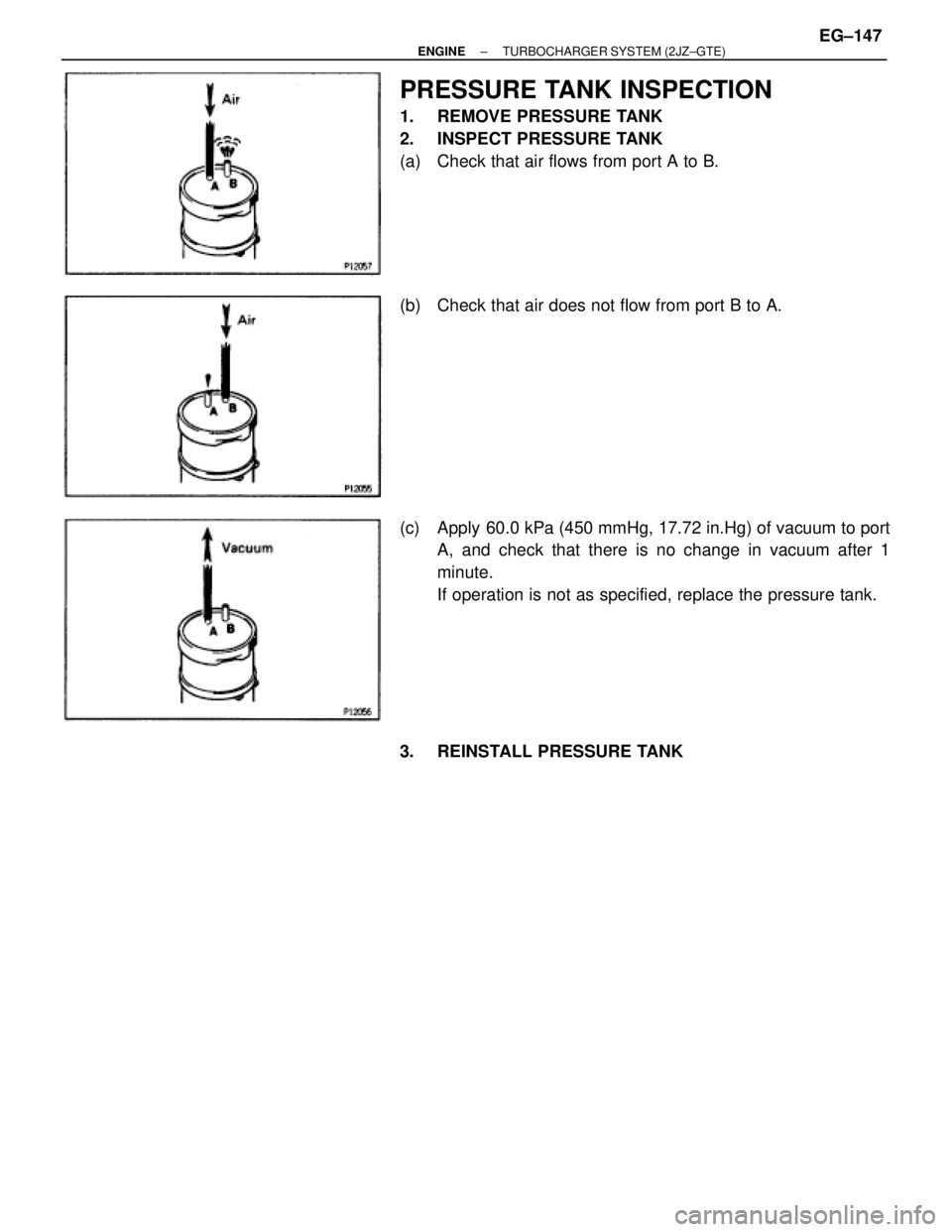
PRESSURE TANK INSPECTION
1. REMOVE PRESSURE TANK
2. INSPECT PRESSURE TANK
(a) Check that air flows from port A to B.
(b) Check that air does not flow from port B to A.
(c) Apply 60.0 kPa (450 mmHg, 17.72 in.Hg) of vacuum to port
A, and check that there is no change in vacuum after 1
minute.
If operation is not as specified, replace the pressure tank.
3. REINSTALL PRESSURE TANK
± ENGINETURBOCHARGER SYSTEM (2JZ±GTE)EG±147
Page 19 of 878
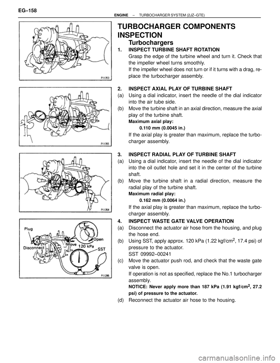
TURBOCHARGER COMPONENTS
INSPECTION
Turbochargers
1. INSPECT TURBINE SHAFT ROTATION
Grasp the edge of the turbine wheel and turn it. Check that
the impeller wheel turns smoothly.
If the impeller wheel does not turn or if it turns with a drag, re-
place the turbocharger assembly.
2. INSPECT AXIAL PLAY OF TURBINE SHAFT
(a) Using a dial indicator, insert the needle of the dial indicator
into the air tube side.
(b) Move the turbine shaft in an axial direction, measure the axial
play of the turbine shaft.
Maximum axial play:
0.110 mm (0.0045 in.)
If the axial play is greater than maximum, replace the turbo-
charger assembly.
3. INSPECT RADIAL PLAY OF TURBINE SHAFT
(a) Using a dial indicator, insert the needle of the dial indicator
into the oil outlet hole and set it in the center of the turbine
shaft.
(b) Move the turbine shaft in a radial direction, measure the
radial play of the turbine shaft.
Maximum radial play:
0.162 mm (0.0064 in.)
If the axial play is greater than maximum, replace the turbo-
charger assembly.
4. INSPECT WASTE GATE VALVE OPERATION
(a) Disconnect the actuator air hose from the housing, and plug
the hose end.
(b) Using SST, apply approx. 120 kPa (1.22 kgf/cm
2, 17.4 psi) of
pressure to the actuator.
SST 09992±00241
(c) Move the actuator push rod, and check that the waste gate
valve is open.
If operation is not as specified, replace the No.1 turbocharger
assembly.
NOTICE: Never apply more than 187 kPa (1.91 kgf/cm2, 27.2
psi) of pressure to the actuator.
(d) Reconnect the actuator air hose to the housing. EG±158
± ENGINETURBOCHARGER SYSTEM (2JZ±GTE)
Page 20 of 878
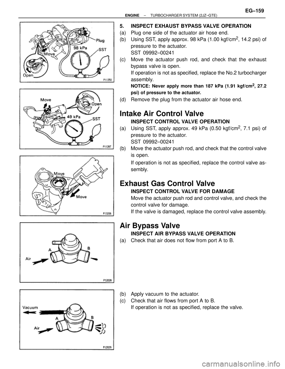
5. INSPECT EXHAUST BYPASS VALVE OPERATION
(a) Plug one side of the actuator air hose end.
(b) Using SST, apply approx. 98 kPa (1.00 kgf/cm
2, 14.2 psi) of
pressure to the actuator.
SST 09992±00241
(c) Move the actuator push rod, and check that the exhaust
bypass valve is open.
If operation is not as specified, replace the No.2 turbocharger
assembly.
NOTICE: Never apply more than 187 kPa (1.91 kgf/cm2, 27.2
psi) of pressure to the actuator.
(d) Remove the plug from the actuator air hose end.
Intake Air Control Valve
INSPECT CONTROL VALVE OPERATION
(a) Using SST, apply approx. 49 kPa (0.50 kgf/cm
2, 7.1 psi) of
pressure to the actuator.
SST 09992±00241
(b) Move the actuator push rod, and check that the control valve
is open.
If operation is not as specified, replace the control valve as-
sembly.
Exhaust Gas Control Valve
INSPECT CONTROL VALVE FOR DAMAGE
Move the actuator push rod and control valve, and check the
control valve for damage.
If the valve is damaged, replace the control valve assembly.
Air Bypass Valve
INSPECT AIR BYPASS VALVE OPERATION
(a) Check that air does not flow from port A to B.
(b) Apply vacuum to the actuator.
(c) Check that air flows from port A to B.
If operation is not as specified, replace the valve.
± ENGINETURBOCHARGER SYSTEM (2JZ±GTE)EG±159
Page 25 of 878
P.
EG±489
P. EG±491, P.
EG±493
P.
EG±492
P. IN±24
P.
EG±492
P.
EG±506
P.
EG±494
P.
EG±514
P.
EG±515
P.
EG±505
Vehicle Brought to Workshop
Customer Problem Analysis
Check and Clear Diagnostic Trouble Code (Precheck)
Setting the Test Mode Diagnosis
Problem Symptom Confirmation
Malfunction does not occur
Symptom Simulation
Diagnostic Trouble Code Check
Malfunction code
Diagnostic Trouble Code Chart
Malfunction
occurs
Normal code
Basic Inspection
Matrix Chart of Problem Symptoms
Circuit Inspection
Check for Intermittent problemsParts Inspection
Identification of Problem
Adjustment Repair
Conformation Test
Diagnostic steps permitting the use of
the TOYOTA hand±held tester or
TOYOTA break±out box.
Titles insideare titles of pages
in this manual, with the page number
indicated in the bottom portion.
See the indicated pages for de-
tailed explanations.
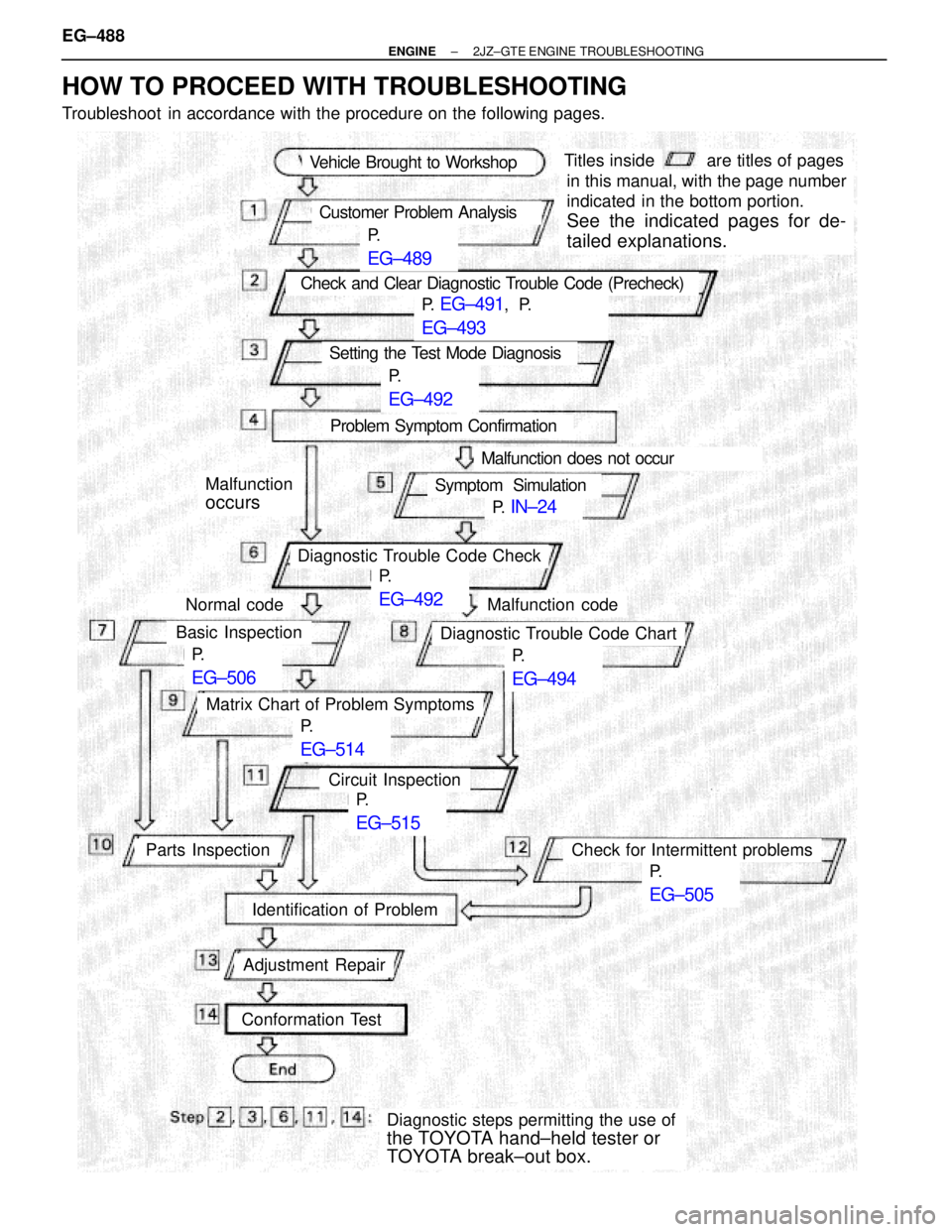
HOW TO PROCEED WITH TROUBLESHOOTING
Troubleshoot in accordance with the procedure on the following pages. EG±488
± ENGINE2JZ±GTE ENGINE TROUBLESHOOTING