Page 452 of 878

33. INSTALL NO.2 FRONT EXHAUST PIPE
(See step 6 in engine installation in Engine Mechanical)
34. INSTALL DRIVE BELT
35. INSTALL AIR CLEANER, VAF METER AND INTAKE AIR
CONNECTOR PIPE ASSEMBLY
(See step 22 in engine installation in Engine Mechanical)
36. INSTALL AIR CLEANER DUCT
37. FILL WITH ENGINE COOLANT
38. START ENGINE AND CHECK FOR LEAKS
39. CHECK IGNITION TIMING
(See steps 8 to 12 in distributor installation in Ignition
System)
40. INSTALL ENGINE UNDER COVER
41. PERFORM ROAD TEST
Check for abnormal noise, shock, slippage, correct shift
points and smooth operation.
42. RECHECK ENGINE COOLANT LEVEL
CYLINDER HEAD INSTALLATION
(2JZ±GTE)
1. INSTALL CYLINDER HEAD
(See step 1 in cylinder head installation (2JZ±GE))
2. INSTALL CAMSHAFTS
(See step 2 ((a) to (m)) in cylinder head installation (2JZ±
GE))
3. CHECK AND ADJUST VALVE CLEARANCE
(See steps 5 to 6 in valve clearance inspection and ad-
justment)
Turn the camshaft, and position the cam lobe upward, check
and adjust the valve clearance.
4. INSTALL NO.4 TIMING BELT COVER
(See step 4 in cylinder head installation (2JZ±GE))
5. INSTALL CAMSHAFT TIMING PULLEYS
(See step 5 in cylinder head installation (2JZ±GE))
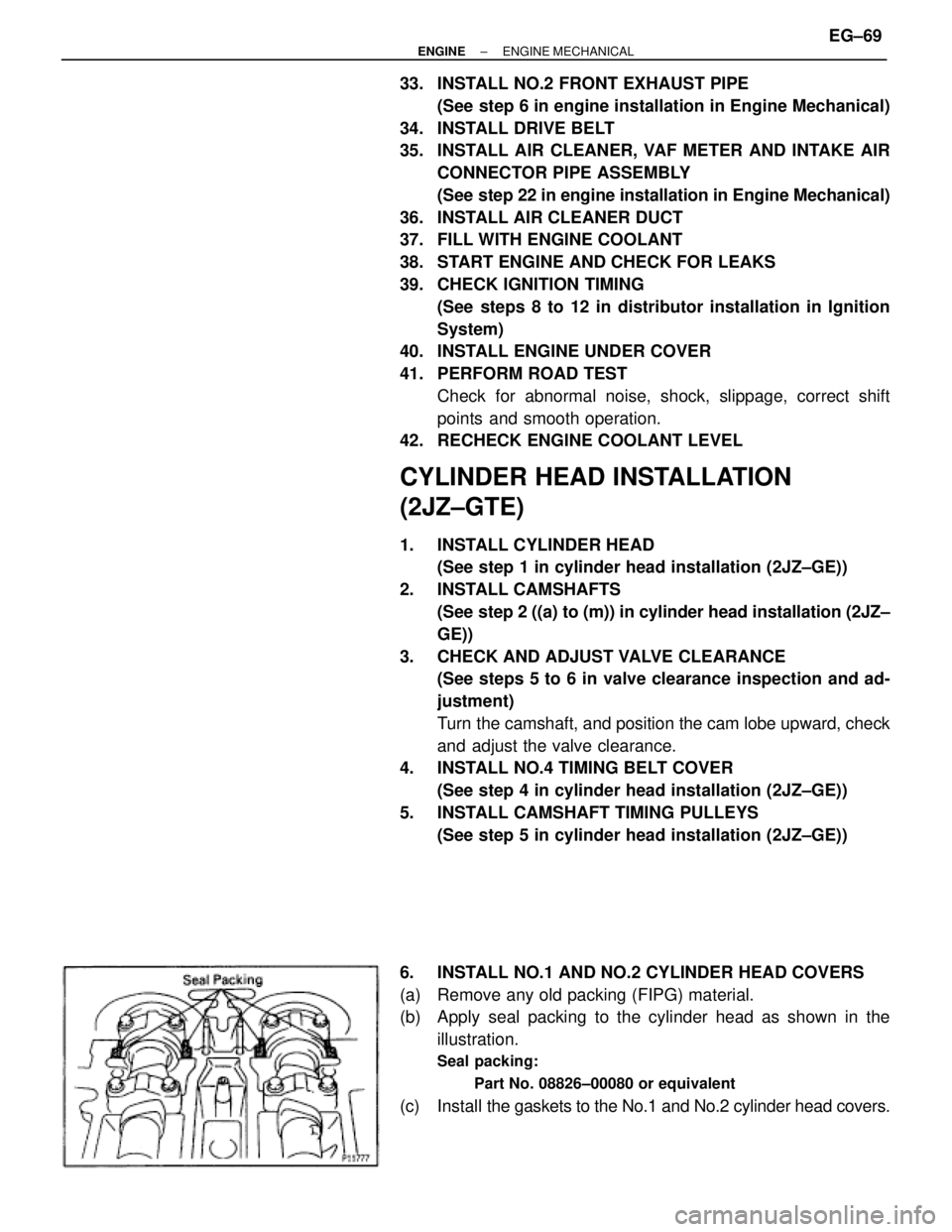
6. INSTALL NO.1 AND NO.2 CYLINDER HEAD COVERS
(a) Remove any old packing (FIPG) material.
(b) Apply seal packing to the cylinder head as shown in the
illustration.
Seal packing:
Part No. 08826±00080 or equivalent
(c) Install the gaskets to the No.1 and No.2 cylinder head covers.
± ENGINEENGINE MECHANICALEG±69
Page 511 of 878

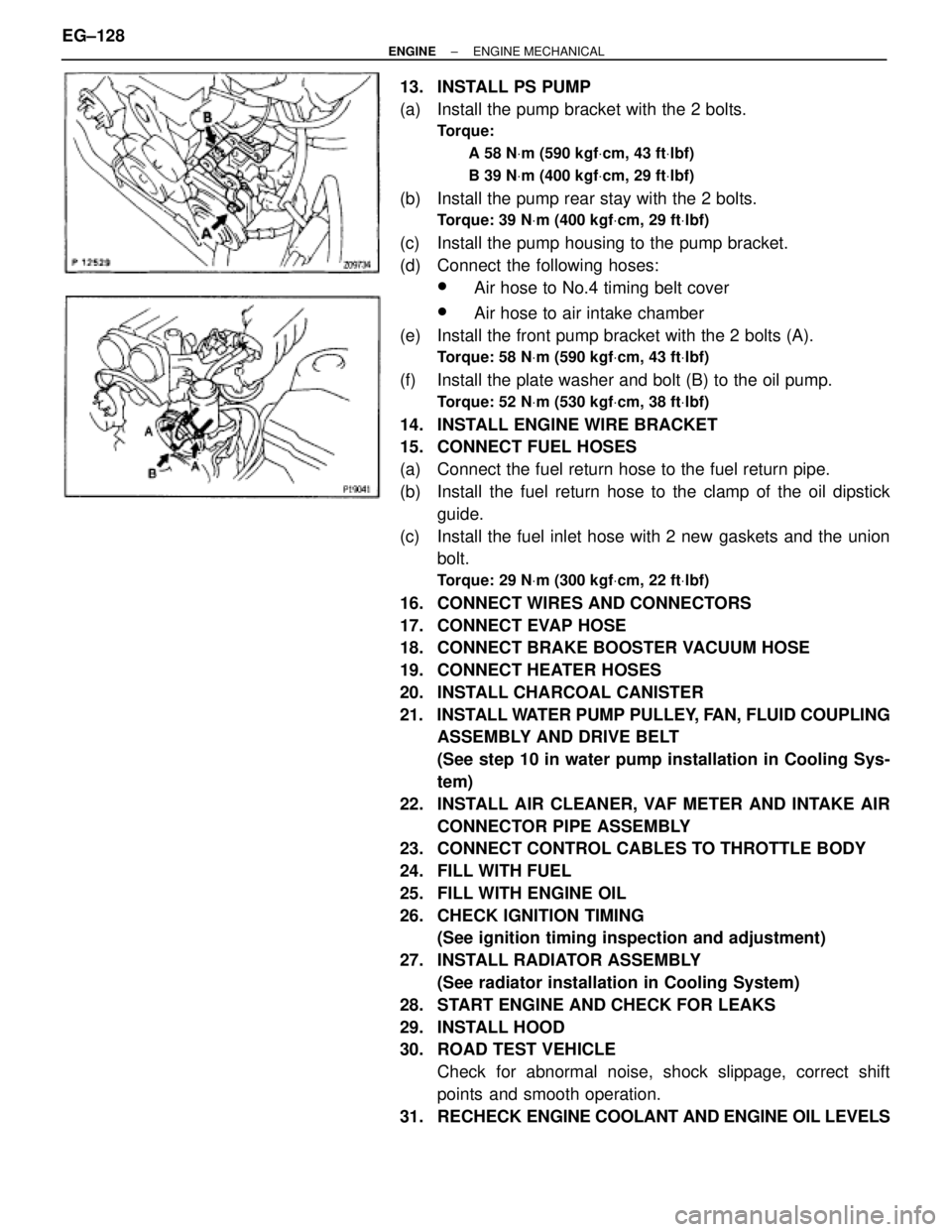
13. INSTALL PS PUMP
(a) Install the pump bracket with the 2 bolts.
Torque:
A 58 NVm (590 kgfVcm, 43 ftVlbf)
B 39 NVm (400 kgfVcm, 29 ftVlbf)
(b) Install the pump rear stay with the 2 bolts.
Torque: 39 NVm (400 kgfVcm, 29 ftVlbf)
(c) Install the pump housing to the pump bracket.
(d) Connect the following hoses:
wAir hose to No.4 timing belt cover
wAir hose to air intake chamber
(e) Install the front pump bracket with the 2 bolts (A).
Torque: 58 NVm (590 kgfVcm, 43 ftVlbf)
(f) Install the plate washer and bolt (B) to the oil pump.
Torque: 52 NVm (530 kgfVcm, 38 ftVlbf)
14. INSTALL ENGINE WIRE BRACKET
15. CONNECT FUEL HOSES
(a) Connect the fuel return hose to the fuel return pipe.
(b) Install the fuel return hose to the clamp of the oil dipstick
guide.
(c) Install the fuel inlet hose with 2 new gaskets and the union
bolt.
Torque: 29 NVm (300 kgfVcm, 22 ftVlbf)
16. CONNECT WIRES AND CONNECTORS
17. CONNECT EVAP HOSE
18. CONNECT BRAKE BOOSTER VACUUM HOSE
19. CONNECT HEATER HOSES
20. INSTALL CHARCOAL CANISTER
21. INSTALL WATER PUMP PULLEY, FAN, FLUID COUPLING
ASSEMBLY AND DRIVE BELT
(See step 10 in water pump installation in Cooling Sys-
tem)
22. INSTALL AIR CLEANER, VAF METER AND INTAKE AIR
CONNECTOR PIPE ASSEMBLY
23. CONNECT CONTROL CABLES TO THROTTLE BODY
24. FILL WITH FUEL
25. FILL WITH ENGINE OIL
26. CHECK IGNITION TIMING
(See ignition timing inspection and adjustment)
27. INSTALL RADIATOR ASSEMBLY
(See radiator installation in Cooling System)
28. START ENGINE AND CHECK FOR LEAKS
29. INSTALL HOOD
30. ROAD TEST VEHICLE
Check for abnormal noise, shock slippage, correct shift
points and smooth operation.
31. RECHECK ENGINE COOLANT AND ENGINE OIL LEVELS EG±128
± ENGINEENGINE MECHANICAL
Page 515 of 878
31. CHECK IGNITION TIMING
(See ignition timing inspection)
32. INSTALL RADIATOR ASSEMBLY
(See radiator installation in Cooling System)
33. INSTALL HOOD
34. ROAD TEST VEHICLE
Check for abnormal noise, shock slippage, correct shift
points and smooth operation.
35. RECHECK ENGINE COOLANT AND ENGINE OIL LEVELS EG±132
± ENGINEENGINE MECHANICAL
Page 542 of 878

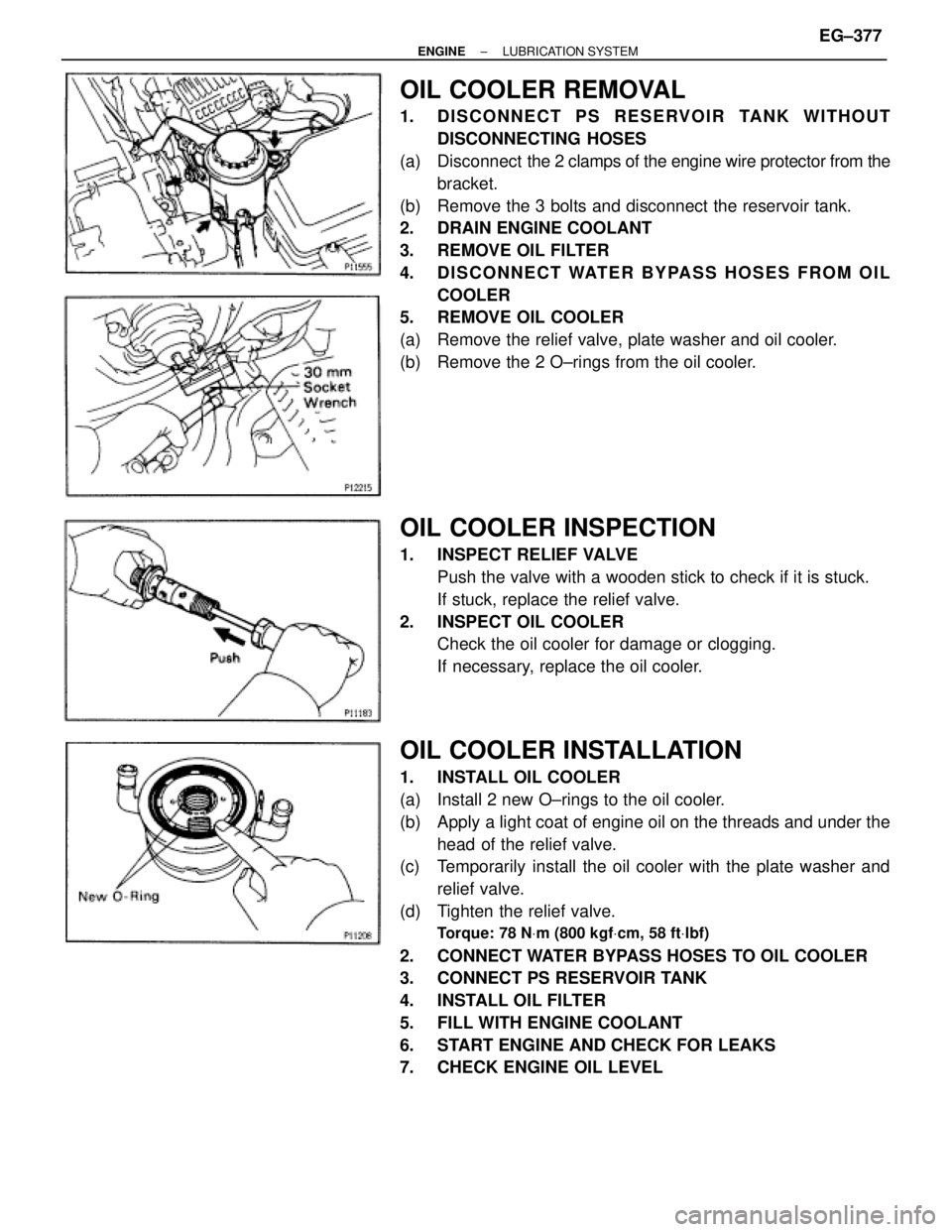
OIL COOLER REMOVAL
1. DISCONNECT PS RESERVOIR TANK WITHOUT
DISCONNECTING HOSES
(a) Disconnect the 2 clamps of the engine wire protector from the
bracket.
(b) Remove the 3 bolts and disconnect the reservoir tank.
2. DRAIN ENGINE COOLANT
3. REMOVE OIL FILTER
4. DISCONNECT WATER BYPASS HOSES FROM OIL
COOLER
5. REMOVE OIL COOLER
(a) Remove the relief valve, plate washer and oil cooler.
(b) Remove the 2 O±rings from the oil cooler.
OIL COOLER INSPECTION
1. INSPECT RELIEF VALVE
Push the valve with a wooden stick to check if it is stuck.
If stuck, replace the relief valve.
2. INSPECT OIL COOLER
Check the oil cooler for damage or clogging.
If necessary, replace the oil cooler.
OIL COOLER INSTALLATION
1. INSTALL OIL COOLER
(a) Install 2 new O±rings to the oil cooler.
(b) Apply a light coat of engine oil on the threads and under the
head of the relief valve.
(c) Temporarily install the oil cooler with the plate washer and
relief valve.
(d) Tighten the relief valve.
Torque: 78 NVm (800 kgfVcm, 58 ftVlbf)
2. CONNECT WATER BYPASS HOSES TO OIL COOLER
3. CONNECT PS RESERVOIR TANK
4. INSTALL OIL FILTER
5. FILL WITH ENGINE COOLANT
6. START ENGINE AND CHECK FOR LEAKS
7. CHECK ENGINE OIL LEVEL
± ENGINELUBRICATION SYSTEMEG±377
Page 573 of 878
COOLANT CHECK
1. CHECK ENGINE COOLANT LEVEL AT RADIATOR
RESERVOIR
The engine coolant level should be between the ºLOWº and
ºFULLº lines.
If low, check for leaks and add engine coolant up to the
ºFULLº line.
2. CHECK ENGINE COOLANT QUALITY
(a) Remove the radiator cap.
CAUTION: To avoid the danger of being burned, do not remove
the radiator cap while the engine and radiator are still hot, as
fluid and steam can be blown out under pressure.
(b) There should not be any excessive deposits of rust or scale
around the radiator cap or radiator filler hole, and the coolant
should be free from oil.
If excessively dirty, replace the coolant.
(c) Reinstall the radiator cap. EG±330
± ENGINECOOLING SYSTEM
Page 589 of 878
RADIATOR REMOVAL
Installation is in the reverse order of removal.
1. REMOVE ENGINE UNDER COVER
INSTALLATION HINT: Start the engine, and check for cool-
ant and A/T fluid leaks.
2. REMOVE BATTERY AND BATTERY TRAY
3. DRAIN ENGINE COOLANT
4. 2JZ±GTE:
REMOVE NO.2 AIR TUBE
5. REMOVE NO.2 FAN SHROUD
(a) Remove the 2 clips.
(b) Disconnect the claw of the No.2 fan shroud from the hook of
the No.1 fan shroud, and remove the No.2 fan shroud.
6. REMOVE AIR CLEANER DUCT
7. 2JZ±GTE:
REMOVE NO.5 AIR HOSE
8. REMOVE LH HEADLIGHT BEAM ANGLE GAUGE
Remove the screw and beam angle gauge.
9. DISCONNECT HOSES FROM RADIATOR
Disconnect these hoses from the radiator:
(1) Reservoir inlet hose
(2) Upper radiator hose
(3) Lower radiator hose
(4) A/T:
2 oil cooler hoses
Plug the hose ends.
INSTALLATION HINT: Check the A/T fluid level.
(See item 21 in Maintenance) EG±346
± ENGINECOOLING SYSTEM
Page 626 of 878
![TOYOTA SUPRA 1986 Service Repair Manual 24
ELECTRICAL WIRING ROUTING
Position of Parts in Engine Compartment
[2JZ±GTE]
A 1 A/C Ambient Temp. Sensor E 4 Engine Coolant Temp. Sender (Water Temp. Sender)
A 2 A/C Condenser Fan Motor E 5 Engine TOYOTA SUPRA 1986 Service Repair Manual 24
ELECTRICAL WIRING ROUTING
Position of Parts in Engine Compartment
[2JZ±GTE]
A 1 A/C Ambient Temp. Sensor E 4 Engine Coolant Temp. Sender (Water Temp. Sender)
A 2 A/C Condenser Fan Motor E 5 Engine](/manual-img/14/57467/w960_57467-625.png)
24
ELECTRICAL WIRING ROUTING
Position of Parts in Engine Compartment
[2JZ±GTE]
A 1 A/C Ambient Temp. Sensor E 4 Engine Coolant Temp. Sender (Water Temp. Sender)
A 2 A/C Condenser Fan Motor E 5 Engine Coolant Temp. SW (Water Temp. SW)
A 3 A/C Triple Pressure SW E 6 Engine Hood Courtesy SW
(A/C Dual and Single Pressure SW) E 7 Engine Oil Level Sensor
A 4 A/C Magnetic Clutch and Lock Sensor
A 5 A/T Fluid Temp. Sensor F 1 Front Airbag Sensor LH
A 6 ABS Actuator F 2 Front Airbag Sensor RH
A 7 ABS Actuator F 3 Front Fog Light and Parking Light LH
A 10 ABS Speed Sensor Front LH F 4 Front Fog Light and Parking Light RH
A 11 ABS Speed Sensor Front RH F 5 Front Side Marker Light LH
F 6 Front Side Marker Light RH
B 1 Back±Up Light SW (for M/T) F 7 Front Turn Signal Light LH
B 2 Brake Fluid Level Warning SW F 8 Front Turn Signal Light RH
F 9 Front Wiper Motor
C 1 Camshaft Position Sensor No. 1
C 2 Camshaft Position Sensor No. 2 G 1 Generator (Alternator)
C 3 Crankshaft Position Sensor G 2 Generator (Alternator)
C 4 Cruise Control Actuator
H 1 Headlight Hi LH
D 1 Data Link Connector 1 (Check Connector) H 2 Headlight Hi RH
D 2 Daytime Running Light Relay No. 3 H 3 Headlight Lo LH
D 3 Daytime Running Light Relay No. 3 H 4 Headlight Lo RH
H 5 Heated Oxygen Sensor (Main)
E 1 EGR Gas Temp. Sensor H 8 Horn LH
E 2 Electronically Controlled Transmission Solenoid H 9 Horn RH
E 3 Engine Coolant Temp. Sensor (EFI Water Temp. Sensor)
Page 628 of 878
![TOYOTA SUPRA 1986 Service Repair Manual 26
ELECTRICAL WIRING ROUTING
Position of Parts in Engine Compartment
[2JZ±GE]
A 1 A/C Ambient Temp. Sensor E 2 Electronically Controlled Transmission Solenoid
A 3 A/C Dual Pressure SW E 3 Engine Cool TOYOTA SUPRA 1986 Service Repair Manual 26
ELECTRICAL WIRING ROUTING
Position of Parts in Engine Compartment
[2JZ±GE]
A 1 A/C Ambient Temp. Sensor E 2 Electronically Controlled Transmission Solenoid
A 3 A/C Dual Pressure SW E 3 Engine Cool](/manual-img/14/57467/w960_57467-627.png)
26
ELECTRICAL WIRING ROUTING
Position of Parts in Engine Compartment
[2JZ±GE]
A 1 A/C Ambient Temp. Sensor E 2 Electronically Controlled Transmission Solenoid
A 3 A/C Dual Pressure SW E 3 Engine Coolant Temp. Sensor (EFI Water Temp.
A 4 A/C Magnetic Clutch and Lock Sensor Sensor)
A 5 A/T Fluid Temp. Sensor E 4 Engine Coolant Temp. Sender (Water Temp.
A 6 ABS Actuator Sender)
A 7 ABS Actuator E 6 Engine Hood Courtesy SW
A 8 ABS Relay E 7 Engine Oil Level Sensor
A 9 ABS Relay
A 10 ABS Speed Sensor Front LH F 1 Front Airbag Sensor LH
A 11 ABS Speed Sensor Front RH F 2 Front Airbag Sensor RH
F 3 Front Fog Light and Parking Light LH
B 1 Back-Up Light SW (for M/T) F 4 Front Fog Light and Parking Light RH
B 2 Brake Fluid Level Warning SW F 5 Front Side Marker Light LH
F 6 Front Side Marker Light RH
C 4 Cruise Control Actuator F 7 Front Turn Signal Light LH
F 8 Front Turn Signal Light RH
D 1 Data Link Connector 1 (Check Connector) F 9 Front Wiper Motor
D 4 Distributor
G 1 Generator (Alternator)
E 1 EGR Gas Temp. Sensor G 2 Generator (Alternator)