1986 TOYOTA SUPRA cooling
[x] Cancel search: coolingPage 407 of 878
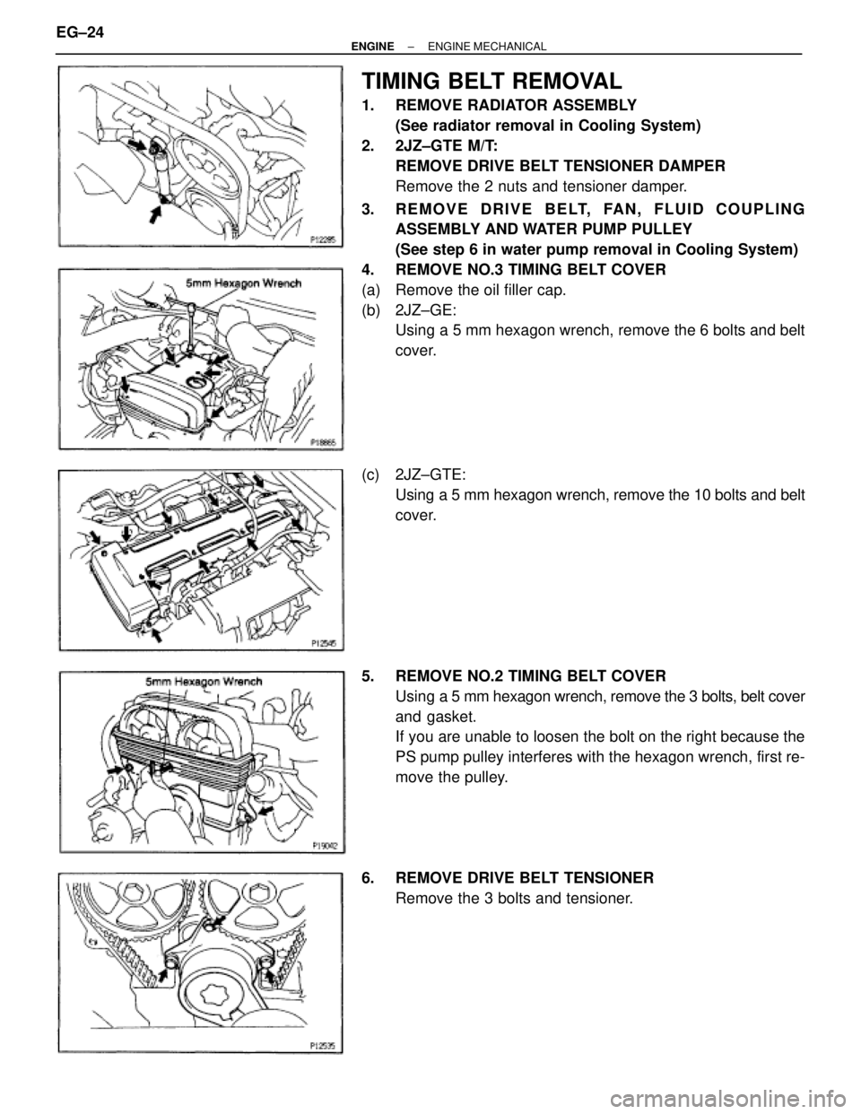
TIMING BELT REMOVAL
1. REMOVE RADIATOR ASSEMBLY
(See radiator removal in Cooling System)
2. 2JZ±GTE M/T:
REMOVE DRIVE BELT TENSIONER DAMPER
Remove the 2 nuts and tensioner damper.
3. REMOVE DRIVE BELT, FAN, FLUID COUPLING
ASSEMBLY AND WATER PUMP PULLEY
(See step 6 in water pump removal in Cooling System)
4. REMOVE NO.3 TIMING BELT COVER
(a) Remove the oil filler cap.
(b) 2JZ±GE:
Using a 5 mm hexagon wrench, remove the 6 bolts and belt
cover.
(c) 2JZ±GTE:
Using a 5 mm hexagon wrench, remove the 10 bolts and belt
cover.
5. REMOVE NO.2 TIMING BELT COVER
Using a 5 mm hexagon wrench, remove the 3 bolts, belt cover
and gasket.
If you are unable to loosen the bolt on the right because the
PS pump pulley interferes with the hexagon wrench, first re-
move the pulley.
6. REMOVE DRIVE BELT TENSIONER
Remove the 3 bolts and tensioner. EG±24
± ENGINEENGINE MECHANICAL
Page 416 of 878
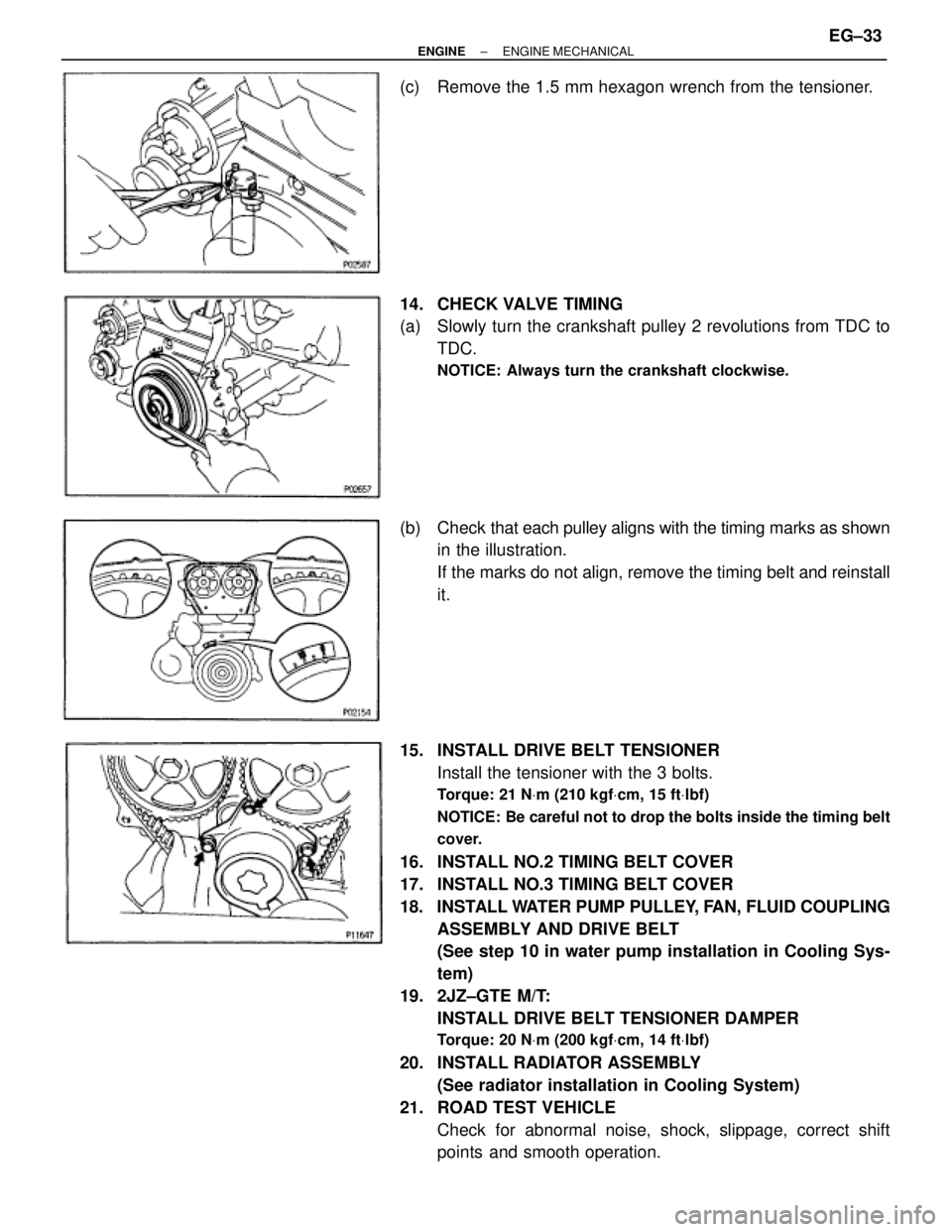
(c) Remove the 1.5 mm hexagon wrench from the tensioner.
14. CHECK VALVE TIMING
(a) Slowly turn the crankshaft pulley 2 revolutions from TDC to
TDC.
NOTICE: Always turn the crankshaft clockwise.
(b) Check that each pulley aligns with the timing marks as shown
in the illustration.
If the marks do not align, remove the timing belt and reinstall
it.
15. INSTALL DRIVE BELT TENSIONER
Install the tensioner with the 3 bolts.
Torque: 21 NVm (210 kgfVcm, 15 ftVlbf)
NOTICE: Be careful not to drop the bolts inside the timing belt
cover.
16. INSTALL NO.2 TIMING BELT COVER
17. INSTALL NO.3 TIMING BELT COVER
18. INSTALL WATER PUMP PULLEY, FAN, FLUID COUPLING
ASSEMBLY AND DRIVE BELT
(See step 10 in water pump installation in Cooling Sys-
tem)
19. 2JZ±GTE M/T:
INSTALL DRIVE BELT TENSIONER DAMPER
Torque: 20 NVm (200 kgfVcm, 14 ftVlbf)
20. INSTALL RADIATOR ASSEMBLY
(See radiator installation in Cooling System)
21. ROAD TEST VEHICLE
Check for abnormal noise, shock, slippage, correct shift
points and smooth operation.
± ENGINEENGINE MECHANICALEG±33
Page 425 of 878
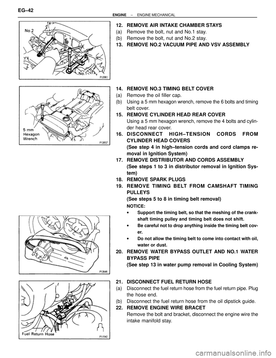
12. REMOVE AIR INTAKE CHAMBER STAYS
(a) Remove the bolt, nut and No.1 stay.
(b) Remove the bolt, nut and No.2 stay.
13. REMOVE NO.2 VACUUM PIPE AND VSV ASSEMBLY
14. REMOVE NO.3 TIMING BELT COVER
(a) Remove the oil filler cap.
(b) Using a 5 mm hexagon wrench, remove the 6 bolts and timing
belt cover.
15. REMOVE CYLINDER HEAD REAR COVER
Using a 5 mm hexagon wrench, remove the 4 bolts and cylin-
der head rear cover.
16. D I S C O N N E C T H I G H ± T E N S I O N C O R D S F R O M
CYLINDER HEAD COVERS
(See step 4 in high±tension cords and cord clamps re-
moval in Ignition System)
17. REMOVE DISTRIBUTOR AND CORDS ASSEMBLY
(See steps 1 to 3 in distributor removal in Ignition Sys-
tem)
18. REMOVE SPARK PLUGS
19. RE MO V E TIMING BE LT FRO M CAMS HAFT TIMING
PULLEYS
(See steps 5 to 8 in timing belt removal)
NOTICE:
wSupport the timing belt, so that the meshing of the crank-
shaft timing pulley and timing belt does not shift.
wBe careful not to drop anything inside the timing belt cov-
er.
wDo not allow the timing belt to come into contact with oil,
water or dust.
20. REMOVE WATER BYPASS OUTLET AND NO.1 WATER
BYPASS PIPE
(See step 13 in water pump removal in Cooling System)
21. DISCONNECT FUEL RETURN HOSE
(a) Disconnect the fuel return hose from the fuel return pipe. Plug
the hose end.
(b) Disconnect the fuel return hose from the oil dipstick guide.
22. REMOVE ENGINE WIRE BRACET
Remove the bolt and bracket, disconnect the engine wire the
intake manifold stay. EG±42
± ENGINEENGINE MECHANICAL
Page 451 of 878
19. INSTALL WATER BYPASS OUTLET AND NO.1 WATER
BYPASS PIPE
(See step 3 in water pump installation in Cooling System)
20. INSTALL TIMING BELT
(See steps 11 to 17 in timing belt removal)
21. INSTALL SPARK PLUGS
22. INSTALL DISTRIBUTOR AND CORDS ASSEMBLY
(See steps 2, 3 and 5 in distributor installation in Ignition
System)
23. CONNECT HIGH±TENSION CORDS TO CYLINDER HEAD
COVERS
(See step 1 in high±tension cords and cord clamps
installation in Ignition System)
24. INSTALL NO.3 TIMING BELT COVER
25. INSTALL CYLINDER HEAD REAR COVER
26. INSTALL NO.2 VACUUM PIPE AND VSV ASSEMBLY
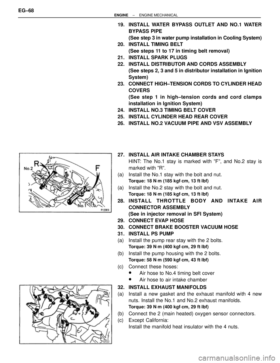
27. INSTALL AIR INTAKE CHAMBER STAYS
HINT: The No.1 stay is marked with ºFº, and No.2 stay is
marked with ºRº.
(a) Install the No.1 stay with the bolt and nut.
Torque: 18 NVm (185 kgfVcm, 13 ftVlbf)
(a) Install the No.2 stay with the bolt and nut.
Torque: 18 NVm (185 kgfVcm, 13 ftVlbf)
28. I N S TA L L T H R OTTLE BODY AND INTAKE AIR
CONNECTOR ASSEMBLY
(See in injector removal in SFI System)
29. CONNECT EVAP HOSE
30. CONNECT BRAKE BOOSTER VACUUM HOSE
31. INSTALL PS PUMP
(a) Install the pump rear stay with the 2 bolts.
Torque: 39 NVm (400 kgfVcm, 29 ftVlbf)
(b) Install the pump housing with the 2 bolts.
Torque: 58 NVm (590 kgfVcm, 43 ftVlbf)
(c) Connect these hoses:
wAir hose to No.4 timing belt cover
wAir hose to air intake chamber
32. INSTALL EXHAUST MANIFOLDS
(a) Install a new gasket and the exhaust manifold with 4 new
nuts. Install the No.1 and No.2 exhaust manifolds.
Torque: 39 NVm (400 kgfVcm, 29 ftVlbf)
(b) Connect the 2 (main heated) oxygen sensor connectors.
(c) Except California:
Install the manifold heat insulator with the 4 nuts. EG±68
± ENGINEENGINE MECHANICAL
Page 461 of 878
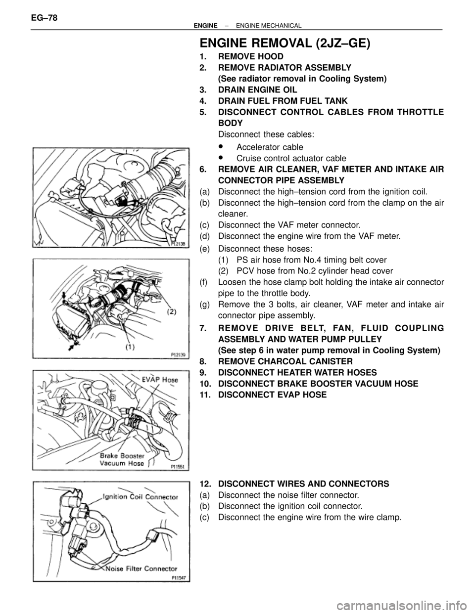
ENGINE REMOVAL (2JZ±GE)
1. REMOVE HOOD
2. REMOVE RADIATOR ASSEMBLY
(See radiator removal in Cooling System)
3. DRAIN ENGINE OIL
4. DRAIN FUEL FROM FUEL TANK
5. DISCONNECT CONTROL CABLES FROM THROTTLE
BODY
Disconnect these cables:
wAccelerator cable
wCruise control actuator cable
6. REMOVE AIR CLEANER, VAF METER AND INTAKE AIR
CONNECTOR PIPE ASSEMBLY
(a) Disconnect the high±tension cord from the ignition coil.
(b) Disconnect the high±tension cord from the clamp on the air
cleaner.
(c) Disconnect the VAF meter connector.
(d) Disconnect the engine wire from the VAF meter.
(e) Disconnect these hoses:
(1) PS air hose from No.4 timing belt cover
(2) PCV hose from No.2 cylinder head cover
(f) Loosen the hose clamp bolt holding the intake air connector
pipe to the throttle body.
(g) Remove the 3 bolts, air cleaner, VAF meter and intake air
connector pipe assembly.
7. REMOVE DRIVE BELT, FAN, FLUID COUPLING
ASSEMBLY AND WATER PUMP PULLEY
(See step 6 in water pump removal in Cooling System)
8. REMOVE CHARCOAL CANISTER
9. DISCONNECT HEATER WATER HOSES
10. DISCONNECT BRAKE BOOSTER VACUUM HOSE
11. DISCONNECT EVAP HOSE
12. DISCONNECT WIRES AND CONNECTORS
(a) Disconnect the noise filter connector.
(b) Disconnect the ignition coil connector.
(c) Disconnect the engine wire from the wire clamp. EG±78
± ENGINEENGINE MECHANICAL
Page 468 of 878
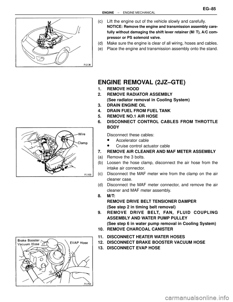
(c) Lift the engine out of the vehicle slowly and carefully.
NOTICE: Remove the engine and transmission assembly care-
fully without damaging the shift lever retainer (M/ T), A/C com-
pressor or PS solenoid valve.
(d) Make sure the engine is clear of all wiring, hoses and cables.
(e) Place the engine and transmission assembly onto the stand.
ENGINE REMOVAL (2JZ±GTE)
1. REMOVE HOOD
2. REMOVE RADIATOR ASSEMBLY
(See radiator removal in Cooling System)
3. DRAIN ENGINE OIL
4. DRAIN FUEL FROM FUEL TANK
5. REMOVE NO.1 AIR HOSE
6. DISCONNECT CONTROL CABLES FROM THROTTLE
BODY
Disconnect these cables:
wAccelerator cable
wCruise control actuator cable
7. REMOVE AIR CLEANER AND MAF METER ASSEMBLY
(a) Remove the 3 bolts.
(b) Loosen the hose clamp, disconnect the air hose from the
intake air connector.
(c) Disconnect the MAF meter wire from the clamp on the air
cleaner case.
(d) Disconnect the MAF meter connector, and remove the air
cleaner and MAF meter assembly.
8. M/T:
REMOVE DRIVE BELT TENSIONER DAMPER
(See step 2 in timing belt removal)
9. REMOVE DRIVE BELT, FAN, FLUID COUPLING
ASSEMBLY AND WATER PUMP PULLEY
(See step 6 in water pump removal in Cooling System)
10. REMOVE CHARCOAL CANISTER
11. DISCONNECT HEATER WATER HOSES
12. DISCONNECT BRAKE BOOSTER VACUUM HOSE
13. DISCONNECT EVAP HOSE
± ENGINEENGINE MECHANICALEG±85
Page 482 of 878
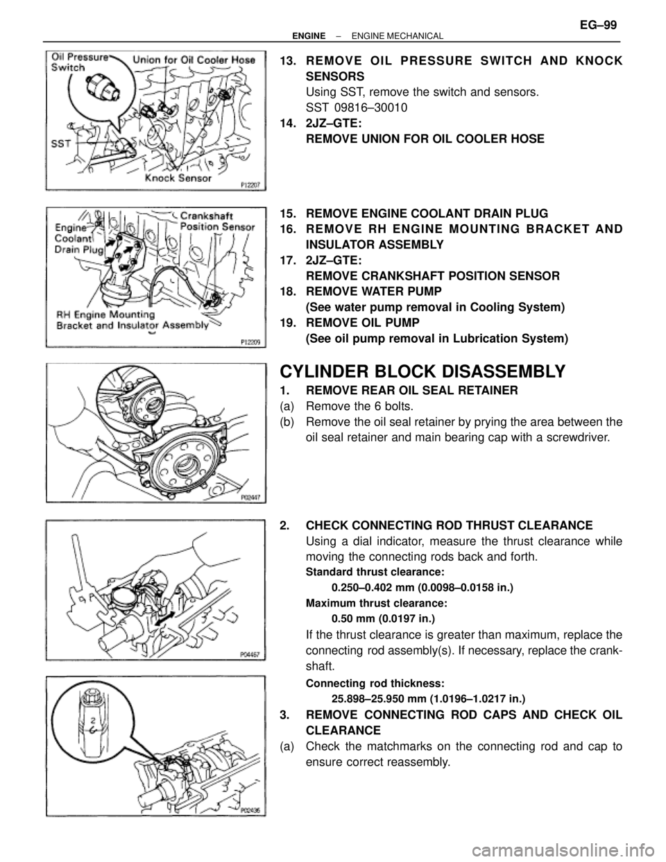
13. REMOVE OIL PRESSURE SWITCH AND KNOCK
SENSORS
Using SST, remove the switch and sensors.
SST 09816±30010
14. 2JZ±GTE:
REMOVE UNION FOR OIL COOLER HOSE
15. REMOVE ENGINE COOLANT DRAIN PLUG
16. R E M O V E R H E N G I N E M O U N T I N G B R A C K E T A N D
INSULATOR ASSEMBLY
17. 2JZ±GTE:
REMOVE CRANKSHAFT POSITION SENSOR
18. REMOVE WATER PUMP
(See water pump removal in Cooling System)
19. REMOVE OIL PUMP
(See oil pump removal in Lubrication System)
CYLINDER BLOCK DISASSEMBLY
1. REMOVE REAR OIL SEAL RETAINER
(a) Remove the 6 bolts.
(b) Remove the oil seal retainer by prying the area between the
oil seal retainer and main bearing cap with a screwdriver.
2. CHECK CONNECTING ROD THRUST CLEARANCE
Using a dial indicator, measure the thrust clearance while
moving the connecting rods back and forth.
Standard thrust clearance:
0.250±0.402 mm (0.0098±0.0158 in.)
Maximum thrust clearance:
0.50 mm (0.0197 in.)
If the thrust clearance is greater than maximum, replace the
connecting rod assembly(s). If necessary, replace the crank-
shaft.
Connecting rod thickness:
25.898±25.950 mm (1.0196±1.0217 in.)
3. REMOVE CONNECTING ROD CAPS AND CHECK OIL
CLEARANCE
(a) Check the matchmarks on the connecting rod and cap to
ensure correct reassembly.
± ENGINEENGINE MECHANICALEG±99
Page 504 of 878
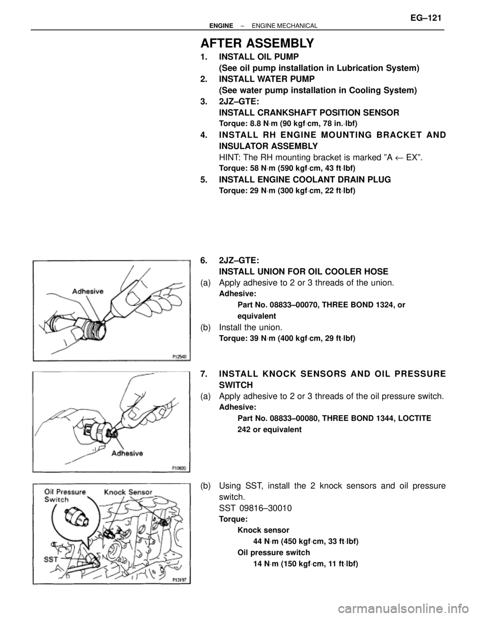
AFTER ASSEMBLY
1. INSTALL OIL PUMP
(See oil pump installation in Lubrication System)
2. INSTALL WATER PUMP
(See water pump installation in Cooling System)
3. 2JZ±GTE:
INSTALL CRANKSHAFT POSITION SENSOR
Torque: 8.8 NVm (90 kgfVcm, 78 in.Vlbf)
4. INSTALL RH ENGINE MOUNTING BRACKET AND
INSULATOR ASSEMBLY
HINT: The RH mounting bracket is marked ºA u EXº.
Torque: 58 NVm (590 kgfVcm, 43 ftVlbf)
5. INSTALL ENGINE COOLANT DRAIN PLUG
Torque: 29 NVm (300 kgfVcm, 22 ftVlbf)
6. 2JZ±GTE:
INSTALL UNION FOR OIL COOLER HOSE
(a) Apply adhesive to 2 or 3 threads of the union.
Adhesive:
Part No. 08833±00070, THREE BOND 1324, or
equivalent
(b) Install the union.
Torque: 39 NVm (400 kgfVcm, 29 ftVlbf)
7. INSTALL KNOCK SENSORS AND OIL PRESSURE
SWITCH
(a) Apply adhesive to 2 or 3 threads of the oil pressure switch.
Adhesive:
Part No. 08833±00080, THREE BOND 1344, LOCTITE
242 or equivalent
(b) Using SST, install the 2 knock sensors and oil pressure
switch.
SST 09816±30010
Torque:
Knock sensor
44 NVm (450 kgfVcm, 33 ftVlbf)
Oil pressure switch
14 NVm (150 kgfVcm, 11 ftVlbf)
± ENGINEENGINE MECHANICALEG±121