Page 30 of 878

DIAGNOSTIC TROUBLE CODE CHECK
USING TOYOTA HAND±HELD TESTER
1. Hook up the TOYOTA hand±held tester to the DLC2.
2. Read the diagnostic trouble codes by following the prompts
on the tester screen.
Please refer to the TOYOTA hand±held tester operation's manual
for further details.
DIAGNOSTIC TROUBLE CODE
CLEARANCE
1. After repair of the trouble areas, the diagnostic trouble code
retained in the ECM memory must be cleared out by
removing the EFI No.1 fuse (30A) from R/B No.2 for 10
seconds or more, with the ignition switch OFF.
HINT:
wCancellation can also be done by removing the negative
(±) terminal cable from the battery, but in this case, other
memory systems (clock, etc.) will also be cancelled out.
wIf it is necessary to work on engine components
requiring removal of the negative (±) terminal cable from
the battery, a check must first be made to see if a
diagnostic trouble code has been recorded.
2. After cancellation, road test the vehicle to check that a normal
code is now read on the malfunction indicator lamp.
If the same diagnostic trouble code appears, it indicates that
the trouble area has not been repaired thoroughly.
ECM DATA MONITOR USING TOYOTA
HAND±HELD TESTER
1. Hook up the TOYOTA hand±held tester to the DLC2.
2. Monitor the ECM data by following the prompts on the tester
screen.
HINT: TOYOTA hand±held tester has a ºSnapshotº function which
records the monitored data.
Please refer to TOYOTA hand±held tester operator's manual for
further details.
ECM TERMINAL VALUES
MEASUREMENT USING TOYOTA
BREAK±OUT±BOX AND TOYOTA
HAND±HELD TESTER
1. Hook up the TOYOTA break±out±box and TOYOTA
handheld tester to the vehicle.
2. Read the ECM input/output values by following the prompts
on the tester screen.
HINT: TOYOTA hand±held tester has a ºSnapshotº function. This
records the measured values and is effective in the diagnosis of
intermittent problems.
Please refer to TOYOTA hand±held tester/TOYOTA break±out±
box operator's manual for further details.
± ENGINE2JZ±GTE ENGINE TROUBLESHOOTINGEG±493
Page 143 of 878

DIAGNOSTIC TROUBLE CODE CHECK
USING TOYOTA HAND±HELD TESTER
1. Hook up the TOYOTA hand±held tester to the DLC2.
2. Read the diagnostic trouble codes by following the prompts
on the tester screen.
Please refer to the TOYOTA hand±held tester operation's
manual for further details.
DIAGNOSTIC TROUBLE CODE CLEARANCE
1. After repair of the trouble areas, the diagnostic trouble code
retained in the ECM memory must be cleared out by
removing the EFI No.1 fuse (30A) from R/B No.2 for 10
seconds or more, with the ignition switch OFF.
HINT:
wCancellation can also be done by removing the negative
(±) terminal cable from the battery, but in this case, other
memory systems (clock, etc.) will also be cancelled out.
wIf it is necessary to work on engine components
requiring removal of the negative (±) terminal cable from
the battery, a check must first be made to see if a
diagnostic trouble code has been recorded.
2. After cancellation, road test the vehicle to check that a normal
code is now read on the malfunction indicator lamp.
If the same diagnostic trouble code appears, it indicates that
the trouble area has not been repaired thoroughly.
ECM DATA MONITOR USING TOYOTA
HAND±HELD TESTER
1. Hook up the TOYOTA hand±held tester to the DLC2.
2. Monitor the ECM data by following the prompts on the tester
screen.
HINT: TOYOTA hand±held tester has a ºSnapshotº function which
records the monitored data.
Please refer to TOYOTA hand±held tester operator's manual for
further details.
ECM TERMINAL VALUES MEASUREMENT
USING TOYOTA BREAK±OUT±BOX AND
TOYOTA HAND±HELD TESTER
1. Hook up the TOYOTA break±out±box and TOYOTA
handheld tester to the vehicle.
2. Read the ECM input/output values by following the prompts
on the tester screen.
HINT: TOYOTA hand±held tester has a ºSnapshotº function. This
records the measured values and is effective in the diagnosis of
intermittent problems.
Please refer to TOYOTA hand±held tester/TOYOTA break±out
box operator's manual for further details.
± ENGINE2JZ±GE ENGINE TROUBLESHOOTINGEG±387
Page 277 of 878
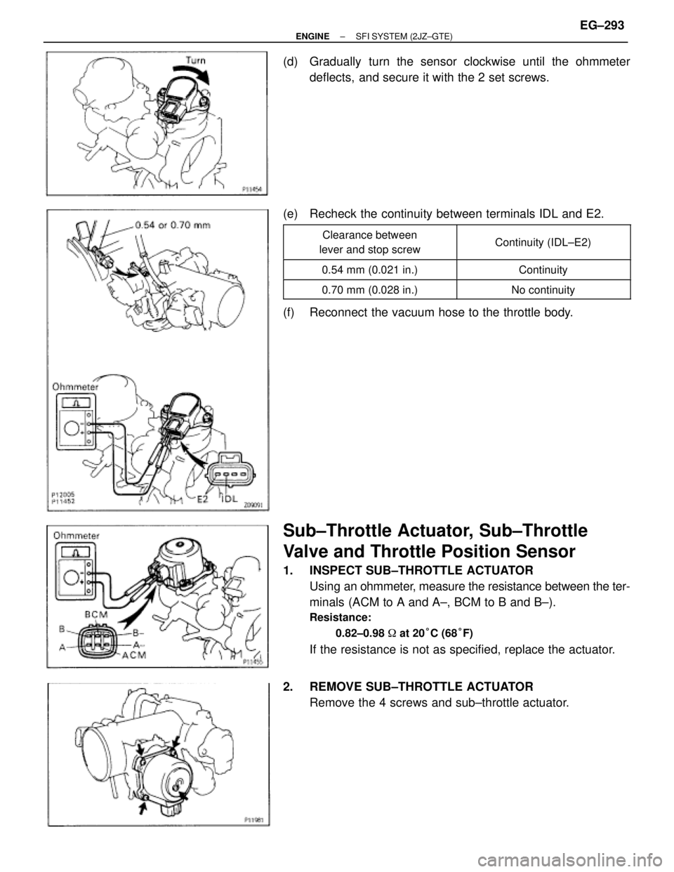
(d) Gradually turn the sensor clockwise until the ohmmeter
deflects, and secure it with the 2 set screws.
(e) Recheck the continuity between terminals IDL and E2.
����������� �
���������� �����������
Clearance between
lever and stop screw������������ �
����������� ������������Continuity (IDL±E2)
����������� �����������0.54 mm (0.021 in.)������������ ������������Continuity
����������� �����������0.70 mm (0.028 in.)������������ ������������No continuity
(f) Reconnect the vacuum hose to the throttle body.
Sub±Throttle Actuator, Sub±Throttle
Valve and Throttle Position Sensor
1. INSPECT SUB±THROTTLE ACTUATOR
Using an ohmmeter, measure the resistance between the ter-
minals (ACM to A and A±, BCM to B and B±).
Resistance:
0.82±0.98 � at 20°C (68°F)
If the resistance is not as specified, replace the actuator.
2. REMOVE SUB±THROTTLE ACTUATOR
Remove the 4 screws and sub±throttle actuator.
± ENGINESFI SYSTEM (2JZ±GTE)EG±293
Page 279 of 878
(d) Connect the tester probe of an ohmmeter to the terminals IDL
and E2 of the sensor.
(e) Gradually turn the sensor clockwise until the ohmmeter
deflects, and secure it with the 2 set screws.
(f) Recheck the continuity between terminals IDL and E2.
����������� �
���������� �����������
Clearance between
lever and stop screw������������ �
����������� ������������Continuity (IDL±E2)
����������� �����������0.41 mm (0.016 in.)������������ ������������Continuity
����������� �����������0.48 mm (0.019 in.)������������ ������������No continuity
6. REINSTALL SUB±THROTTLE ACTUATOR
Install the sub±throttle actuator with the 4 screws.
± ENGINESFI SYSTEM (2JZ±GTE)EG±295
Page 336 of 878
INJECTORS INSTALLATION
1. INSTALL INJECTORS AND DELIVERY PIPE
(a) California:
Install new insulator and grommet to each injector.
(b) Except California:
Install a new grommet to each injector.
(c) California:
Apply a light coat of gasoline to 2 new O±rings, and install
them to each injector.
(d) Except California:
Apply a light coat of gasoline to a new O±ring, and install it
to each injector.
(e) While turning the injector clockwise and counterclockwise,
push it to the delivery pipe. Install the 6 injectors.
(f) Position the injector connector outward.
(g) Install these parts to the intake manifold:
(1) 3 spacers
(2) Except California:
6 new insulators
(h) Install the 3 bolts to the delivery pipe.
(i) California:
Apply a light coat of gasoline to O±ring on each injector.
(j) Attach the 6 injectors together with the delivery pipe to the
intake manifold. EG±210
± ENGINESFI SYSTEM (2JZ±GE)
Page 350 of 878
(b) Insert a 0.50 mm (0.020 in.) feeler gauge between the throttle
stop screw and stop lever.
(c) Connect the tester probe of an ohmmeter to the terminals IDL
and E2 of the sensor.
(d) Gradually turn the sensor clockwise until the ohmmeter
deflects, and secure it with the 2 set screws.
(e) Recheck the continuity between terminals IDL and E2.
����������� �
���������� �
���������� �����������
Clearance between
lever and stop screw
������������ �
����������� �
����������� ������������
Continuity (IDL±E2)
����������� �����������0.40 mm (0.016 in.)������������ ������������Continuity
����������� �����������0.60 mm (0.024 in.)������������ ������������No continuity
EG±224± ENGINESFI SYSTEM (2JZ±GE)
Page 394 of 878

HINT: Inspect and adjust the valve clearance when the en-
gine is cold.
1. REMOVE THROTTLE BODY AND INTAKE AIR
CONNECTOR ASSEMBLY
(See steps 1 to 9")
VALVE CLEARANCE INSPECTION AND
ADJUSTMENT (2JZ±GE)
HINT: Inspect and adjust the valve clearance when the en-
gine is cold.
1. REMOVE THROTTLE BODY AND INTAKE AIR
CONNECTOR ASSEMBLY
(See steps 1 to 9 in injector removal in SFI System)
2. DISCONNECT HIGH±TENSION CORDS FROM
CYLINDER HEAD COVERS
(See high±tension cords and cord clamps removal in
Ignition System)
3. REMOVE NO.3, NO.1 AND NO.2 CYLINDER HEAD
COVERS
(a) Remove the 4 bolts, 4 nuts and No.3 cylinder head cover.
(b) Remove the 4 bolts, No.1 cylinder head cover and gasket.
(c) Remove the 4 bolts, No.2 cylinder head cover and gasket.
4. SET NO.1 CYLINDER TO TDC/COMPRESSION
(a) Turn the crankshaft pulley, and align its groove with timing
mark ºOº of the No.1 timing belt cover.
NOTICE: Always turn the crankshaft clockwise.
(b) Check that the timing marks of the camshaft timing pulleys
are aligned with the timing marks of the No.4 timing belt
cover.
If not, turn the crankshaft 1 revolution (360°).
5. INSPECT VALVE CLEARANCE
(a) Check only those valves indicated in the illustration.
wUsing a feeler gauge, measure the clearance between
the valve lifter and camshaft.
wRecord the valve clearance measurements of those that
are out of specification. They will be used later to
determine the required replacement adjusting shim.
± ENGINEENGINE MECHANICALEG±11
Page 408 of 878
7. SET NO.1 CYLINDER TO TDC/COMPRESSION
(a) Turn the crankshaft pulley, and align its groove with timing
mark ºOº of the No.1 timing belt cover.
NOTICE: Always turn the crankshaft clockwise.
(b) Check that the timing marks of the camshaft timing pulleys
are aligned with the timing marks of the No.4 timing belt
cover.
If not, turn the crankshaft 1 revolution (360°).
8. REMOVE TIMING BELT FROM CAMSHAFT TIMING
PULLEYS
HINT (Re±using timing belt): Place matchmarks on the timing
belt and camshaft timing pulleys as shown in the illustration.
(a) Alternately loosen the 2 bolts, and remove them, the
tensioner and dust boot.
(b) Disconnect the timing belt from the camshaft timing pulleys.
± ENGINEENGINE MECHANICALEG±25
 Connect the tester probe of an ohmmeter to the terminals IDL
and E2 of the sensor.
(e) Gradually turn the sensor clockwise until the ohmmeter
deflects, and secure it with the 2 set screws.
(f)")
 California:
Install new insulator and grommet to each injector.
(b) Except California:
Install a new grommet to each injector.
(c) Ca")
 Insert a 0.50 mm (0.020 in.) feeler gauge between the throttle
stop screw and stop lever.
(c) Connect the tester probe of an ohmmeter to the terminals IDL
and E2 of the sensor.
(d) Gradually tur")
 Turn the crankshaft pulley, and align its groove with timing
mark ºOº of the No.1 timing belt cover.
NOTICE: Always turn the crankshaft clockwise.
(b)")