Page 246 of 878

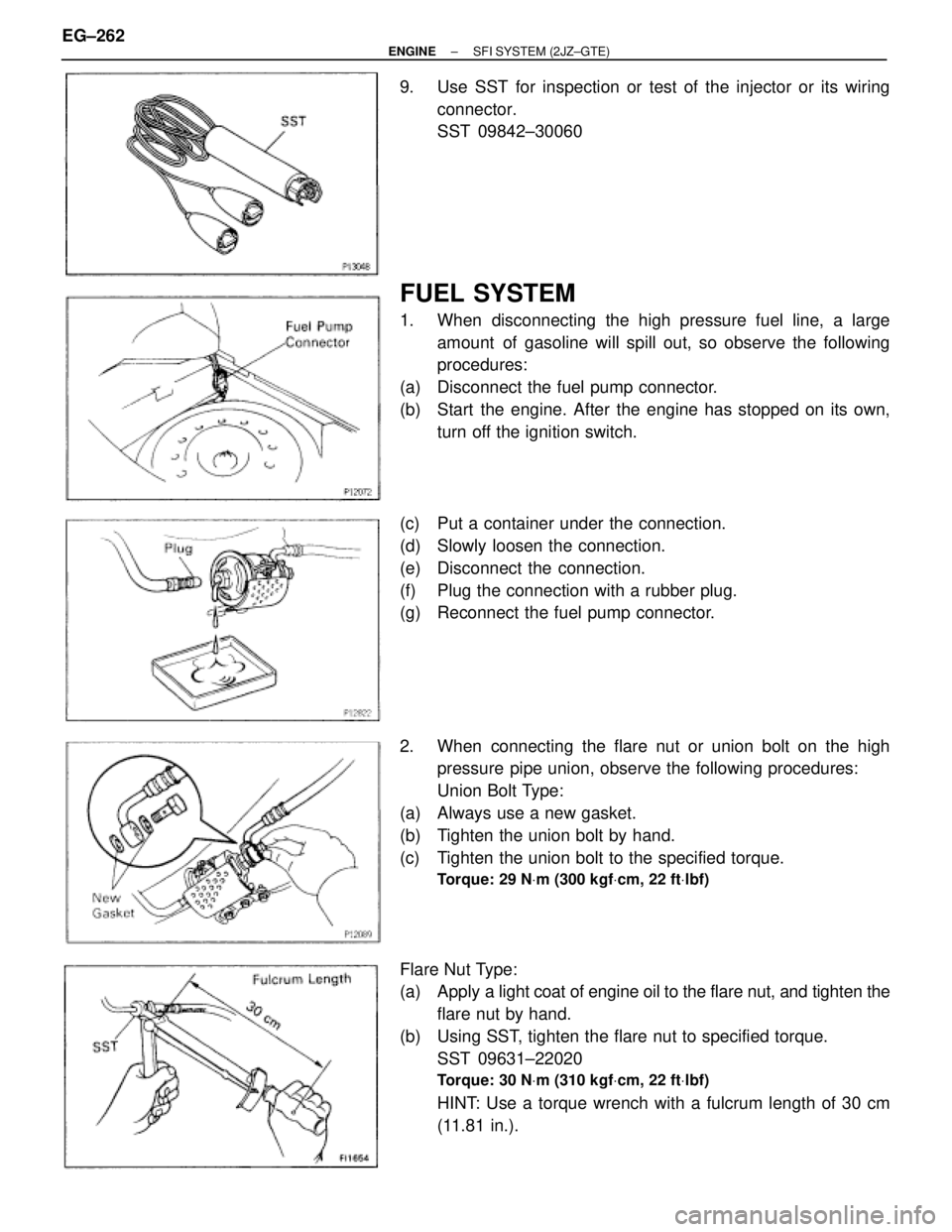
9. Use SST for inspection or test of the injector or its wiring
connector.
SST 09842±30060
FUEL SYSTEM
1. When disconnecting the high pressure fuel line, a large
amount of gasoline will spill out, so observe the following
procedures:
(a) Disconnect the fuel pump connector.
(b) Start the engine. After the engine has stopped on its own,
turn off the ignition switch.
(c) Put a container under the connection.
(d) Slowly loosen the connection.
(e) Disconnect the connection.
(f) Plug the connection with a rubber plug.
(g) Reconnect the fuel pump connector.
2. When connecting the flare nut or union bolt on the high
pressure pipe union, observe the following procedures:
Union Bolt Type:
(a) Always use a new gasket.
(b) Tighten the union bolt by hand.
(c) Tighten the union bolt to the specified torque.
Torque: 29 NVm (300 kgfVcm, 22 ftVlbf)
Flare Nut Type:
(a) Apply a light coat of engine oil to the flare nut, and tighten the
flare nut by hand.
(b) Using SST, tighten the flare nut to specified torque.
SST 09631±22020
Torque: 30 NVm (310 kgfVcm, 22 ftVlbf)
HINT: Use a torque wrench with a fulcrum length of 30 cm
(11.81 in.). EG±262
± ENGINESFI SYSTEM (2JZ±GTE)
Page 317 of 878

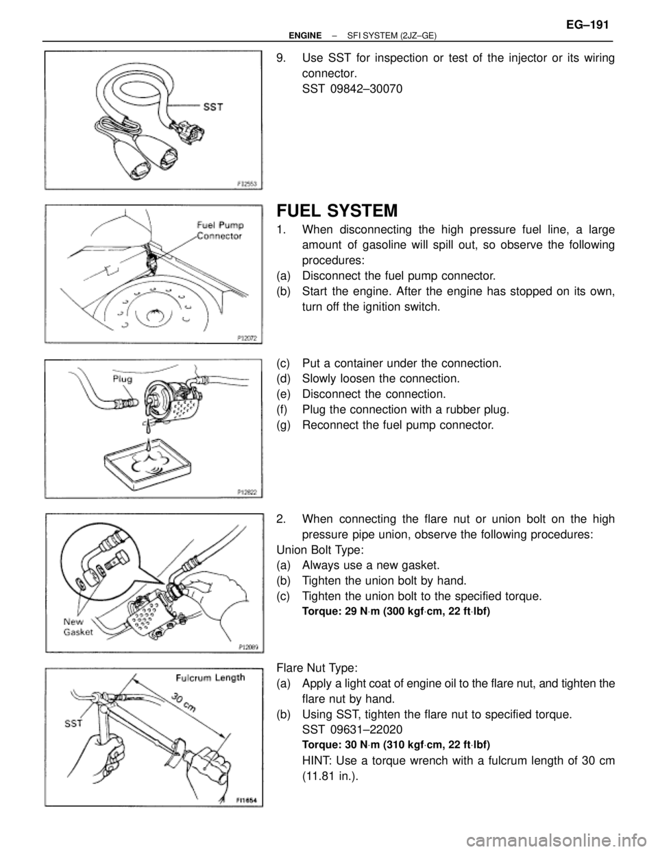
9. Use SST for inspection or test of the injector or its wiring
connector.
SST 09842±30070
FUEL SYSTEM
1. When disconnecting the high pressure fuel line, a large
amount of gasoline will spill out, so observe the following
procedures:
(a) Disconnect the fuel pump connector.
(b) Start the engine. After the engine has stopped on its own,
turn off the ignition switch.
(c) Put a container under the connection.
(d) Slowly loosen the connection.
(e) Disconnect the connection.
(f) Plug the connection with a rubber plug.
(g) Reconnect the fuel pump connector.
2. When connecting the flare nut or union bolt on the high
pressure pipe union, observe the following procedures:
Union Bolt Type:
(a) Always use a new gasket.
(b) Tighten the union bolt by hand.
(c) Tighten the union bolt to the specified torque.
Torque: 29 NVm (300 kgfVcm, 22 ftVlbf)
Flare Nut Type:
(a) Apply a light coat of engine oil to the flare nut, and tighten the
flare nut by hand.
(b) Using SST, tighten the flare nut to specified torque.
SST 09631±22020
Torque: 30 NVm (310 kgfVcm, 22 ftVlbf)
HINT: Use a torque wrench with a fulcrum length of 30 cm
(11.81 in.).
± ENGINESFI SYSTEM (2JZ±GE)EG±191
Page 585 of 878

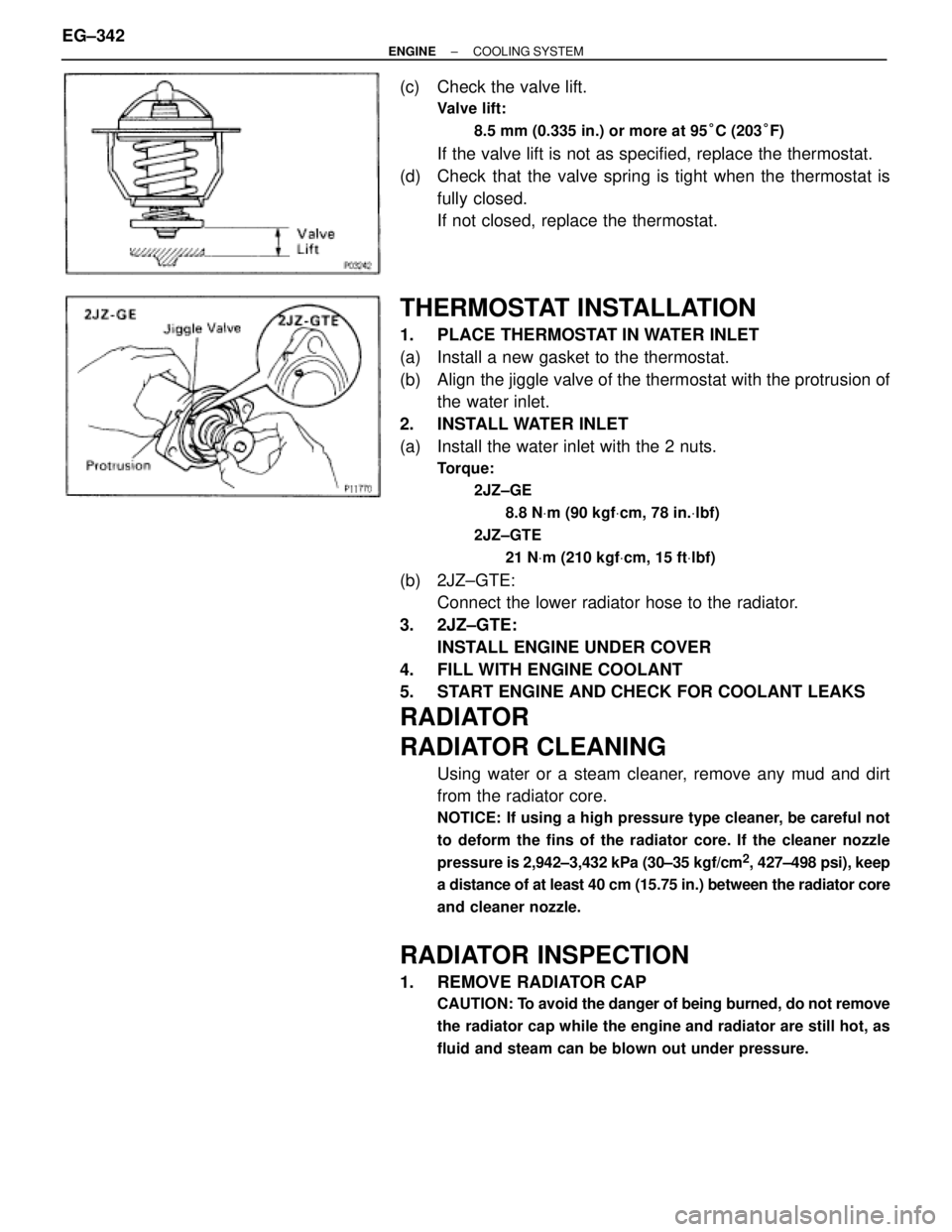
(c) Check the valve lift.
Valve lift:
8.5 mm (0.335 in.) or more at 95°C (203°F)
If the valve lift is not as specified, replace the thermostat.
(d) Check that the valve spring is tight when the thermostat is
fully closed.
If not closed, replace the thermostat.
THERMOSTAT INSTALLATION
1. PLACE THERMOSTAT IN WATER INLET
(a) Install a new gasket to the thermostat.
(b) Align the jiggle valve of the thermostat with the protrusion of
the water inlet.
2. INSTALL WATER INLET
(a) Install the water inlet with the 2 nuts.
Torque:
2JZ±GE
8.8 NVm (90 kgfVcm, 78 in.Vlbf)
2JZ±GTE
21 NVm (210 kgfVcm, 15 ftVlbf)
(b) 2JZ±GTE:
Connect the lower radiator hose to the radiator.
3. 2JZ±GTE:
INSTALL ENGINE UNDER COVER
4. FILL WITH ENGINE COOLANT
5. START ENGINE AND CHECK FOR COOLANT LEAKS
RADIATOR
RADIATOR CLEANING
Using water or a steam cleaner, remove any mud and dirt
from the radiator core.
NOTICE: If using a high pressure type cleaner, be careful not
to deform the fins of the radiator core. If the cleaner nozzle
pressure is 2,942±3,432 kPa (30±35 kgf/cm
2, 427±498 psi), keep
a distance of at least 40 cm (15.75 in.) between the radiator core
and cleaner nozzle.
RADIATOR INSPECTION
1. REMOVE RADIATOR CAP
CAUTION: To avoid the danger of being burned, do not remove
the radiator cap while the engine and radiator are still hot, as
fluid and steam can be blown out under pressure.
EG±342± ENGINECOOLING SYSTEM
Page 616 of 878

15
TROUBLESHOOTING / ABBREVIATIONS
DISCONNECTION AND CONNECTION OF BOLT
TYPE CONNECTORS
For engine control module (engine and electronically controlled
transmission ECU) in this vehicle, connectors are used which
require a bolt built into the connector to be screwed down to
securely connect the connector.
1. Disconnect the connector
After completely loosening the bolt, the two parts of the
connector can be separated.
NOTICE:
Do not pull the wire harness when disconnecting the
connector.
2. Connect the connector
NOTICE:
Before connecting the connector, always check that the
terminals are not bent or damaged.
(a) Match the guide section of the male connector
correctly with the female connector, then press them
together.
(b) Tighten the bolt.
Make sure the connectors are completely connected,
by tightening the bolt until there is a clearance of less
than 1 mm (0.04 in.) between the bottom of male
connector and the end of female connector.
ABBREVIATIONS
The following abbreviations are used in this manual.
ABS = Anti±Lock Brake System O/D = Overdrive
A/C = Air Conditioning PPS = Progressive Power Steering
ACIS = Acoustic Control Induction System R/B = Relay Block
A/T = Automatic Transmission RH = Right±Hand
COMB. = Combination SFI = Sequential Multiport Fuel Injection
ECU = Electronic Control Unit SRS = Supplemental Restraint System
EFI = Electronic Fuel Injection SW = Switch
EGR = Exhaust Gas Recirculation TDCL = Total Diagnostic Communication Link
EVAP = Evaporative Emission TEMP. = Temperature
ISC = Idle Speed Control TRAC = Traction Control System
J/B = Junction Block VSV = Vacuum Switching Valve
LH = Left-Hand w/ = With
M/T = Manual Transmission w/o = Without
* The titles given inside the components are the names of the terminals (terminal codes) and are not treated
as being abbreviations.
Page 617 of 878

15
ABBREVIATIONS
DISCONNECTION AND CONNECTION OF BOLT
TYPE CONNECTORS
For engine control module (engine and electronically controlled
transmission ECU) in this vehicle, connectors are used which
require a bolt built into the connector to be screwed down to
securely connect the connector.
1. Disconnect the connector
After completely loosening the bolt, the two parts of the
connector can be separated.
NOTICE:
Do not pull the wire harness when disconnecting the
connector.
2. Connect the connector
NOTICE:
Before connecting the connector, always check that the
terminals are not bent or damaged.
(a) Match the guide section of the male connector
correctly with the female connector, then press them
together.
(b) Tighten the bolt.
Make sure the connectors are completely connected,
by tightening the bolt until there is a clearance of less
than 1 mm (0.04 in.) between the bottom of male
connector and the end of female connector.
ABBREVIATIONS
The following abbreviations are used in this manual.
ABS = Anti±Lock Brake System O/D = Overdrive
A/C = Air Conditioning PPS = Progressive Power Steering
ACIS = Acoustic Control Induction System R/B = Relay Block
A/T = Automatic Transmission RH = Right±Hand
COMB. = Combination SFI = Sequential Multiport Fuel Injection
ECU = Electronic Control Unit SRS = Supplemental Restraint System
EFI = Electronic Fuel Injection SW = Switch
EGR = Exhaust Gas Recirculation TDCL = Total Diagnostic Communication Link
EVAP = Evaporative Emission TEMP. = Temperature
ISC = Idle Speed Control TRAC = Traction Control System
J/B = Junction Block VSV = Vacuum Switching Valve
LH = Left-Hand w/ = With
M/T = Manual Transmission w/o = Without
* The titles given inside the components are the names of the terminals (terminal codes) and are not treated
as being abbreviations.