Page 4 of 878

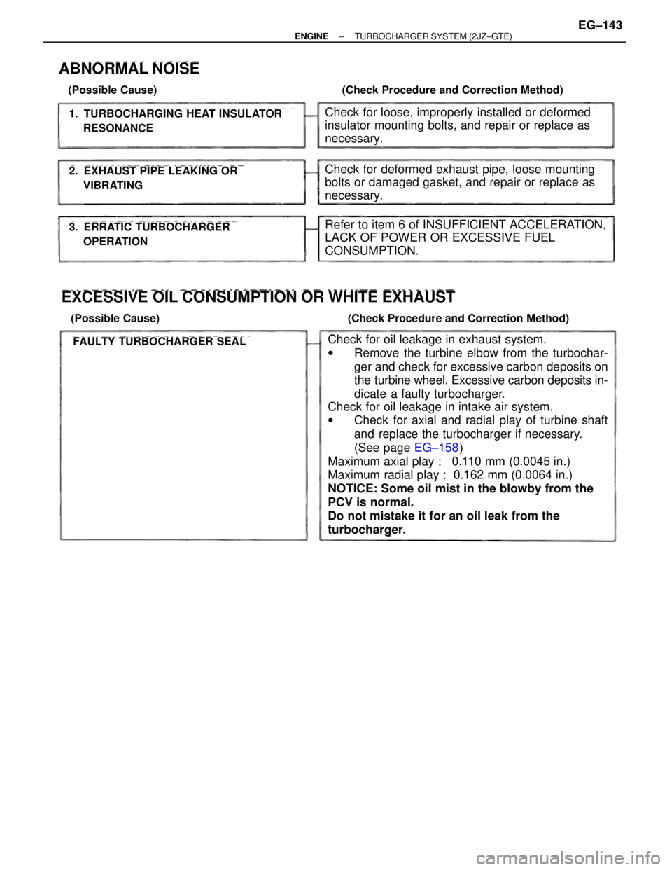
1. TURBOCHARGING HEAT INSULATOR
RESONANCE
2. EXHAUST PIPE LEAKING OR
VIBRATING
3. ERRATIC TURBOCHARGER
OPERATION
ABNORMAL NOISE
(Possible Cause) (Check Procedure and Correction Method)
Check for loose, improperly installed or deformed
insulator mounting bolts, and repair or replace as
necessary.
Check for deformed exhaust pipe, loose mounting
bolts or damaged gasket, and repair or replace as
necessary.
Refer to item 6 of INSUFFICIENT ACCELERATION,
LACK OF POWER OR EXCESSIVE FUEL
CONSUMPTION.
EXCESSIVE OIL CONSUMPTION OR WHITE EXHAUST
(Possible Cause) (Check Procedure and Correction Method)
FAULTY TURBOCHARGER SEALCheck for oil leakage in exhaust system.
wRemove the turbine elbow from the turbochar-
ger and check for excessive carbon deposits on
the turbine wheel. Excessive carbon deposits in-
dicate a faulty turbocharger.
Check for oil leakage in intake air system.
wCheck for axial and radial play of turbine shaft
and replace the turbocharger if necessary.
(See page EG±158)
Maximum axial play : 0.110 mm (0.0045 in.)
Maximum radial play : 0.162 mm (0.0064 in.)
NOTICE: Some oil mist in the blowby from the
PCV is normal.
Do not mistake it for an oil leak from the
turbocharger.
± ENGINETURBOCHARGER SYSTEM (2JZ±GTE)EG±143
Page 478 of 878
6. 2JZ±GTE M/T:
REMOVE CLUTCH COVER SET BOLTS
(a) Remove the 2 bolts and service hole cover.
(b) Place the matchmarks on the flywheel and clutch cover.
(c) Remove the 6 bolts.
7. A/T:
REMOVE TORQUE CONVERTER CLUTCH MOUNTING
BOLTS
(a) Remove the hole plug.
(b) Turn the crankshaft to gain access to each bolt.
Remove the 6 bolts.
8. SEPARATE ENGINE AND TRANSMISSION
Remove the 6 bolts and transmission.
HINT: The º17º is 17 mm head bolt, and º14º is 14 mm head
bolt.
9. 2JZ±GE M/T:
REMOVE CLUTCH COVER AND DISC
(a) Place matchmarks on the flywheel and clutch cover.
(b) Loosen each bolt one turn at a time until spring tension is
released.
(c) Remove the bolts, and pull off the clutch cover with the clutch
disc.
NOTICE: Do not drop the clutch disc.
± ENGINEENGINE MECHANICALEG±95
Page 481 of 878
PREPARATION FOR DISASSEMBLY
1. M/T:
REMOVE FLYWHEEL
2. A/T:
REMOVE DRIVE PLATE
3. INSTALL ENGINE TO ENGINE STAND FOR
DISASSEMBLY
4. REMOVE GENERATOR
5. REMOVE TIMING BELT AND PULLEYS
(See timing belt removal)
6. REMOVE CYLINDER HEAD
(See cylinder head removal)
7. REMOVE OIL FILTER
(See oil and filter replacement in Lubrication System)
8. 2JZ±GTE:
REMOVE OIL COOLER
(See oil cooler removal in Lubrication System)
9. REMOVE NO.2 WATER BYPASS PIPE
(a) 2JZ±GE:
Remove the bolt, 2 nuts, water bypass pipe and gasket.
(b) 2JZ±GTE:
Remove the 2 bolts, 2 nuts, water bypass pipe and gasket.
10. REMOVE OIL FILTER BRACKET
Remove the union bolt, gasket, oil filter bracket and O ±ring.
11. REMOVE LH ENGINE MOUNTING BRACKET AND
INSULATOR ASSEMBLY
12. REMOVE FUEL PIPE SUPPORT EG±98
± ENGINEENGINE MECHANICAL
Page 505 of 878

8. INSTALL FUEL PIPE SUPPORT
Torque: 14 NVm (145 kgfVcm, 10 ftVlbf)
9. INSTALL LH ENGINE MOUNTING BRACKET AND
INSULATOR ASSEMBLY
HINT: LH mounting bracket is marked ºA u INº.
Torque: 58 NVm (590 kgfVcm, 43 ftVlbf)
10. INSTALL OIL FILTER BRACKET
(a) Check and clean the oil filter bracket installation.
(b) Place a new O±ring in position on the oil filter bracket.
(c) Apply clean engine oil to the O±ring.
(d) Install a new gasket to the union bolt.
(e) Install the oil filter braket with the union bolt.
Torque: 88 NVm (900 kgfVcm, 65 ftVlbf)
11. INSTALL NO.2 WATER BYPASS PIPE
(a) Install a new gasket to the water pump.
(b) 2JZ±GE:
Install the water bypass pipe with the bolt and 2 nuts.
Torque: 21 NVm (210 kgfVcm, 15 ftVlbf)
(c) 2JZ±GTE:
Install the water bypass pipe with the 2 bolts and 2 nuts.
Torque: 21 NVm (210 kgfVcm, 15 ftVlbf)
12. 2JZ±GTE:
INSTALL OIL COOLER
(See oil cooler installation in Lubrication System)
13. INSTALL OIL FILTER
(See oil and filter replacement in Lubrication System)
14. INSTALL CYLINDER HEAD
(See cylinder head installation)
15. INSTALL TIMING PULLEYS AND BELT
(See timing belt installation)
16. INSTALL GENERATOR
(See generator installation in Charging System)
17. REMOVE ENGINE STAND FROM ENGINE
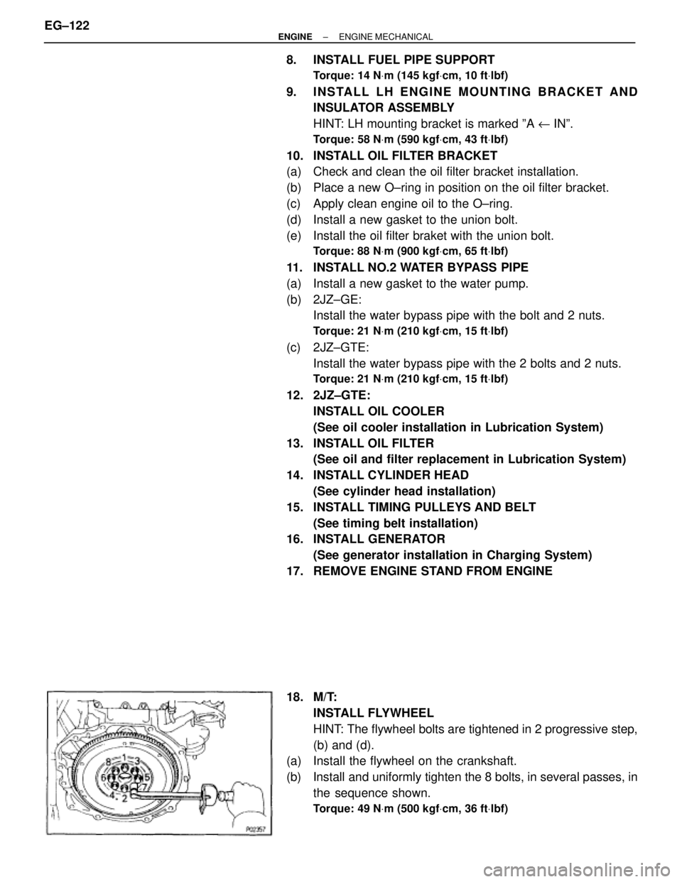
18. M/T:
INSTALL FLYWHEEL
HINT: The flywheel bolts are tightened in 2 progressive step,
(b) and (d).
(a) Install the flywheel on the crankshaft.
(b) Install and uniformly tighten the 8 bolts, in several passes, in
the sequence shown.
Torque: 49 NVm (500 kgfVcm, 36 ftVlbf)
EG±122± ENGINEENGINE MECHANICAL
Page 506 of 878
(c) Mark the flywheel bolt with paint.
(d) Retighten the flywheel bolts by an additional 90°.
(e) Check that the painted mark is now at a 90° angle to (d).
19. A/T:
INSTALL DRIVE PLATE
(a) Install the front spacer, drive plate and rear plate on the
crankshaft.
Adhesive:
Part No. 08833±00070, THREE BOND 1324 or equivalent
(b) Apply adhesive to 2 or 3 threads of the mounting bolt end.
(c) Install and uniformly tighten the 8 bolts, in several passes, in
the sequence shown.
Torque: 83 NVm (850 kgfVcm, 61 ftVlbf)
± ENGINEENGINE MECHANICALEG±123
Page 507 of 878

ENGINE & TRANSMISSION ASSEMBLY
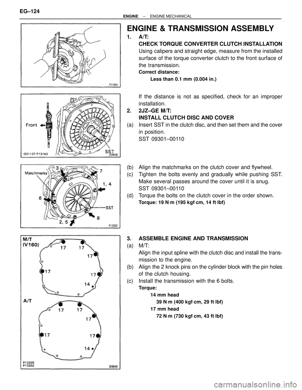
1. A/T:
CHECK TORQUE CONVERTER CLUTCH INSTALLATION
Using calipers and straight edge, measure from the installed
surface of the torque converter clutch to the front surface of
the transmission.
Correct distance:
Less than 0.1 mm (0.004 in.)
If the distance is not as specified, check for an improper
installation.
2. 2JZ±GE M/T:
INSTALL CLUTCH DISC AND COVER
(a) Insert SST in the clutch disc, and then set them and the cover
in position.
SST 09301±00110
(b) Align the matchmarks on the clutch cover and flywheel.
(c) Tighten the bolts evenly and gradually while pushing SST.
Make several passes around the cover until it is snug.
SST 09301±00110
(d) Torque the bolts on the clutch cover in the order shown.
Torque: 19 NVm (195 kgfVcm, 14 ftVlbf)
3. ASSEMBLE ENGINE AND TRANSMISSION
(a) M/T:
Align the input spline with the clutch disc and install the trans-
mission to the engine.
(b) Align the 2 knock pins on the cylinder block with the pin holes
of the clutch housing.
(c) Install the transmission with the 6 bolts.
Torque:
14 mm head
39 NVm (400 kgfVcm, 29 ftVlbf)
17 mm head
72 NVm (730 kgfVcm, 43 ftVlbf)
EG±124± ENGINEENGINE MECHANICAL