Page 5 of 878

TURBOCHARGER
On±Vehicle Inspection
1. INSPECT INTAKE AIR SYSTEM
Check for leakage or clogging between the air cleaner and
turbocharger inlet and between the turbocharger outlet and
cylinder head.
wClogged air cleaner .... Clean or replace air filter
wHoses collapsed or deformed .... Repair or replace
wLeakage from connections .... Check each
connection and repair
wCracks in components Check and replace
2. INSPECT EXHAUST SYSTEM
Check for leakage or clogging between the cylinder head and
turbocharger inlet and between the turbocharger outlet and
exhaust pipe.
wDeformed components Repair or replace
wForeign material in passages Remove
wLeakage from components Repair or replace
wCracks in components Check and replace
3. INSPECT EXHAUST EXHAUST GAS CONTROL VALVE
OPERATION
(a) Disconnect the air hose from the actuator.
(b) Using SST, apply approx. 49 kPa (0.50 kgf/cm
2, 7.1 psi) of
pressure to the actuator.
SST 09992±00241
(c) Check that the actuator push rod moves.
(d) Reconnect the air hose to the actuator.
If operation is not as specified, replace the control valve as-
sembly.
4. INSPECT TURBOCHARGING PRESSURE
(a) Using a 3±way connector, connect SST (turbocharger
pressure gauge) to the hose between the gas filter and turbo
pressure sensor.
SST 09992±00241
(b) While driving with the engine running at 5,600 rpm or more
with the throttle valve fully open in the 1st gear/ L range,
check the turbocharging pressure.
Standard pressure:
61±75 kPa (0.62±0.76 kgf/cm
2, 8.8±10.8 psi)
If the pressure is less than that specified, check the intake
and exhaust systems for leakage. If there is no leakage, re-
place the turbocharger assembly.
If the pressure is above specification, check if the actuator
hose is disconnected or cracked. If not, replace the turbo-
charger assembly. EG±144
± ENGINETURBOCHARGER SYSTEM (2JZ±GTE)
Page 43 of 878

BASIC INSPECTION
In many cases, by carrying out the basic engine check shown in the following flow chart, the location causing
the problem can be found quickly and efficiently. Therefore, use of this check is essential in engine troubleshoot-
ing.
If there is a problem, and a normal code is displayed, proceed to the matrix chart of problem symptoms on page
EG±514. Make sure that every likely cause of the problem is checked.
Is battery positive voltage 11 V or more when engine is stopped?
Is engine cranked?
Does engine start?
Check air filter.
Charge or replace battery.
Proceed to matrix chart of problem symptom
on page EG±514.
Repair or replace.
Remove air filter.
Visually check that the air filter is not excessively
dirty or oily.
If necessary, clean the air filter with compressed
air. First blow from inside thoroughly, then blow
from outside of the air filter.
Charge or replace battery.
Is battery positive voltage 11 V or more when engine is stopped?
EG±506± ENGINE2JZ±GTE ENGINE TROUBLESHOOTING
Page 106 of 878
.
Check for ECM power source circuit (See page
EG±576), and check for open in harness and
connector between terminal +B of data link
connector 1 and main relay.
(1) Turn ignition swi")
(See page IN±30).
Check for ECM power source circuit (See page
EG±576), and check for open in harness and
connector between terminal +B of data link
connector 1 and main relay.
(1) Turn ignition switch ON.
(2) Using SST, connect terminals +B and FP of data
link connector 1.
SST 09843±18020
Check that there is pressure in the hose from the fuel
filter.
Fuel pressure can be felt.
Check fuel pump operation.
Repair or replace harness or connector.
Check for open and short in harness and connector between terminals
+B � +B, FP � FP of the data link connector 1 and fuel pump ECU (See
page IN±30).
Turn ignition switch ON.
Measure voltage between terminal +B of data link con-
nector 1 and body ground.
Voltage: 9 Ð 14 V
Check voltage of terminal +B of data link connector 1.
Check for ECM power source circuit (See
page EG±576), and check for open in harness
and connector between terminal +B of data
link connector 1 and main relay.
INSPECTION PROCEDURE
± ENGINE2JZ±GTE ENGINE TROUBLESHOOTINGEG±569
Page 130 of 878
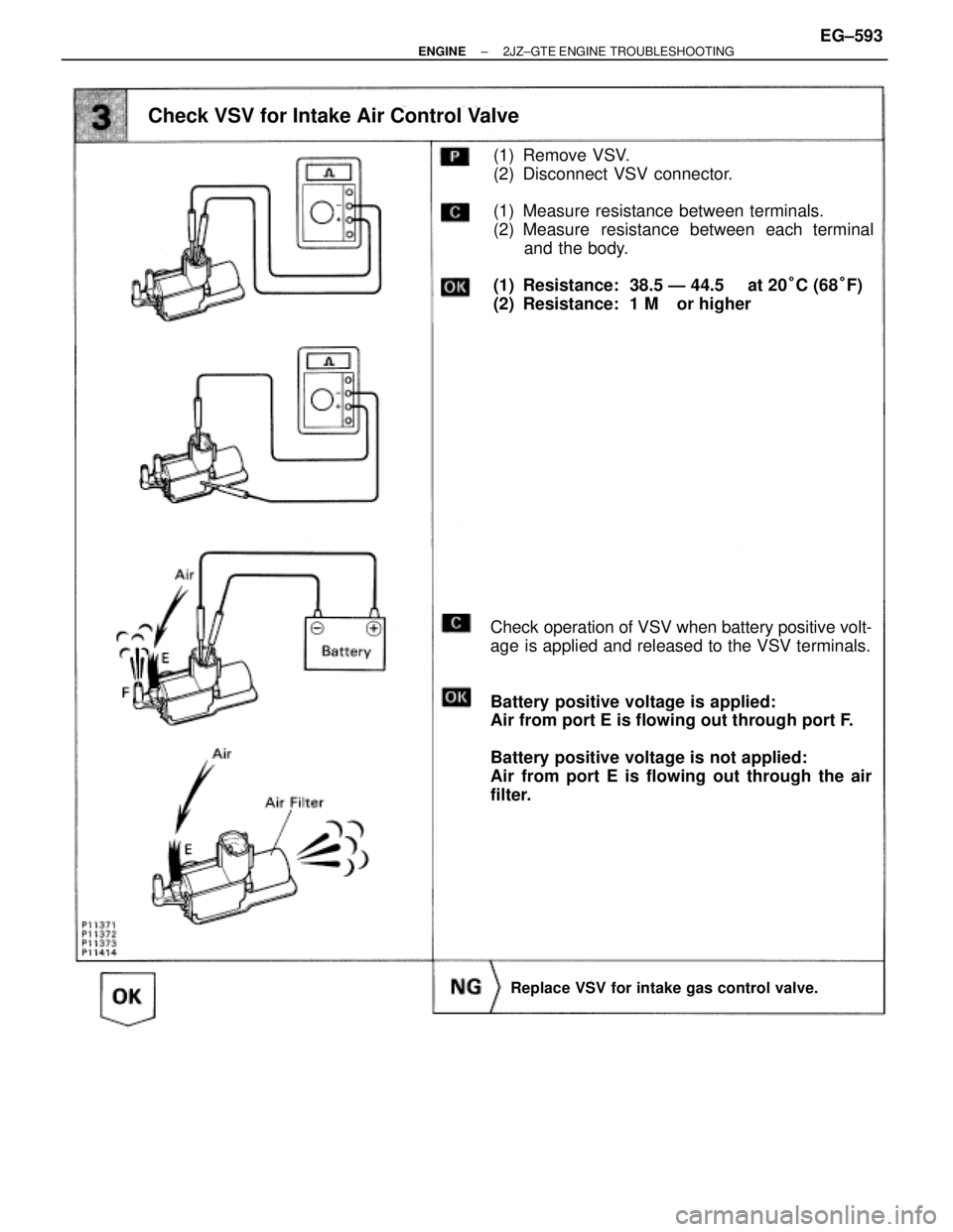
(1) Remove VSV.
(2) Disconnect VSV connector.
(1) Measure resistance between terminals.
(2) Measure resistance between each terminal
and the body.
(1) Resistance: 38.5 Ð 44.5 � at 20°C (68°F)
(2) Resistance: 1 M� or higher
Check operation of VSV when battery positive volt-
age is applied and released to the VSV terminals.
Battery positive voltage is applied:
Air from port E is flowing out through port F.
Battery positive voltage is not applied:
Air from port E is flowing out through the air
filter.
Check VSV for Intake Air Control Valve
Replace VSV for intake gas control valve.
± ENGINE2JZ±GTE ENGINE TROUBLESHOOTINGEG±593
Page 156 of 878
BASIC INSPECTION
In many cases, by carrying out the basic engine check shown in the following flow chart, the location causing
the problem can be found quickly and efficiently. Therefore, use of this check is essential in engine trouble-
shooting.
If there is a problem, and a normal code is displayed, proceed to the matrix chart of problem symptoms on page
EG±408. Make sure that every likely cause of the problem is checked.
EG±408.
Is battery positive voltage 11 V or more when engine is stopped?
Is engine cranked?
Does engine start?
Check air filter.
Charge or replace battery.
Proceed to matrix chart of problem symptoms
on page EG±408.
Repair or replace.
Remove air filter.
Visually check that the air filter is not excessive dirty or
oily.
If necessary, clean the air filter with compressed air. First
blow from inside thoroughly, then blow from outside of
the air filter.
EG±400± ENGINE2JZ±GE ENGINE TROUBLESHOOTING
Page 214 of 878
(1) Turn ignition switch ON.
(2) Using SST, connect terminals +B and FP of
data link connector1.
SST 09843±18020
Check that there is pressure in the hose from the
fuel filter.
Fuel pressure can be felt.
Repair or replace harness or connector.Repair or replace harness or connector.
Check fuel pump operation.
Check for open and short in harness and connector between terminals +B
e +B, FP e FP of the data link connector 1 and fuel pump ECU (See page
IN±30).
Check voltage of terminal +B of data link connector 1.
Turn ignition switch ON.
Measure voltage between terminal +B of data link
connector 1 and body ground.
Fuel pressure can be felt.
Check for ECM power source circuit (See page
EG±465), and check for open in harness and con-
nector between terminal +B of data link connec-
tor 1 and main relay.
INSPECTION PROCEDURE
EG±458± ENGINE2JZ±GE ENGINE TROUBLESHOOTING
Page 235 of 878
INSPECTION PROCEDURE
Check VSV for ACIS.
(1) Remove VSV.
(2) Disconnect VSV connector.
(1) Measure resistance between terminals.
(2) Measure resistance between each terminal
and the body.
(1) Resistance: 38.5 Ð 44.5 � at 20°C (68°F)
(2) Resistance: 1 M� or higher
Check operation of VSV when battery positive
voltage is applied and released to the VSV termi-
nals.
Battery positive voltage is applied:
Air from port E is flowing out through port F.
Battery positive voltage is not applied:
Air from port E is flowing out through the air
filter.
Replace VSV for ACIS.
± ENGINE2JZ±GE ENGINE TROUBLESHOOTINGEG±479
Page 286 of 878
C. Inspect VSV operation
(a) Check that air flows from port E to G.
(b) Apply battery voltage across the terminals.
(c) Check that air flows from port E to the filter.
If operation is not as specified, replace the VSV.
3. REINSTALL VSV
VSV FOR INTAKE AIR CONTROL VALVE
COMPONENTS FOR REMOVAL AND
INSTALLATION
EG±302± ENGINESFI SYSTEM (2JZ±GTE)

 Turn ignition switch ON.
(2) Using SST, connect terminals +B and FP of
data link connector1.
SST 09843±18020
Check that there is pressure in the hose from the
fuel filter.
Fuel pressure can be fe")
 Remove VSV.
(2) Disconnect VSV connector.
(1) Measure resistance between terminals.
(2) Measure resistance between each terminal
and the body.
(1) Resistan")
 Check that air flows from port E to G.
(b) Apply battery voltage across the terminals.
(c) Check that air flows from port E to the filter.
If operation is not as speci")