Page 287 of 878
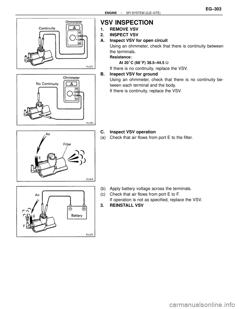
VSV INSPECTION
1. REMOVE VSV
2. INSPECT VSV
A. Inspect VSV for open circuit
Using an ohmmeter, check that there is continuity between
the terminals.
Resistance:
At 20°C (68°F) 38.5±44.5 �
If there is no continuity, replace the VSV.
B. Inspect VSV for ground
Using an ohmmeter, check that there is no continuity be-
tween each terminal and the body.
If there is continuity, replace the VSV.
C. Inspect VSV operation
(a) Check that air flows from port E to the filter.
(b) Apply battery voltage across the terminals.
(c) Check that air flows from port E to F.
If operation is not as specified, replace the VSV.
3. REINSTALL VSV
± ENGINESFI SYSTEM (2JZ±GTE)EG±303
Page 290 of 878
VSV INSPECTION
1. REMOVE VSV ASSEMBLY
2. INSPECT VSV
A. Inspect VSV for open circuit
Using an ohmmeter, check that there is continuity between
the terminals.
Resistance:
At 20°C (68°F) 38.5±44.5 �
If there is no continuity, replace the VSV.
B. Inspect VSV for ground
Using an ohmmeter, check that there is no continuity be-
tween each terminal and the body.
If there is continuity, replace the VSV.
C. Inspect VSV operation
(a) Check that air flows from port E to the filter.
(b) Apply battery voltage across the terminals.
(c) Check that air flows from port E to F.
If operation is not as specified, replace the VSV.
3. REINSTALL VSV ASSEMBLY EG±306
± ENGINESFI SYSTEM (2JZ±GTE)
Page 319 of 878
 Using SST, connect terminals +B and FP of the DLC 1.
SST 09843±18020
(b) Turn the ignition switch ON.
NOTICE: Do not start the eng")
FUEL PUMP
ON±VEHICLE INSPECTION
1. CHECK FUEL PUMP OPERATION
(a) Using SST, connect terminals +B and FP of the DLC 1.
SST 09843±18020
(b) Turn the ignition switch ON.
NOTICE: Do not start the engine.
(c) Check that there is pressure in the fuel inlet hose from the fuel
filter.
HINT: If there is fuel pressure, you will hear the sound of fuel
flowing.
If there is no pressure, check the following parts:
wFuse
wEFI main relay
wFuel pump
wECM
wWiring connections
(d) Turn the ignition switch OFF.
(e) Remove the SST from the DLC1.
SST 09843±18020
2. CHECK FUEL PRESSURE
(a) Check the battery voltage is above 12 V.
(b) Disconnect the negative (±) terminals cable from the battery.
(c) Remove the 2 nuts, and disconnect the No.2 vacuum pipe
from the air intake chamber and intake manifold.
(d) Remove the union bolt and 2 gaskets, disconnect the fuel
inlet pipe from the delivery pipe.
CAUTION:
� Put a shop towel under the delivery pipe.
� Slowly loosen the union bolt.
(e) Install the fuel inlet pipe and SST (pressure gauge) to the
delivery pipe with the 3 gaskets and SST (union bolt).
SST 09268±45012
Torque: 42 NVm (420 kgfVcm, 30 ftVlbf)
(f) Wipe off any splattered gasoline.
(g) Using SST, connect terminals +B and FP of the DLC 1.
SST 09843±18020
± ENGINESFI SYSTEM (2JZ±GE)EG±193
Page 363 of 878
C. Inspect VSV operation
(a) Check that air flows from port E to the filter.
(b) Apply battery voltage across the terminals.
(c) Check that air flows from port E to F.
If operation is not as specified, replace the VSV.
3. REINSTALL VSV
VSV FOR FUEL PRESSURE CONTROL
(California only)
COMPONENTS FOR REMOVAL AND
INSTALLATION
± ENGINESFI SYSTEM (2JZ±GE)EG±237
Page 364 of 878
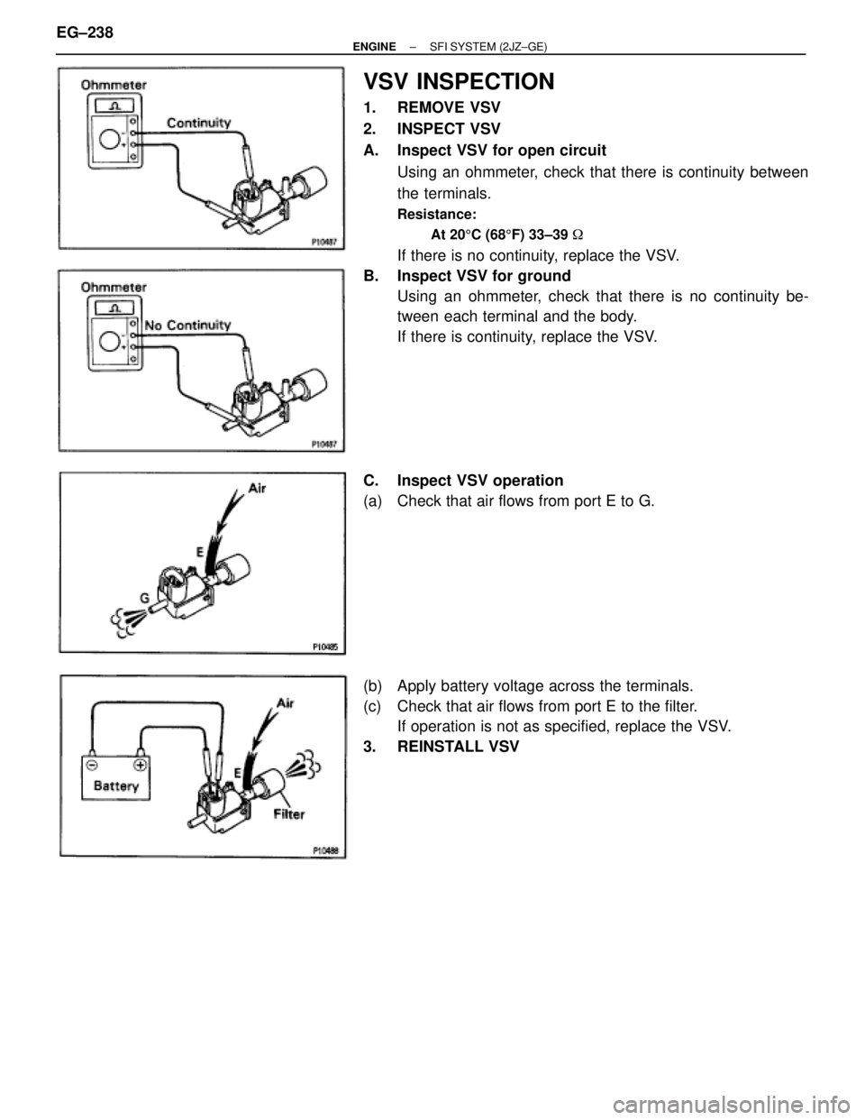
VSV INSPECTION
1. REMOVE VSV
2. INSPECT VSV
A. Inspect VSV for open circuit
Using an ohmmeter, check that there is continuity between
the terminals.
Resistance:
At 205C (685F) 33±39 �
If there is no continuity, replace the VSV.
B. Inspect VSV for ground
Using an ohmmeter, check that there is no continuity be-
tween each terminal and the body.
If there is continuity, replace the VSV.
C. Inspect VSV operation
(a) Check that air flows from port E to G.
(b) Apply battery voltage across the terminals.
(c) Check that air flows from port E to the filter.
If operation is not as specified, replace the VSV.
3. REINSTALL VSV EG±238
± ENGINESFI SYSTEM (2JZ±GE)
Page 391 of 878
 Check (main heated) oxygen sensors operation.
(See oxygen sensor(s) inspection")
Troubleshooting
If the CO/HC concentration does not comply with regulations,
troubleshoot in the order given below.
(a) Check (main heated) oxygen sensors operation.
(See oxygen sensor(s) inspection in SFI System)
(b) See the table below for possible causes, and then inspect
and correct the applicable causes if necessary.
���� ����CO����� �����HC������������ ������������Phenomenon������������������ ������������������Causes
���� �
��� �
��� �
��� �
��� �
��� �
��� �
��� ����
Normal����� �
���� �
���� �
���� �
���� �
���� �
���� �
���� �����
High������������ �
����������� �
����������� �
����������� �
����������� �
����������� �
����������� �
����������� ������������
Rough idle������������������ �
����������������� �
����������������� �
����������������� �
����������������� �
����������������� �
����������������� �
����������������� ������������������
1. Faulty ignitions:
�Incorrect timing
�Fouled, shorted or improperly gapped plugs
�Open or crossed high±tension cords (2JZ±GE)
�Cracked distributor cap (2JZ±GE)
2. Incorrect valve clearance
3. Leaky EGR valve
4. Leaky intake and exhaust valves
5. Leaky cylinder
���� �
��� �
��� �
��� �
��� �
��� �
��� �
��� ����
Low����� �
���� �
���� �
���� �
���� �
���� �
���� �
���� �����
High������������ �
����������� �
����������� �
����������� �
����������� �
����������� �
����������� �
����������� ������������
Rough idle
(Fluctuating HC reading)������������������ �
����������������� �
����������������� �
����������������� �
����������������� �
����������������� �
����������������� �
����������������� ������������������
1. Vacuum leaks:
�PCV hose
�EGR valve
�Intake manifold
�Air intake chamber
�Throttle body
�IAC valve
�Brake booster line
2. Lean mixture causing misfire
���� �
��� �
��� �
��� �
��� �
��� �
��� �
��� �
��� �
��� ����
High����� �
���� �
���� �
���� �
���� �
���� �
���� �
���� �
���� �
���� �����
High������������ �
����������� �
����������� �
����������� �
����������� �
����������� �
����������� �
����������� �
����������� �
����������� ������������
Rough idle
(Black smoke from exhaust)������������������ �
����������������� �
����������������� �
����������������� �
����������������� �
����������������� �
����������������� �
����������������� �
����������������� �
����������������� ������������������
1. Restricted air filter
2. Faulty SFI systems:
�Faulty fuel pressure regulator
�Clogged fuel return line
�Defective ECT switch
�Defective turbo pressure sensor (2JZ±GTE)
�Faulty ECM
�Faulty injector
�Faulty throttle position sensor
�Faulty VAF meter (2JZ±GE)
�Faulty MAF meter (2JZ±GTE)
EG±8± ENGINEENGINE MECHANICAL
Page 461 of 878

1. REMOVE HOOD
2. REMOVE RADIATOR ASSEMBLY
(See radiator removal in Cooling System)
3. DRAIN ENGINE OIL
4. DRAIN FUEL FROM FUEL TANK
5. DISCONNECT CONTROL CABLES FROM THROT")
ENGINE REMOVAL (2JZ±GE)
1. REMOVE HOOD
2. REMOVE RADIATOR ASSEMBLY
(See radiator removal in Cooling System)
3. DRAIN ENGINE OIL
4. DRAIN FUEL FROM FUEL TANK
5. DISCONNECT CONTROL CABLES FROM THROTTLE
BODY
Disconnect these cables:
wAccelerator cable
wCruise control actuator cable
6. REMOVE AIR CLEANER, VAF METER AND INTAKE AIR
CONNECTOR PIPE ASSEMBLY
(a) Disconnect the high±tension cord from the ignition coil.
(b) Disconnect the high±tension cord from the clamp on the air
cleaner.
(c) Disconnect the VAF meter connector.
(d) Disconnect the engine wire from the VAF meter.
(e) Disconnect these hoses:
(1) PS air hose from No.4 timing belt cover
(2) PCV hose from No.2 cylinder head cover
(f) Loosen the hose clamp bolt holding the intake air connector
pipe to the throttle body.
(g) Remove the 3 bolts, air cleaner, VAF meter and intake air
connector pipe assembly.
7. REMOVE DRIVE BELT, FAN, FLUID COUPLING
ASSEMBLY AND WATER PUMP PULLEY
(See step 6 in water pump removal in Cooling System)
8. REMOVE CHARCOAL CANISTER
9. DISCONNECT HEATER WATER HOSES
10. DISCONNECT BRAKE BOOSTER VACUUM HOSE
11. DISCONNECT EVAP HOSE
12. DISCONNECT WIRES AND CONNECTORS
(a) Disconnect the noise filter connector.
(b) Disconnect the ignition coil connector.
(c) Disconnect the engine wire from the wire clamp. EG±78
± ENGINEENGINE MECHANICAL
Page 550 of 878
EVAPORATIVE EMISSION (EVAP)
CONTROL SYSTEM
FUEL VAPOR LINES, FUEL TANK AND
TANK CAP INSPECTION
1. VISUALLY INSPECT LINES AND CONNECTIONS
Look for loose connections, sharp bends or damage.
2. VISUALLY INSPECT FUEL TANK
Look for deformation, cracks or fuel leakage.
3. VISUALLY INSPECT FUEL TANK CAP
Check if the cap and/or gasket are deformed or damaged.
If necessary, repair or replace the cap.
CHARCOAL CANISTER INSPECTION
1. REMOVE CHARCOAL CANISTER
2. VISUALLY INSPECT CHARCOAL CANISTER
Look for cracks or damage.
3. CHECK FOR CLOGGED FILTER AND STUCK CHECK
VA LV E
(a) Using low pressure compressed air (4.71 kPa (0.048
kgf/cm
2, 0.68 psi)), blow into port C and check that air flows
without resistance from the other ports. EG±178
± ENGINEEMISSION CONTROL SYSTEMS (2JZ±GTE)
 38.5±44.5")
 Check that air flows from port E to the filter.
(b) Apply battery voltage across the terminals.
(c) Check that air flows from port E to F.
If operation is not as speci")

CONTROL SYSTEM
FUEL VAPOR LINES, FUEL TANK AND
TANK CAP INSPECTION
1. VISUALLY INSPECT LINES AND CONNECTIONS
Look for loose connections, sharp bends or damage.
2. VISUALL")