Page 11 of 878
TURBOCHARGER REMOVAL
Installation is in the reverse order of removal.
1. DRAIN ENGINE COOLANT
2. REMOVE ENGINE UNDER COVER
3. DISCONNECT CRUISE CONTROL ACTUATOR CABLE
FROM THROTTLE BODY
4. REMOVE NO.1 AIR HOSE
5. REMOVE AIR CLEANER DUCT
6. REMOVE AIR CLEANER AND MAF METER ASSEMBLY
(a) Remove the 3 bolts.
(b) Loosen the hose clamp, disconnect the air hose from the
intake air connector.
(c) Disconnect the MAF meter wire from the clamp on the air
cleaner case.
(d) Disconnect the MAF meter connector, and remove the air
cleaner and MAF meter assembly. EG±150
± ENGINETURBOCHARGER SYSTEM (2JZ±GTE)
Page 95 of 878
INSPECTION PROCEDURE
(See page EG±510)
(1) Shift the shift lever to N position.
(2) Jack up one of the rear wheels.
(3) Connect SST (check harness ªAº).
(See page
EG±510)
(4) Disconnect power steering ECU connector
and cruise control ECU connector.
(5) Turn ignition switch ON.
Measure voltage between terminal SP1 of engine
control module connector and body ground when
the wheel is turned slowly.
Voltage is generated intermittently.
Check voltage between terminal SP1 of engine control module connector
and body ground.
Check and replace engine control module.
Repair or replace harness or connector between
ECM and telltale light RH.
Repair or replace harness or connector between
telltale light RH and No.1 vehicle speed sensor.
Replace No.1 vehicle speed sensor.
Check operation of odometer and trip meter (telltale light RH
(See page Be±48)).
Check operation of No.1 vehicle speed sensor (See page BE±46).
EG±558± ENGINE2JZ±GTE ENGINE TROUBLESHOOTING
Page 203 of 878
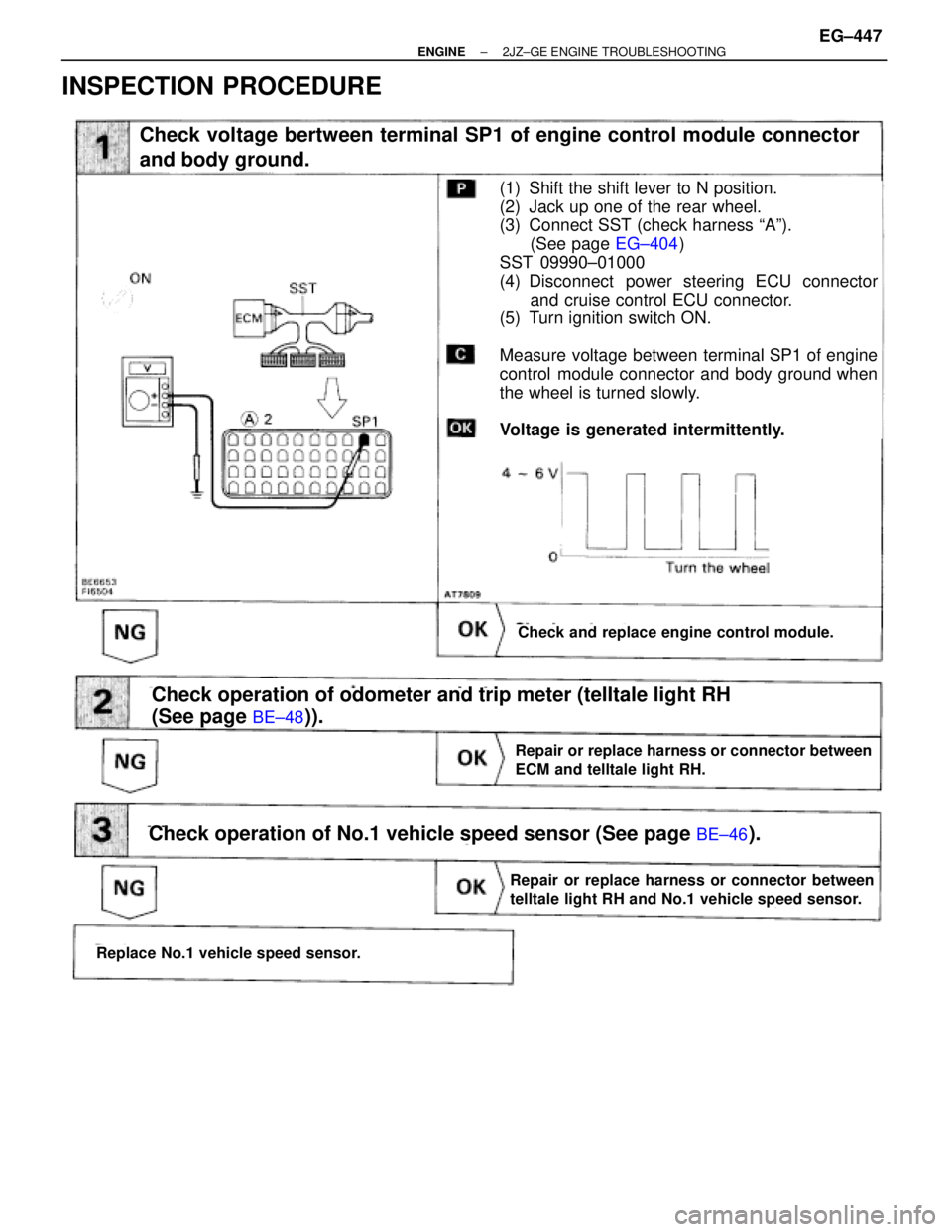
INSPECTION PROCEDURE
(See page
EG±404)
(See page BE±48)).
Check voltage bertween terminal SP1 of engine control module connector
and body ground.
Check and replace engine control module.
(1) Shift the shift lever to N position.
(2) Jack up one of the rear wheel.
(3) Connect SST (check harness ªAº).
(See page EG±404)
SST 09990±01000
(4) Disconnect power steering ECU connector
and cruise control ECU connector.
(5) Turn ignition switch ON.
Measure voltage between terminal SP1 of engine
control module connector and body ground when
the wheel is turned slowly.
Voltage is generated intermittently.
Repair or replace harness or connector between
ECM and telltale light RH.
Check operation of odometer and trip meter (telltale light RH
(See page
BE±48)).
Check operation of No.1 vehicle speed sensor (See page BE±46).
Replace No.1 vehicle speed sensor.
Repair or replace harness or connector between
telltale light RH and No.1 vehicle speed sensor.
± ENGINE2JZ±GE ENGINE TROUBLESHOOTINGEG±447
Page 275 of 878
THROTTLE BODY REMOVAL
Installation is in the reverse order of removal.
1. DRAIN ENGINE COOLANT
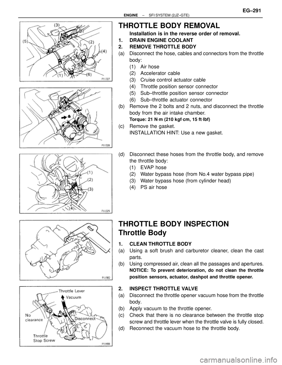
2. REMOVE THROTTLE BODY
(a) Disconnect the hose, cables and connectors from the throttle
body:
(1) Air hose
(2) Accelerator cable
(3) Cruise control actuator cable
(4) Throttle position sensor connector
(5) Sub±throttle position sensor connector
(6) Sub±throttle actuator connector
(b) Remove the 2 bolts and 2 nuts, and disconnect the throttle
body from the air intake chamber.
Torque: 21 NVm (210 kgfVcm, 15 ftVlbf)
(c) Remove the gasket.
INSTALLATION HINT: Use a new gasket.
(d) Disconnect these hoses from the throttle body, and remove
the throttle body:
(1) EVAP hose
(2) Water bypass hose (from No.4 water bypass pipe)
(3) Water bypass hose (from cylinder head)
(4) PS air hose
THROTTLE BODY INSPECTION
Throttle Body
1. CLEAN THROTTLE BODY
(a) Using a soft brush and carburetor cleaner, clean the cast
parts.
(b) Using compressed air, clean all the passages and apertures.
NOTICE: To prevent deterioration, do not clean the throttle
position sensors, actuator, dashpot and throttle opener.
2. INSPECT THROTTLE VALVE
(a) Disconnect the throttle opener vacuum hose from the throttle
body.
(b) Apply vacuum to the throttle opener.
(c) Check that there is no clearance between the throttle stop
screw and throttle lever when the throttle valve is fully closed.
(d) Reconnect the vacuum hose to the throttle body.
± ENGINESFI SYSTEM (2JZ±GTE)EG±291
Page 400 of 878
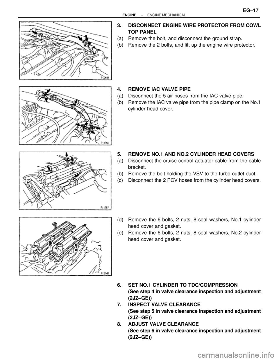
3. DISCONNECT ENGINE WIRE PROTECTOR FROM COWL
TOP PANEL
(a) Remove the bolt, and disconnect the ground strap.
(b) Remove the 2 bolts, and lift up the engine wire protector.
4. REMOVE IAC VALVE PIPE
(a) Disconnect the 5 air hoses from the IAC valve pipe.
(b) Remove the IAC valve pipe from the pipe clamp on the No.1
cylinder head cover.
5. REMOVE NO.1 AND NO.2 CYLINDER HEAD COVERS
(a) Disconnect the cruise control actuator cable from the cable
bracket.
(b) Remove the bolt holding the VSV to the turbo outlet duct.
(c) Disconnect the 2 PCV hoses from the cylinder head covers.
(d) Remove the 6 bolts, 2 nuts, 8 seal washers, No.1 cylinder
head cover and gasket.
(e) Remove the 6 bolts, 2 nuts, 8 seal washers, No.2 cylinder
head cover and gasket.
6. SET NO.1 CYLINDER TO TDC/COMPRESSION
(See step 4 in valve clearance inspection and adjustment
(2JZ±GE))
7. INSPECT VALVE CLEARANCE
(See step 5 in valve clearance inspection and adjustment
(2JZ±GE))
8. ADJUST VALVE CLEARANCE
(See step 6 in valve clearance inspection and adjustment
(2JZ±GE))
± ENGINEENGINE MECHANICALEG±17
Page 401 of 878
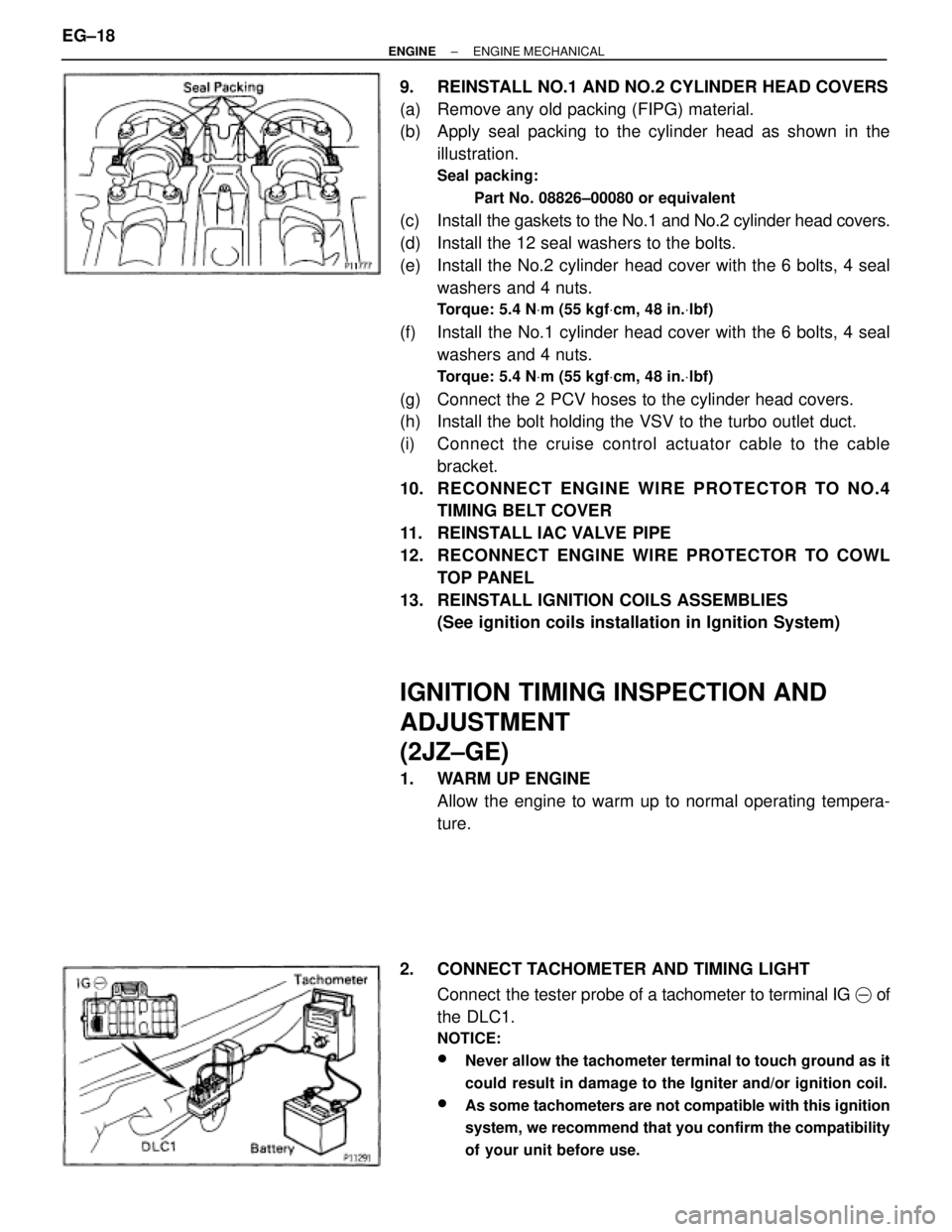
9. REINSTALL NO.1 AND NO.2 CYLINDER HEAD COVERS
(a) Remove any old packing (FIPG) material.
(b) Apply seal packing to the cylinder head as shown in the
illustration.
Seal packing:
Part No. 08826±00080 or equivalent
(c) Install the gaskets to the No.1 and No.2 cylinder head covers.
(d) Install the 12 seal washers to the bolts.
(e) Install the No.2 cylinder head cover with the 6 bolts, 4 seal
washers and 4 nuts.
Torque: 5.4 NVm (55 kgfVcm, 48 in.Vlbf)
(f) Install the No.1 cylinder head cover with the 6 bolts, 4 seal
washers and 4 nuts.
Torque: 5.4 NVm (55 kgfVcm, 48 in.Vlbf)
(g) Connect the 2 PCV hoses to the cylinder head covers.
(h) Install the bolt holding the VSV to the turbo outlet duct.
(i) Connect the cruise control actuator cable to the cable
bracket.
10. RECONNECT ENGINE WIRE PROTECTOR TO NO.4
TIMING BELT COVER
11. REINSTALL IAC VALVE PIPE
12. RECONNECT ENGINE WIRE PROTECTOR TO COWL
TOP PANEL
13. REINSTALL IGNITION COILS ASSEMBLIES
(See ignition coils installation in Ignition System)
IGNITION TIMING INSPECTION AND
ADJUSTMENT
(2JZ±GE)
1. WARM UP ENGINE
Allow the engine to warm up to normal operating tempera-
ture.
2. CONNECT TACHOMETER AND TIMING LIGHT
Connect the tester probe of a tachometer to terminal IG � of
the DLC1.
NOTICE:
wNever allow the tachometer terminal to touch ground as it
could result in damage to the Igniter and/or ignition coil.
wAs some tachometers are not compatible with this ignition
system, we recommend that you confirm the compatibility
of your unit before use.
EG±18± ENGINEENGINE MECHANICAL
Page 432 of 878
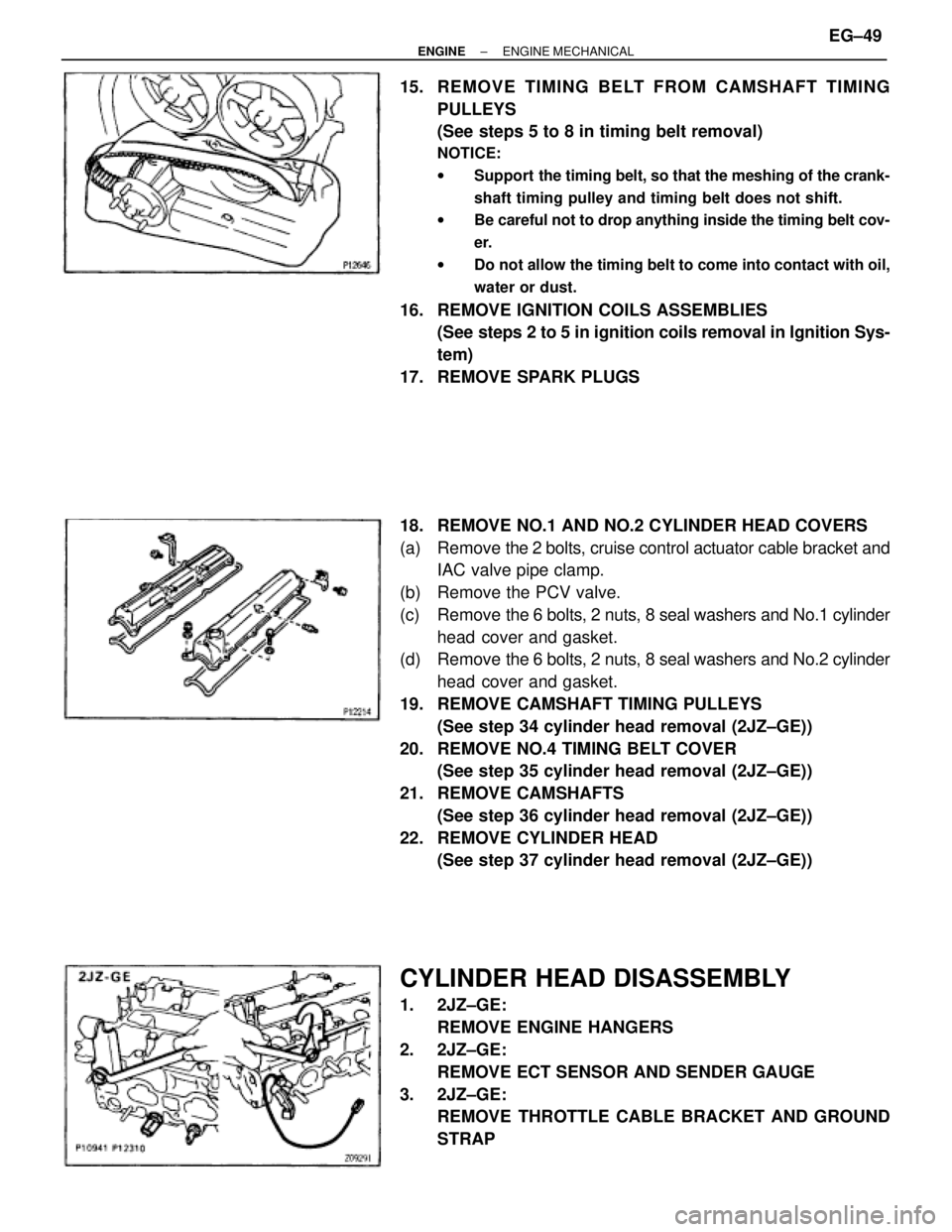
15. REMOVE TIMING BELT FROM CAMSHAFT TIMING
PULLEYS
(See steps 5 to 8 in timing belt removal)
NOTICE:
wSupport the timing belt, so that the meshing of the crank-
shaft timing pulley and timing belt does not shift.
wBe careful not to drop anything inside the timing belt cov-
er.
wDo not allow the timing belt to come into contact with oil,
water or dust.
16. REMOVE IGNITION COILS ASSEMBLIES
(See steps 2 to 5 in ignition coils removal in Ignition Sys-
tem)
17. REMOVE SPARK PLUGS
18. REMOVE NO.1 AND NO.2 CYLINDER HEAD COVERS
(a) Remove the 2 bolts, cruise control actuator cable bracket and
IAC valve pipe clamp.
(b) Remove the PCV valve.
(c) Remove the 6 bolts, 2 nuts, 8 seal washers and No.1 cylinder
head cover and gasket.
(d) Remove the 6 bolts, 2 nuts, 8 seal washers and No.2 cylinder
head cover and gasket.
19. REMOVE CAMSHAFT TIMING PULLEYS
(See step 34 cylinder head removal (2JZ±GE))
20. REMOVE NO.4 TIMING BELT COVER
(See step 35 cylinder head removal (2JZ±GE))
21. REMOVE CAMSHAFTS
(See step 36 cylinder head removal (2JZ±GE))
22. REMOVE CYLINDER HEAD
(See step 37 cylinder head removal (2JZ±GE))
CYLINDER HEAD DISASSEMBLY
1. 2JZ±GE:
REMOVE ENGINE HANGERS
2. 2JZ±GE:
REMOVE ECT SENSOR AND SENDER GAUGE
3. 2JZ±GE:
REMOVE THROTTLE CABLE BRACKET AND GROUND
STRAP
± ENGINEENGINE MECHANICALEG±49
Page 453 of 878
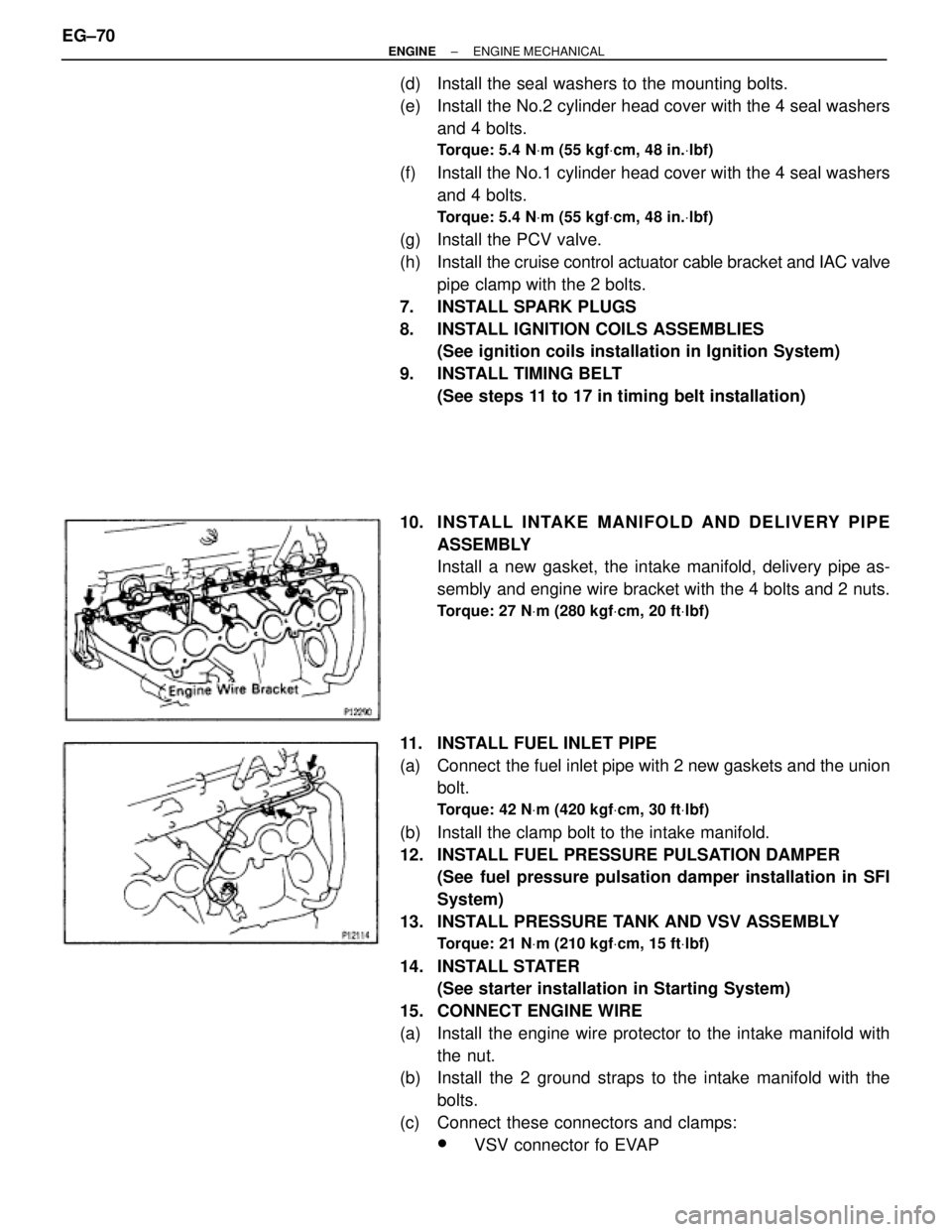
(d) Install the seal washers to the mounting bolts.
(e) Install the No.2 cylinder head cover with the 4 seal washers
and 4 bolts.
Torque: 5.4 NVm (55 kgfVcm, 48 in.Vlbf)
(f) Install the No.1 cylinder head cover with the 4 seal washers
and 4 bolts.
Torque: 5.4 NVm (55 kgfVcm, 48 in.Vlbf)
(g) Install the PCV valve.
(h) Install the cruise control actuator cable bracket and IAC valve
pipe clamp with the 2 bolts.
7. INSTALL SPARK PLUGS
8. INSTALL IGNITION COILS ASSEMBLIES
(See ignition coils installation in Ignition System)
9. INSTALL TIMING BELT
(See steps 11 to 17 in timing belt installation)
10. INS TALL INTAKE MANIFO LD AND DE LIV E RY PIP E
ASSEMBLY
Install a new gasket, the intake manifold, delivery pipe as-
sembly and engine wire bracket with the 4 bolts and 2 nuts.
Torque: 27 NVm (280 kgfVcm, 20 ftVlbf)
11. INSTALL FUEL INLET PIPE
(a) Connect the fuel inlet pipe with 2 new gaskets and the union
bolt.
Torque: 42 NVm (420 kgfVcm, 30 ftVlbf)
(b) Install the clamp bolt to the intake manifold.
12. INSTALL FUEL PRESSURE PULSATION DAMPER
(See fuel pressure pulsation damper installation in SFI
System)
13. INSTALL PRESSURE TANK AND VSV ASSEMBLY
Torque: 21 NVm (210 kgfVcm, 15 ftVlbf)
14. INSTALL STATER
(See starter installation in Starting System)
15. CONNECT ENGINE WIRE
(a) Install the engine wire protector to the intake manifold with
the nut.
(b) Install the 2 ground straps to the intake manifold with the
bolts.
(c) Connect these connectors and clamps:
wVSV connector fo EVAP EG±70
± ENGINEENGINE MECHANICAL