Page 57 of 878
 Remove ignition coil. (See page IG±26)
(2) Remove spark plug.
(3) Install the spark plug to the ignition coil, and connect
the ignition coil connector.
(4) Ground the spark plug.")
Check for spark.
(1) Remove ignition coil. (See page IG±26)
(2) Remove spark plug.
(3) Install the spark plug to the ignition coil, and connect
the ignition coil connector.
(4) Ground the spark plug.
Check if spark occurs while engine is being cranked.
To prevent excess fuel being injected from injectors dur-
ing this test, don't crank the engine for more than 1Ð2
seconds at a time.
Check for open and short in harness and connector in IGF signal circuit
between engine control module and igniter (See page IN±30).
Repair or replace harness or connector.
Replace igniter.
Check and replace engine control module.
Disconnect igniter connector and check voltage between terminal IGF of
engine control module connector and body ground.
(1) Disconnect igniter connector.
(2) Connect SST (check harness ªAº).
(See page EG±510)
SST 09990±01000
(3) Turn ignition switch ON.
Measure voltage between terminal IGF of engine con-
trol module connector and body ground.
Voltage: 4.5 Ð 5.5 V
INSPECTION PROCEDURE
EG±520± ENGINE2JZ±GTE ENGINE TROUBLESHOOTING
Page 58 of 878
(See page EG±510)
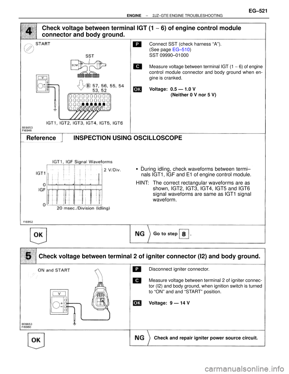
�During idling, check waveforms between termi±
nals IGT1, IGF and E1 of engine control module.
HINT: The correct rectangular waveforms are as
shown, IGT2, IGT3, IGT4, IGT5 and IGT6
signal waveforms are same as IGT1 signal
waveform.
Check voltage between terminal IGT (1 ~ 6) of engine control module
connector and body ground.
Connect SST (check harness ªAº).
(See page EG±510)
SST 09990±01000
Measure voltage between terminal IGT (1 ~ 6) of engine
control module connector and body ground when en-
gine is cranked.
Voltage: 0.5 Ð 1.0 V
(Neither 0 V nor 5 V)
Check voltage between terminal 2 of igniter connector (I2) and body ground.
Disconnect igniter connector.
Measure voltage between terminal 2 of igniter connec-
tor (I2) and body ground, when ignition switch is turned
to ªONº and and ªSTARTº position.
Voltage: 9 Ð 14 V
Check and repair igniter power source circuit.
ReferenceINSPECTION USING OSCILLOSCOPE
± ENGINE2JZ±GTE ENGINE TROUBLESHOOTINGEG±521
Page 59 of 878
Check for open and short in harness and connector between ignition
switch and ignition coil, ignition coil and igniter (See page IN±30).
Disconnect ignition coil connector.
(See page IG±23)
Measure resistance between terminals of ignition coil
connector.
Repair or replace harness or connector.
Check ignition coil.
ªColdº is from Ð 10°C (14°F) to 50°C (122°F) and ªHotº is
from 50°C (122°F) to 100°C (212°F).
Replace ignition coil.
Replace igniter.
EG±522± ENGINE2JZ±GTE ENGINE TROUBLESHOOTING
Page 60 of 878
Disconnect igniter connector and check voltage between terminal
IGT (1 ~ 6) of engine control module connector and body ground.
Disconnect igniter connector.
Measure voltage between terminal IGT (1 ~ 6) of engine
control module connector and body ground when engine
is cranked.
Voltage: 0.5 Ð 1.0 V
(Neither 0 V nor 5 V)
Replace igniter.
Check for open and short in harness and connector in IGT (1 ~ 6) signal
circuit between engine control module and igniter (See page IN±30).
�During idling, check waveforms between terminals
IGF1, IGF and E1 of engine control module.
HINT: The correct rectangular waveforms are as shown,
IGT2, IGT3, IGT4, IGT5 and IGT6 signal wave±
forms are same as IGT1 signal waveform.
Repair or replace harness or connector.
Check and replace engine control module.
ReferenceINSPECTION USING OSCILLOSCOPE
± ENGINE2JZ±GTE ENGINE TROUBLESHOOTINGEG±523
Page 63 of 878

DIAGNOSTIC TROUBLE CODE DETECTION DRIVING PATTERN
Purpose of the driving pattern.
(a) To simulate diagnostic trouble code detecting condition after diagnostic trouble co")
CIRCUIT DESCRIPTION (Cont'd)
DIAGNOSTIC TROUBLE CODE DETECTION DRIVING PATTERN
Purpose of the driving pattern.
(a) To simulate diagnostic trouble code detecting condition after diagnostic trouble code is recorded.
(b) To check that the malfunction is corrected when the repair is completed confirming that diagnostic trouble
code is no longer detected.
Malfunction: Main Heated Oxygen Sensor Deterioration
It is vital that this test routine is adhered to detect the malfunction:
(1) Disconnect the EFI No.1 fuse (30 A) for 10 sec. or more, with IG switch OFF. Initiate test
mode (Connect terminal TE2 and E1 of data link connector 2 with IG switch OFF).
(2) Start the engine and warm up with all ACC switch OFF.
(3) Idle the engine for 3 min.
(4) Accelerate gradually within the range 1,300 ~ 1,7700 rpm (centered around 1,500 rpm) with
the A/C switch ON and D position for A/T (5th for M/T).
HINT:�Ensure engine rpm does NOT fall below 1200 rpm.
�Gradually depress the accelerator pedal at a suitable rate to comply with the test re±
quirements on the above graph.
�Never allow engine rpm to drop at any time during the test.
(5) Maintain the vehicle speed at 64 Ð 80 km/h (40 Ð 50 mph).
(6) Keep the vehicle running for Ð 2 min. after starting acceleration.
HINT: If a malfunction exists, the Malfunction Indicator Lamp will light up after approx. 60 sec.
from the start of acceleration.
NOTICE: If the conditions in this test are not strictly followed, detection of the malfunc±
tion will not be possible. EG±526
± ENGINE2JZ±GTE ENGINE TROUBLESHOOTING
Page 64 of 878
Connect SST (check harness ªAº).
(See page EG±510)
SST 09990±01000
Measure voltage between terminals HT1 of engine
control module connector and body ground.
Voltage: 9 Ð 14 V
Check voltage between terminals HT1 of engine control module
connector and body ground.
INSPECTION PROCEDURE
± ENGINE2JZ±GTE ENGINE TROUBLESHOOTINGEG±527
Page 65 of 878

Check main heated oxygen")
Disconnect main heated oxygen sensor connector.
Measure resistance between terminals 1 and 2 of
main heated oxygen sensor connector.
Resistance: 11 Ð 16 � at 20°C (68°F)
Check main heated oxygen sensor heater.
Replace main heated oxygen sensor.
Check and repair harness or connector between
main relay and main heated oxygen sensor, main
heated oxygen sensor and engine control module.
Warm up engine to normal operating temperature.
Measure voltage between terminals HT1 of engine
control module connector and body ground, when
engine is idling and racing at 4,000 rpm.
Check voltage between terminals HT1 of engine control module connector
and body ground.
Replace main heated oxygen sensor.*
Check and replace engine control module.
In the 4,000 rpm racing check, continue engine
racing at 4,000 rpm for approx. 20 seconds or
more.
*: It is probable the oxygen sensor has deteri±
orated. Usually, this cannot be confirmed by
visual inspection. EG±528
± ENGINE2JZ±GTE ENGINE TROUBLESHOOTING
Page 68 of 878

(1) Connect SST (check harness ªAº).
(See page EG±510)
(2) Turn ignition switch ON
Measure voltage between terminals THW and
E2 of engine control module connector.
Check voltage")
(See page EG±510)
(1) Connect SST (check harness ªAº).
(See page EG±510)
(2) Turn ignition switch ON
Measure voltage between terminals THW and
E2 of engine control module connector.
Check voltage between terminals THW and E2 of engine control module
connector.
Check for intermittent problems.
(See page EG±505)
Disconnect the engine coolant temp. sensor con-
nector.
Measure resistance between terminals.
Resistance is within Acceptale Zone on chart.
Check engine coolant temp. sensor.
Replace engine coolant temp. sensor.
Repair or replace harness or connector.
Check and replace engine control module.
Check for open and short in harness and connector between engine control
module and engine coolant temp. sensor (See page IN±30).
INSPECTION PROCEDURE
HINT: If diagnostic trouble codes º22º (engine coolant temperature sensor circuit), º24º (intake air temperature
sensor circuit) and º41º (throttle position sensor circuit) are output simultaneously, E2 (sensor ground)
may be open.
± ENGINE2JZ±GTE ENGINE TROUBLESHOOTINGEG±531
.
Disconnect ignition coil connector.
(See page IG±23)
Measure")
 of engine control module connector and body ground.
Disconnect igniter connector.
Measure voltage between terminal IGT (1 ~")
.
(See page EG±510)
SST 09990±01000
Measure voltage between terminals HT1 of engine
control module connector and body ground.
Voltage: 9 Ð 14 V
Check voltage betwe")