Page 80 of 878
(See page EG±321)
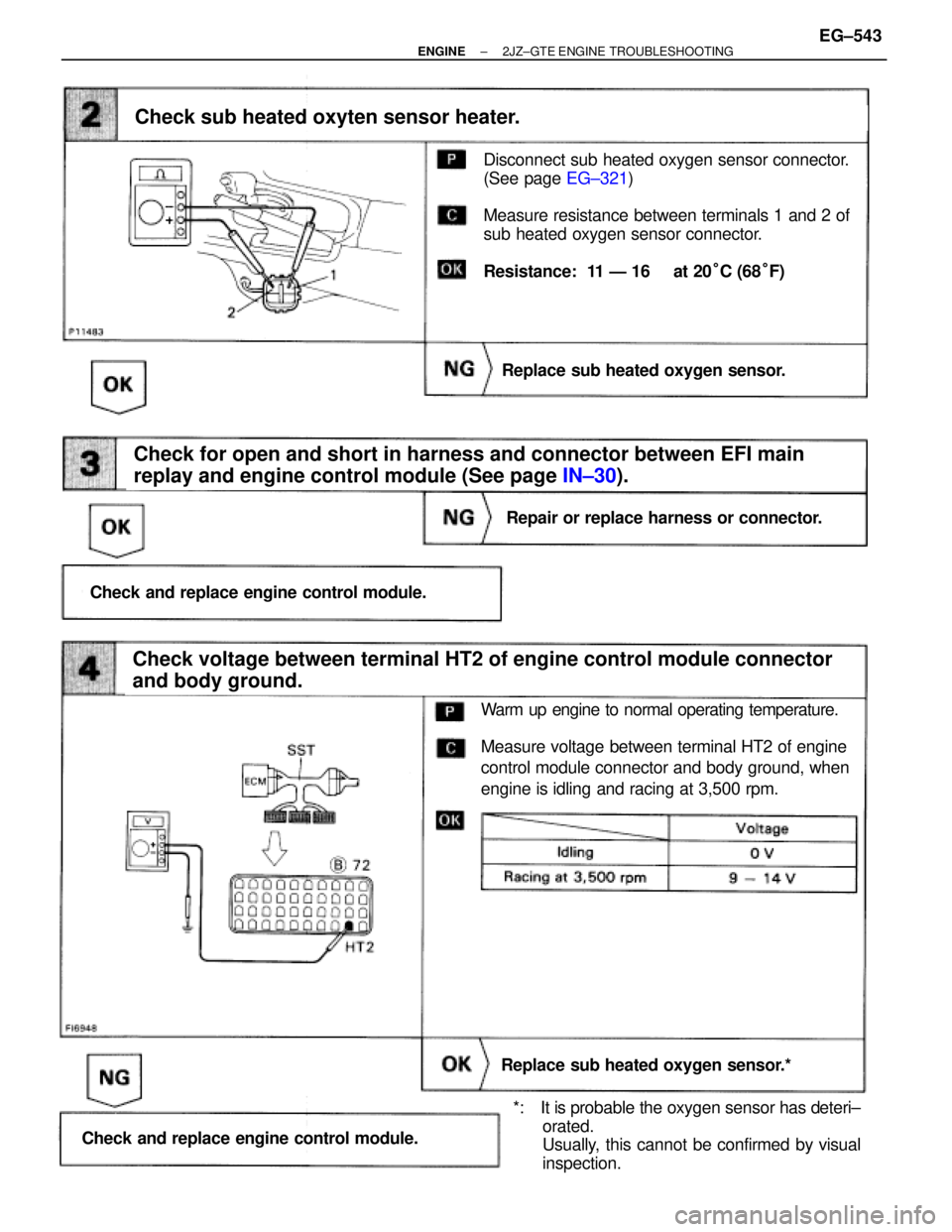
Disconnect sub heated oxygen sensor connector.
(See page EG±321)
Measure resistance between terminals 1 and 2 of
sub heated oxygen sensor connector.
Resistance: 11 Ð 16 � at 20°C (68°F)
Check for open and short in harness and connector between EFI main
replay and engine control module (See page IN±30).
Check sub heated oxyten sensor heater.
Replace sub heated oxygen sensor.
Repair or replace harness or connector.
Check and replace engine control module.
Check voltage between terminal HT2 of engine control module connector
and body ground.
Replace sub heated oxygen sensor.*
Check and replace engine control module.
Warm up engine to normal operating temperature.
Measure voltage between terminal HT2 of engine
control module connector and body ground, when
engine is idling and racing at 3,500 rpm.
*: It is probable the oxygen sensor has deteri±
orated.
Usually, this cannot be confirmed by visual
inspection.
± ENGINE2JZ±GTE ENGINE TROUBLESHOOTINGEG±543
Page 82 of 878
(See page IN±30).
(See page EG±510)(1) Connect SST (check harness ªAº).
(See page EG±510)
SST 09990±01000
(2) Start engine.
Measure voltage between terminals VG and E21 of
engine control module connector while engine rpm
at idling.
Voltage: 0.7 Ð 1.7 V
Check voltage between terminal 1 of mass air flow meter connector and
body ground.
Check voltage between terminals VG and E21 of engine control module
connector.
Check and replace engine control module
Check for open and short in harness and connector between engine
control module and mass air flow meter (See page IN±30).
Check and repair mass air flow meter power
source circuit.
Repair or replace harness or connector.
Replace mass air flow meter.
(1) Disconnect the mass air flow meter connector.
(2) Turn ignition switch ON.
Measure voltage between terminal 1 of mass air
flow meter connector and body ground.
Voltage: 9 Ð 14 V
INSPECTION PROCEDURE
± ENGINE2JZ±GTE ENGINE TROUBLESHOOTINGEG±545
Page 84 of 878
(1) Check actuator hose connection.
(2) Disconnect actuator hose.
(3) Using SST, apply pressure to the actuator.
SST 09992±00241
Waste gate valve operate smoothly.
Operation pressure:
119 kpa (1.2 kgf/cm
2, 17.3 psi) or less
Check operation of actuator.
Replace actuator.
INSPECTION PROCEDURE
± ENGINE2JZ±GTE ENGINE TROUBLESHOOTINGEG±547
Page 85 of 878
(See page EG±510)
(1) Remove VSV.
(2) Disconnect VSV connector.
Check operation of VSV for waste gate valve when
battery positive voltage is applied and released to
the VSV terminals.
Battery positivie voltage is applied:
Air from port E is flowing out through port F.
Battery positive voltage is applied:
Closed air passage from E to F.
Check voltage terminals PMC of engine control module connector and
body ground.
Check operation of VSV for waste gate valve.
Replace VSV for waste gate valve.
Check and repair harness and connector be-
tween VSV for waste gate valve and engine
control module.
(1) Connect SST (check harness ªAº).
(See page EG±510)
SST 09990±01000
(2) Turn ignition switch ON.
Measure voltage between terminals PMC of engine
control module and ground.
Voltage: 9 Ð 14 V
Check and replace enginie control module. EG±548
± ENGINE2JZ±GTE ENGINE TROUBLESHOOTING
Page 87 of 878
(See page EG±510)(1) Connect SST (check harness ªAº).
(See page EG±510)
SST 09990±01000
(2) Turn ignition switch ON.
Measure voltage between terminals VCC and E1
of engine control module.
Voltage: 4.5 Ð 5.5 V
Check voltage between terminals VCC and E1 of engine control module
connector.
Check and replace engine control module.
INSPECTION PROCEDURE
HINT: DTC 35 indicates trouble in the BARO sensor circuit or turbo pressure sensor circuit. Because all func±
tions of the BARO sensor circuit are built into the ECM, it is not possible to check this circuit.
However, if no problem is found in the turbo pressure sensor circuit, it can be concluded that the problem
is in the BARO sensor circuit. EG±550
± ENGINE2JZ±GTE ENGINE TROUBLESHOOTING
Page 88 of 878
(See page IN±30).
Turn ignition switch ON.
Measure voltage between terminals PM1 and E2
of engine control module.
Voltage: 2.3 Ð 3.0 V
Check voltage between terminals PM1 and E2 of engine control module.
Check for open and short in harness and connector between engine control
module and turbo pressure sensor (See page
IN±30).
Check and replace engine control module.
Repair or replace harness or connector.
Replace turbo pressure sensor.
± ENGINE2JZ±GTE ENGINE TROUBLESHOOTINGEG±551
Page 91 of 878

INSPECTION PROCEDURE
HINT:
wIf diagnostic trouble code 41 is displayed, check throttle position sensor circuit. If diagnostic trouble code
47 is displayed, check sub±throttle position sensor circuit.
wIf diagnostic trouble code º22º (engine coolant temperature sensor circuit), º24º (intake air temperature
sensor circuit) and º41º (throttle position sensor circuit) are output simultaneously. E2 (sensor ground) may
be open.
(See page EG±505)
(See page EG±510)
(See page EG±292)
Check voltage between terminals VTA1, 2, IDL1, 2 and E2 of engine control
module connector.
The voltage should increase steadily in proportion
to the throttle valve opening angle.
(1) Connect SST (check harness ªAº).
(See page EG±510)
SST 09990±01000
(2) Turn ignition switch ON.
(3) For throttle position sensor, disconnect the vacuum
hose from the throttle body, then apply vacuum to
the throttle opener.
(See page EG±292)
(4) For sub±throttle position sensor, remove intake air
duct and disconnect sub±throttle valve step motor
connector.
Measure voltage between terminals VTA1, 2, IDL1,
2 and E2 of engine control module connector when
the (sub±) throttle valve is opened gradually from
the closed condition.
Check for intermittent problems.
(See page
EG±505)
Throttle Valve
Terminal
Fully Closed
Fully Open
EG±554± ENGINE2JZ±GTE ENGINE TROUBLESHOOTING
Page 92 of 878
(1) Remove throttle body. (See page EG±291)
(2) For throttle position sensor, apply vacuum to
throttle opener. (See page
EG±292)
Measure resistance of each terminal as below table
when the throttle valve is opened gradually from the
closed condition.
Check throttle position sensor(s).
Check for open and short in harness and connector between engine control
module and throttle position sensors(s) (See page
IN±30).
Resistance between terminals 2,3 (VTA1,2) and 4,1
(E2) should increase gradually in accordance with
the throttle valve opening angle.
Adjust or replace throttle position sensor(s).
(See page EG±292)
Repair or replace harness or connector.
Check and replace engine control module.
For Throttle Position Sensor
For Sub±Throttle Position Sensor
Throttle Valve
Terminal
Throttle
Position
Sensor
Sub throttle
Position
Sensor
Fully
Closed Fully
Opened
± ENGINE2JZ±GTE ENGINE TROUBLESHOOTINGEG±555
.
(See page EG±510)(1) Connect SST (check harness ªAº).
(See page EG±510)
SST 09990±01000
(2) Start engine.
Measure voltage between terminals VG and E21 of
engine control module")
 Check actuator hose connection.
(2) Disconnect actuator hose.
(3) Using SST, apply pressure to the actuator.
SST 09992±00241
Waste gate valve operate smoothly.
Operation pressure:
119 kpa (1.2 kg")

(1) Remove VSV.
(2) Disconnect VSV connector.
Check operation of VSV for waste gate valve when
battery positive voltage is applied and released to
the VSV terminals.
Battery positiv")
(1) Connect SST (check harness ªAº).
(See page EG±510)
SST 09990±01000
(2) Turn ignition switch ON.
Measure voltage between terminals VCC and E1
of engine control module.
Voltage")
.
Turn ignition switch ON.
Measure voltage between terminals PM1 and E2
of engine control module.
Voltage: 2.3 Ð 3.0 V
Check voltage between terminals PM1 and E2 of engine control m")
 Remove throttle body. (See page EG±291)
(2) For throttle position sensor, apply vacuum to
throttle opener. (See page
EG±292)
Measure resistance of each terminal as below table
when the throttle")