Page 117 of 878
(See page IN±30).
Remove EFI main relay from R/B No.2.
Check continuity between terminals of EFI main
relay shown below.
Check EFI main relay.
(1) Apply battery positive voltage between termi±
nals 1 and 2.
(2) Check continuity between terminals 3 and 5.
Replace EFI main relay.
Repair or replace harness or connector.
Check for open and short in harness and connector between terminals
M±REL of engine control module and body ground (See page IN±30).
Check and repair harness or connector between EFI
No.1 fuse and battery.
Continuity
Continuity
Terminals 3 and 6
Terminals 3 and 5
Terminals 1 and 2 (Reference value 72 �)
Open
EG±580± ENGINE2JZ±GTE ENGINE TROUBLESHOOTING
Page 119 of 878
INSPECTION PROCEDURE
(See page EG±510)
Check and repair harness or connector between
engine control module and EFI No.1 fuse, EFI No.1
fuse and battery.
Remove EFI No.1 fuse from R/B No.2.
Check continuity of EFI No.1 fuse.
Continuity
Check EFI No.1 Fuse.
Check voltage between terminal BATT of engine control module connector
and body ground.
Connect SST (check harness ªAº).
See page EG±510)
SST 09990±01000
Measure voltage between terminal BATT of en-
gine control module connector and body ground.
Voltage: 9 Ð 14 V
Check for short in the harness and all the compo-
nents connected to EFI No.1 fuse (See attached
wiring diagram).
Are the diagnostic trouble codes still in the memory when the ignition switch
is turned OFF?
Check and replace engine control module.
Proceed to next circuit inspection shown on matrix
chart (See page EG±514).
EG±582± ENGINE2JZ±GTE ENGINE TROUBLESHOOTING
Page 121 of 878
INSPECTION PROCEDURE
Remove AM2 fuse from R/B No.2.
Check continuity of AM2 fuse.
Continuity
Check voltage between terminals # 10 ~ 60 of engine control module and
body ground.
Check AM2 fuse.
(1) Connect SST (check harness ªAº).
See page EG±510)
SST 09990±01000
(2) Turn ignition switch ON.
Measure voltage between terminals # 10 ~ 60 of en-
gine control module and body ground.
Voltage: 9 Ð 14 V
Check for short in the harness and all the components
connected to AM2 fuse.
EG±584± ENGINE2JZ±GTE ENGINE TROUBLESHOOTING
Page 122 of 878
.
Disconnect solenoid resistor connector.
Measure resistance between terminals 1 and 2
~
4, 6 ~ 8 of solenoid resistor connector.
Resistance: Approx. 6 � at 20°C (68°F)
Check res")
(See page IN±30).
Disconnect solenoid resistor connector.
Measure resistance between terminals 1 and 2
~
4, 6 ~ 8 of solenoid resistor connector.
Resistance: Approx. 6 � at 20°C (68°F)
Check resistance between terminals 1 and 2 ~ 4, 6 ~ 8 of solenoid resistor
connector.
Check for open in harness and connector between terminal E01, E02 of ECM
connector and body ground (See page IN±30).
Disconnect injector connector.
See page EG±273)
Measure resistance of injector.
Resistance: Approx. 1.95 � at 20°C (68°F)
Check injection volume of injector.
(See page EG±279)
�Injection volume
124
~ cm3/15 sec.
(7.6 Ð 8.8 cu in./15 sec.)
Difference between each injector:
Less than 10 cm
3 (0.6 cu in.)
�Leakage
Fuel drop: One drop or less per minute
Replace solenoid resistor.
Check and repair harness and connector
between engine control module and battery.
Repair or replace harness or connector.
Replace injector.
Check and replace engine control module.
Check injectors.
Check and replace engine control module.
± ENGINE2JZ±GTE ENGINE TROUBLESHOOTINGEG±585
Page 125 of 878
INSPECTION PROCEDURE
(See page IN±30).
(See page EG±514).
Disconnect IAC valve connector.
Measure resistance between terminals shown be-
low.
Check IAC valve.
Check for open and short in harness and connector between EFI main relay
and IAC valve, IAC valve and engine control module (See page IN±30).
Repair or replace harness or connector.
Remove IAC Valve.
(1) Connect the battery positive lead to terminals
5 (B1) and 2 (B2), and the negative lead to ter±
minals 4(S1)Ð1(S2)Ð6(S3)Ð3(S4) in that or
der.
(2) Connect the battery positive lead to terminals
5 (B1) and 2 (B2) and the negative lead to ter±
minals 3(S4)Ð6(S3)Ð1(S2)Ð4(S1) in that or
der.
(1) The valve moves in the closing direction
(2) The valve moves in the opening direction.
Replace IAC valve.
Proceed to next circuit inspection shown on ma-
trix chart (See page EG±514).
TerminalResistance
EG±588± ENGINE2JZ±GTE ENGINE TROUBLESHOOTING
Page 128 of 878
INSPECTION PROCEDURE
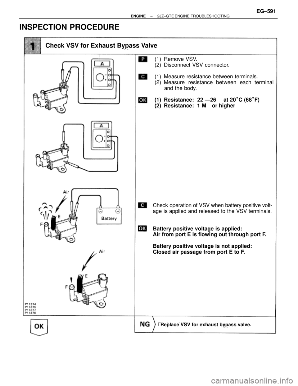
(1) Remove VSV.
(2) Disconnect VSV connector.
(1) Measure resistance between terminals.
(2) Measure resistance between each terminal
and the body.
(1) Resistance: 22 Ð26 � at 20°C (68°F)
(2) Resistance: 1 M� or higher
Check operation of VSV when battery positive volt-
age is applied and released to the VSV terminals.
Battery positive voltage is applied:
Air from port E is flowing out through port F.
Battery positive voltage is not applied:
Closed air passage from port E to F.
Check VSV for Exhaust Bypass Valve
Replace VSV for exhaust bypass valve.
± ENGINE2JZ±GTE ENGINE TROUBLESHOOTINGEG±591
Page 129 of 878
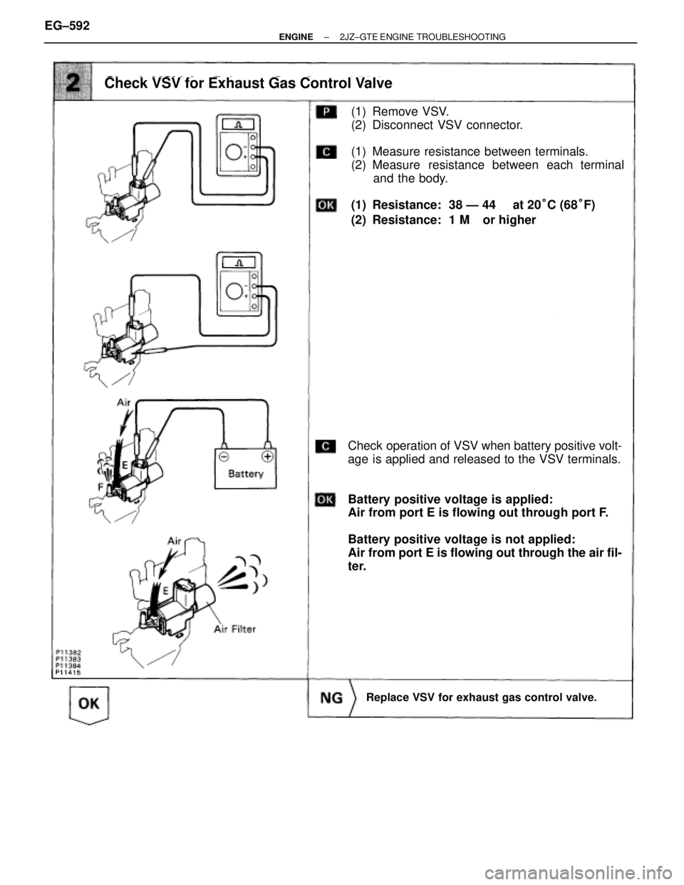
(1) Remove VSV.
(2) Disconnect VSV connector.
(1) Measure resistance between terminals.
(2) Measure resistance between each terminal
and the body.
(1) Resistance: 38 Ð 44 � at 20°C (68°F)
(2) Resistance: 1 M� or higher
Check operation of VSV when battery positive volt-
age is applied and released to the VSV terminals.
Battery positive voltage is applied:
Air from port E is flowing out through port F.
Battery positive voltage is not applied:
Air from port E is flowing out through the air fil-
ter.
Check VSV for Exhaust Gas Control Valve
Replace VSV for exhaust gas control valve.
EG±592± ENGINE2JZ±GTE ENGINE TROUBLESHOOTING
Page 130 of 878
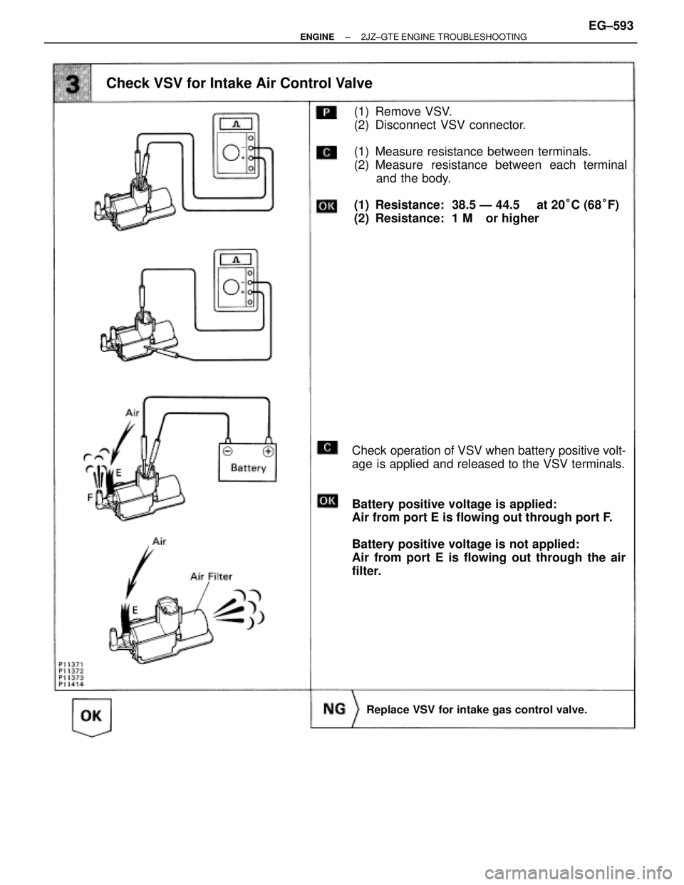
(1) Remove VSV.
(2) Disconnect VSV connector.
(1) Measure resistance between terminals.
(2) Measure resistance between each terminal
and the body.
(1) Resistance: 38.5 Ð 44.5 � at 20°C (68°F)
(2) Resistance: 1 M� or higher
Check operation of VSV when battery positive volt-
age is applied and released to the VSV terminals.
Battery positive voltage is applied:
Air from port E is flowing out through port F.
Battery positive voltage is not applied:
Air from port E is flowing out through the air
filter.
Check VSV for Intake Air Control Valve
Replace VSV for intake gas control valve.
± ENGINE2JZ±GTE ENGINE TROUBLESHOOTINGEG±593
.
Remove EFI main relay from R/B No.2.
Check continuity between terminals of EFI main
relay shown below.
Check EFI main relay.
(1) Apply battery positive voltage between termi±
nals")

Check and repair harness or connector between
engine control module and EFI No.1 fuse, EFI No.1
fuse and battery.
Remove EFI No.1 fuse from R/B No.2.
Check cont")
 Con")
.
(See page EG±514).
Disconnect IAC valve connector.
Measure resistance between terminals shown be-
low.
Check IAC valve.
Check for open and short in harness and")