Page 485 of 878
Bearing center wall thickness:
Mark º1º
1.492±1.495 mm (0.0587±0.0589 in.)
Mark º2º
1.495±1.498 mm (0.0589±0.0590 in.)
Mark º3º
1.498±1.501 mm (0.0590±0.0591 in.)
Mark º4º
1.501±1.504 mm (0.0591±0.0592 in.)
Mark º5º
1.504±1.507 mm (0.0592±0.0593 in.)
(j) Completely remove the Plastigage.
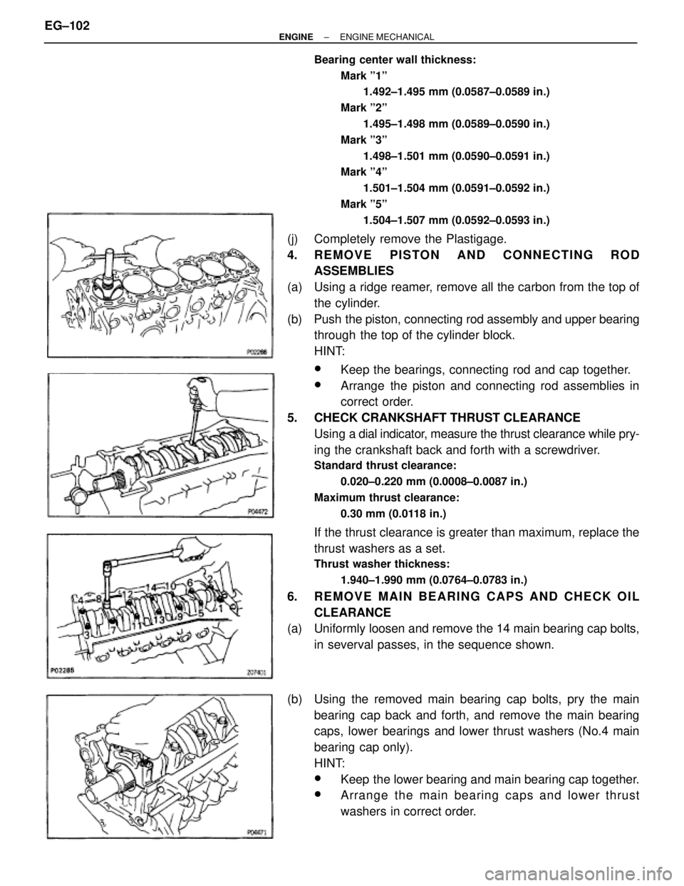
4. REMOVE PISTON AND CONNECTING ROD
ASSEMBLIES
(a) Using a ridge reamer, remove all the carbon from the top of
the cylinder.
(b) Push the piston, connecting rod assembly and upper bearing
through the top of the cylinder block.
HINT:
wKeep the bearings, connecting rod and cap together.
wArrange the piston and connecting rod assemblies in
correct order.
5. CHECK CRANKSHAFT THRUST CLEARANCE
Using a dial indicator, measure the thrust clearance while pry-
ing the crankshaft back and forth with a screwdriver.
Standard thrust clearance:
0.020±0.220 mm (0.0008±0.0087 in.)
Maximum thrust clearance:
0.30 mm (0.0118 in.)
If the thrust clearance is greater than maximum, replace the
thrust washers as a set.
Thrust washer thickness:
1.940±1.990 mm (0.0764±0.0783 in.)
6. REMOVE MAIN BEARING CAPS AND CHECK OIL
CLEARANCE
(a) Uniformly loosen and remove the 14 main bearing cap bolts,
in severval passes, in the sequence shown.
(b) Using the removed main bearing cap bolts, pry the main
bearing cap back and forth, and remove the main bearing
caps, lower bearings and lower thrust washers (No.4 main
bearing cap only).
HINT:
wKeep the lower bearing and main bearing cap together.
wArrange the main bearing caps and lower thrust
washers in correct order. EG±102
± ENGINEENGINE MECHANICAL
Page 489 of 878
CYLINDER BLOCK INSPECTION
1. CLEAN CYLINDER BLOCK
A. Remove gasket material
Using a gasket scraper, remove all the gasket material from
the cylinder block surface.
B. Clean cylinder block
Using a soft brush and solvent, thoroughly clean the cylinder
block.
2. INSPECT CYLINDER BLOCK SURFACE FOR FLATNESS
Using precision straight edge and feeler gauge, measure the
surfaces of the cylinder block for warpage.
Maximum warpage:
0.07 mm (0.0028 in.)
If warpage is greater than maximum, replace the cylinder
block.
3. INSPECT CYLINDER FOR VERTICAL SCRATCHES
Visually check the cylinder for vertical scratches.
If deep scratches are present, replace the cylinder block.
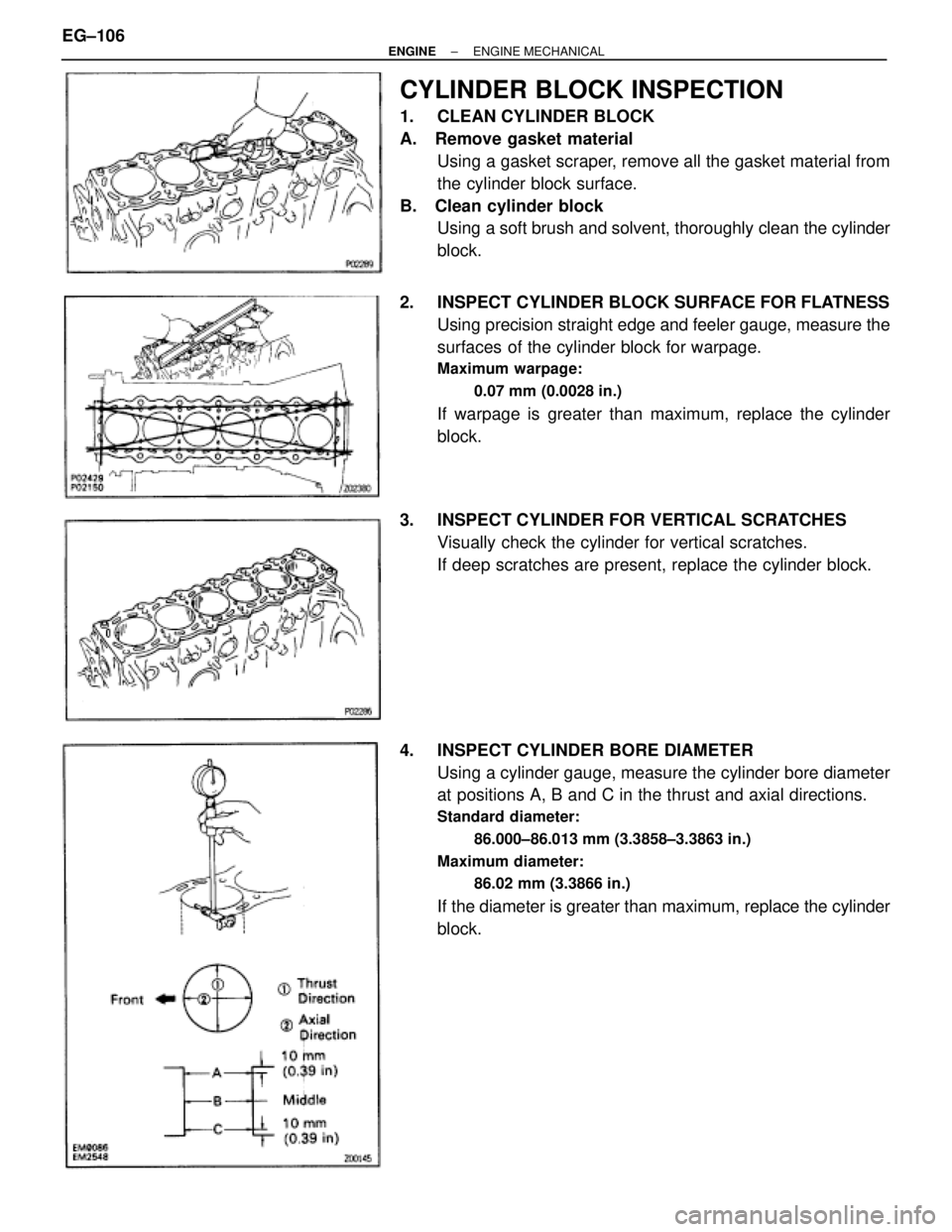
4. INSPECT CYLINDER BORE DIAMETER
Using a cylinder gauge, measure the cylinder bore diameter
at positions A, B and C in the thrust and axial directions.
Standard diameter:
86.000±86.013 mm (3.3858±3.3863 in.)
Maximum diameter:
86.02 mm (3.3866 in.)
If the diameter is greater than maximum, replace the cylinder
block. EG±106
± ENGINEENGINE MECHANICAL
Page 490 of 878
5. REMOVE CYLINDER RIDGE
If the wear is less than 0.2 mm (0.008 in.), using a ridge ream-
er, grind the top of the cylinder.
6. INSPECT MAIN BEARING CAP BOLTS
Using vernier calipers, measure the minimum diameter of the
compressed thread at the measuring point.
Standard diameter:
9.96±9.97 mm (0.3921±0.3925 in.)
Minimum diameter:
9.7 mm (0.382 in.)
If the diameter is less than minimum, replace the bolt.
PISTON AND CONNECTING ROD
DISASSEMBLY
1. CHECK FIT BETWEEN PISTON AND PISTON PIN
Try to move the piston back and forth on the piston pin.
If any movement is felt, replace the piston and pin as a set.
2. REMOVE PISTON RINGS
(a) Using a piston ring expander, remove the 2 compression
rings.
(b) Remove the 2 side rails and oil ring expander by hand.
HINT: Arrange the piston rings in correct order only.
3. DISCONNECT CONNECTING ROD FROM PISTON
(a) Using a small screwdriver, remove the 2 snap rings.
± ENGINEENGINE MECHANICALEG±107
Page 494 of 878
1041 W. 18th Street, Suite A210
Costa Mesa, California 92627
3. INSPECT CONNECTING ROD
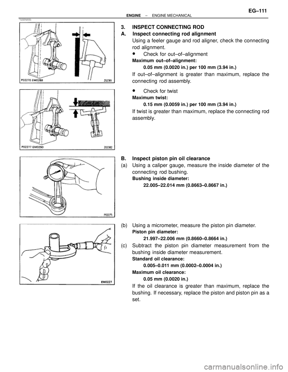
A. Inspect connecting rod alignment
Using a feeler gauge and rod aligner, check the connecting
rod alignment.
wCheck for out±of±alignment
Maximum out±of±alignment:
0.05 mm (0.0020 in.) per 100 mm (3.94 in.)
If out±of±alignment is greater than maximum, replace the
connecting rod assembly.
wCheck for twist
Maximum twist:
0.15 mm (0.0059 in.) per 100 mm (3.94 in.)
If twist is greater than maximum, replace the connecting rod
assembly.
B. Inspect piston pin oil clearance
(a) Using a caliper gauge, measure the inside diameter of the
connecting rod bushing.
Bushing inside diameter:
22.005±22.014 mm (0.8663±0.8667 in.)
(b) Using a micrometer, measure the piston pin diameter.
Piston pin diameter:
21.997±22.006 mm (0.8660±0.8664 in.)
(c) Subtract the piston pin diameter measurement from the
bushing inside diameter measurement.
Standard oil clearance:
0.005±0.011 mm (0.0002±0.0004 in.)
Maximum oil clearance:
0.05 mm (0.0020 in.)
If the oil clearance is greater than maximum, replace the
bushing. If necessary, replace the piston and piston pin as a
set.
± ENGINEENGINE MECHANICALEG±111
Page 495 of 878
C. If necessary, replace connecting rod bushing
(a) Using SST and a press, press out the bushing.
SST 09222±30010
(b) Align the oil holes of a new bushing and the connecting rod.
(c) Using SST and a press, press in the bushing.
SST 09222±30010
(d) Using a pin hole grinder, bore the bushing to obtain the
standard specified clearance (see step B) between the
bushing and piston pin.
(e) Check the piston pin fit at room temperature.
Coat the piston pin with engine oil and push it into the con-
necting rod with your thumb.
D. Inspect connecting rod bolts
Using vernier calipers, measure the minimum diameter of the
compressed bolt at the measuring point.
Standard diameter:
8.1±8.3 mm (0.319±0.327 in.)
Minimum diameter:
8.0 mm (0.315 in.)
If the diameter is less than minimum, replace the connecting
rod bolt. EG±112
± ENGINEENGINE MECHANICAL
Page 496 of 878
CRANKSHAFT INSPECTION
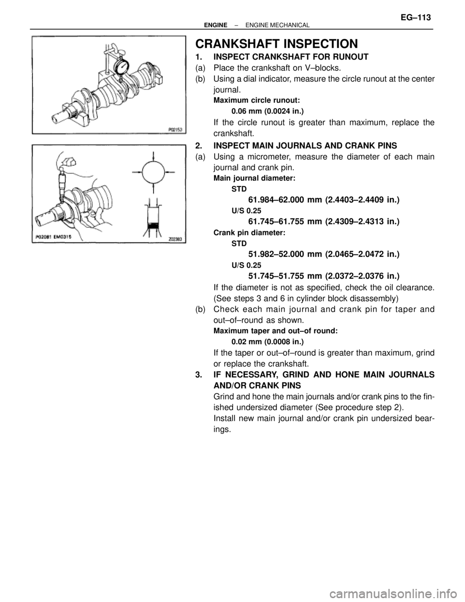
1. INSPECT CRANKSHAFT FOR RUNOUT
(a) Place the crankshaft on V±blocks.
(b) Using a dial indicator, measure the circle runout at the center
journal.
Maximum circle runout:
0.06 mm (0.0024 in.)
If the circle runout is greater than maximum, replace the
crankshaft.
2. INSPECT MAIN JOURNALS AND CRANK PINS
(a) Using a micrometer, measure the diameter of each main
journal and crank pin.
Main journal diameter:
STD
61.984±62.000 mm (2.4403±2.4409 in.)
U/S 0.25
61.745±61.755 mm (2.4309±2.4313 in.)
Crank pin diameter:
STD
51.982±52.000 mm (2.0465±2.0472 in.)
U/S 0.25
51.745±51.755 mm (2.0372±2.0376 in.)
If the diameter is not as specified, check the oil clearance.
(See steps 3 and 6 in cylinder block disassembly)
(b) Ch e ck ea ch ma in jo u rn a l an d cra n k pin fo r taper and
out±of±round as shown.
Maximum taper and out±of round:
0.02 mm (0.0008 in.)
If the taper or out±of±round is greater than maximum, grind
or replace the crankshaft.
3. IF NECESSARY, GRIND AND HONE MAIN JOURNALS
AND/OR CRANK PINS
Grind and hone the main journals and/or crank pins to the fin-
ished undersized diameter (See procedure step 2).
Install new main journal and/or crank pin undersized bear-
ings.
± ENGINEENGINE MECHANICALEG±113
Page 502 of 878
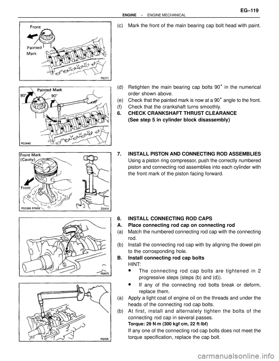
(c) Mark the front of the main bearing cap bolt head with paint.
(d) Retighten the main bearing cap bolts 90° in the numerical
order shown above.
(e) Check that the painted mark is now at a 90° angle to the front.
(f) Check that the crankshaft turns smoothly.
6. CHECK CRANKSHAFT THRUST CLEARANCE
(See step 5 in cylinder block disassembly)
7. INSTALL PISTON AND CONNECTING ROD ASSEMBLIES
Using a piston ring compressor, push the correctly numbered
piston and connecting rod assemblies into each cylinder with
the front mark of the piston facing forward.
8. INSTALL CONNECTING ROD CAPS
A. Place connecting rod cap on connecting rod
(a) Match the numbered connecting rod cap with the connecting
rod.
(b) Install the connecting rod cap with by aligning the dowel pin
to the corrosponding hole.
B. Install connecting rod cap bolts
HINT:
wThe connecting rod cap bolts are tightened in 2
progressive steps (steps (b) and (d)).
wIf any of the connecting rod bolts break or deform,
replace them.
(a) Apply a light coat of engine oil on the threads and under the
heads of the connecting rod cap bolts.
(b) A t first, in sta ll an d alte rn a te ly tig h te n th e bo lts of th e
connecting rod cap in several passes.
Torque: 29 NVm (300 kgfVcm, 22 ftVlbf)
If any one of the connecting rod cap bolts does not meet the
torque specification, replace the cap bolt.
± ENGINEENGINE MECHANICALEG±119
Page 503 of 878
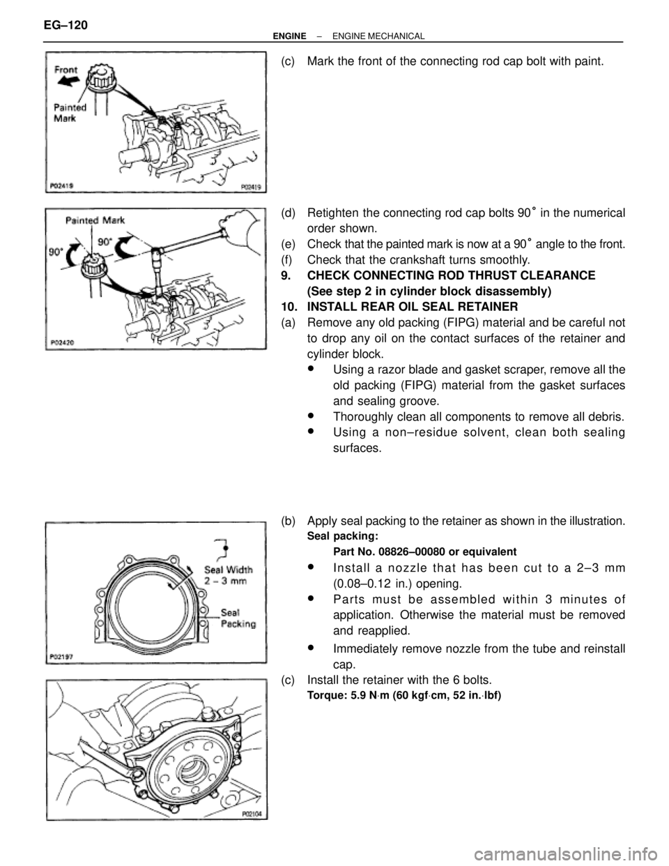
(c) Mark the front of the connecting rod cap bolt with paint.
(d) Retighten the connecting rod cap bolts 90° in the numerical
order shown.
(e) Check that the painted mark is now at a 90° angle to the front.
(f) Check that the crankshaft turns smoothly.
9. CHECK CONNECTING ROD THRUST CLEARANCE
(See step 2 in cylinder block disassembly)
10. INSTALL REAR OIL SEAL RETAINER
(a) Remove any old packing (FIPG) material and be careful not
to drop any oil on the contact surfaces of the retainer and
cylinder block.
wUsing a razor blade and gasket scraper, remove all the
old packing (FIPG) material from the gasket surfaces
and sealing groove.
wThoroughly clean all components to remove all debris.
wUsing a non±residue solvent, clean both sealing
surfaces.
(b) Apply seal packing to the retainer as shown in the illustration.
Seal packing:
Part No. 08826±00080 or equivalent
wInstall a nozzle that has been cut to a 2±3 mm
(0.08±0.12 in.) opening.
wParts must be assembled within 3 minutes of
application. Otherwise the material must be removed
and reapplied.
wImmediately remove nozzle from the tube and reinstall
cap.
(c) Install the retainer with the 6 bolts.
Torque: 5.9 NVm (60 kgfVcm, 52 in.Vlbf)
EG±120± ENGINEENGINE MECHANICAL