Page 365 of 878
VSV FOR EVAP
COMPONENTS FOR REMOVAL AND
INSTALLATION
VSV INSPECTION
1. REMOVE VSV
2. INSPECT VSV
A. Inspect VSV for open circuit
Using an ohmmeter, check that there is continuity between
the terminals.
Resistance:
At 205C (685F) 27±33 �
If there is no continuity, replace the VSV.
B. Inspect VSV for ground
Using an ohmmeter, check that there is no continuity be-
tween each terminal and the body.
If there is continuity, replace the VSV.
± ENGINESFI SYSTEM (2JZ±GE)EG±239
Page 366 of 878
C. Inspect VSV operation
(a) Check that air does not flow from port E to F.
(b) Apply battery voltage across the terminals.
(c) Check that air flows from port E to F.
If operation is not as specified, replace the VSV.
3. REINSTALL VSV
VSV FOR EGR
COMPONENTS FOR REMOVAL AND
INSTALLATION
EG±240± ENGINESFI SYSTEM (2JZ±GE)
Page 367 of 878
VSV INSPECTION
1. REMOVE VSV
2. INSPECT VSV
A. Inspect VSV for open circuit
Using an ohmmeter, check that there is continuity between
the terminals.
Resistance:
At 20°C (68°F) 38.5±44.5 �
If there is no continuity, replace the VSV.
B. Inspect VSV for ground
Using an ohmmeter, check that there is no continuity be-
tween each terminal and the body.
If there is continuity, replace the VSV.
C. Inspect VSV operation
(a) Check that air does not flow from port E to F.
(b) Apply battery voltage across the terminals.
(c) Check that air flows from port E to F.
If operation is not as specified, replace the VSV.
3. REINSTALL VSV
± ENGINESFI SYSTEM (2JZ±GE)EG±241
Page 371 of 878
KNOCK SENSOR
COMPONENTS FOR REMOVAL AND
INSTALLATION
KNOCK SENSORS INSPECTION
1. REMOVE STARTER
(See starter removal in Starting System)
2. REMOVE KNOCK SENSORS
(a) Disconnect the knock sensor connector.
(b) Using SST, remove the knock sensor.
SST 09816±30010
3. INSPECT KNOCK SENSORS
Using an ohmmeter, check that there is no continuity be-
tween the terminal and body.
If there is continuity, replace the sensor.
± ENGINESFI SYSTEM (2JZ±GE)EG±245
Page 374 of 878

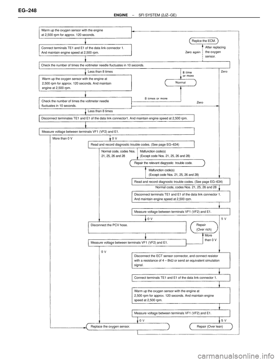
Warm up the oxygen sensor with the engine
at 2,500 rpm for approx. 120 seconds.
Connect terminals TE1 and E1 of the data link connector 1.
And maintain engine speed at 2,500 rpm.
Check the number of times the voltmeter needle fluctuates in 10 seconds.
Less than 8 times
Warm up the oxygen sensor with the engine at
2,500 rpm for approx. 120 seconds. And maintain
engine at 2,500 rpm.
Check the number of times the voltmeter needle
fluctuates in 10 seconds.
Less than 8 times
Disconnect terminates TE1 and E1 of the data link connector1. And maintain engine speed at 2,500 rpm.
Measure voltage between terminals VF1 (VF2) and E1.
More than 0 V
Read and record diagnostic trouble codes. (See page EG±634)
Normal code, codes Nos.
21, 25, 26 and 28Malfunction code(s)
(Except code Nos. 21, 25, 26 and 28)
Repair the relevant diagnostic trouble code.
Malfunction code(s)
(Except code Nos. 21, 25, 26 and 28)
Read and record diagnostic trouble codes. (See page EG±634)
Normal code, codes Nos. 21, 25, 26 and 28
Disconnect terminals TE1 and E1 of the data link connector 1.
And maintain engine speed at 2,500 rpm.
Measure voltage between terminals VF1 (VF2) and E1.
Repair
(Over rich)
More
than 0 V
Disconnect the PCV hose.
Measure voltage between terminals VF1 (VF2) and E1.
Disconnect the ECT sensor connector, and connect resistor
with a resistance of 4 ± 8k� or send an equivalent simulation
signal.
Connect terminals TE1 and E1 of the data link connector 1.
Warm up the oxygen sensor with the engine at
2,500 rpm for approx. 120 seconds. And maintain engine
speed at 2,500 rpm.
Measure voltage between terminals VF1 (VF2) and E1.
Repair (Over lean)Replace the oxygen sensor.
Replce the ECM.
After replacing
the oxygen
sensor.
EG±248± ENGINESFI SYSTEM (2JZ±GE)
Page 381 of 878
FUEL CUT RPM
FUEL CUT RPM INSPECTION
1. WARM UP ENGINE
Allow the engine to warm up to normal operating tempera-
ture.
2. CONNECT TACHOMETER TO ENGINE
Connect the tester probe of a tachometer to terminal IG� of
the DLC1.
NOTICE:
wNever allow the tachometer terminal to touch ground as
it could result in damage to the igniter and/or ignition
coil.
wAs some tachometers are not compatible with this igni-
tion system, we recommend that you confirm the compat-
ibility of your unit before use.
3. INSPECT FUEL CUTOFF OPERATION
(a) Increase the engine speed to at least 3,000 rpm.
(b) Check for injector operating noise.
(c) Check that when the throttle lever is released, injector
operation noise stops momentarily and then resumes.
HINT: Measure with the A/C OFF.
Fuel return speed:
1,400 rpm
4. DISCONNECT TACHOMETER
± ENGINESFI SYSTEM (2JZ±GE)EG±255
Page 387 of 878
(09316±00050) Replacer ªDº
09330±00021Companion Flange Holding Tool
09608±30022 Front Hub Bearing Replacer Set
(09608±05010) Handle
09816±30010 Oil Pressure Switch Socket
09843±18020 Diagnosis Check Wire
09950±50010 Puller C Set
(09951±05010)Hanger 150
(09952±05010) Slide Arm
(09953±05020) Center Bolt 150
(09954±05010)Claw No.1
(09954±05030)Claw No.3
09960±10010 Variable Pin Wrench Set
(09962±01000) Variable Pin Wrench Arm AssyCamshaft timing pulley
Camshaft pulley
Crankshaft timing pulley
Crankshaft pulley
Crankshaft timing pulley
Crankshaft pulley
Crankshaft timing pulley
Crankshaft pulley
Crankshaft timing pulley
Knock sensor
Oil pressure switch
Crankshaft rear oil seal
Valve guide bushing
Crankshaft pulley
Camshaft oil seal
EG±4± ENGINEENGINE MECHANICAL
Page 390 of 878

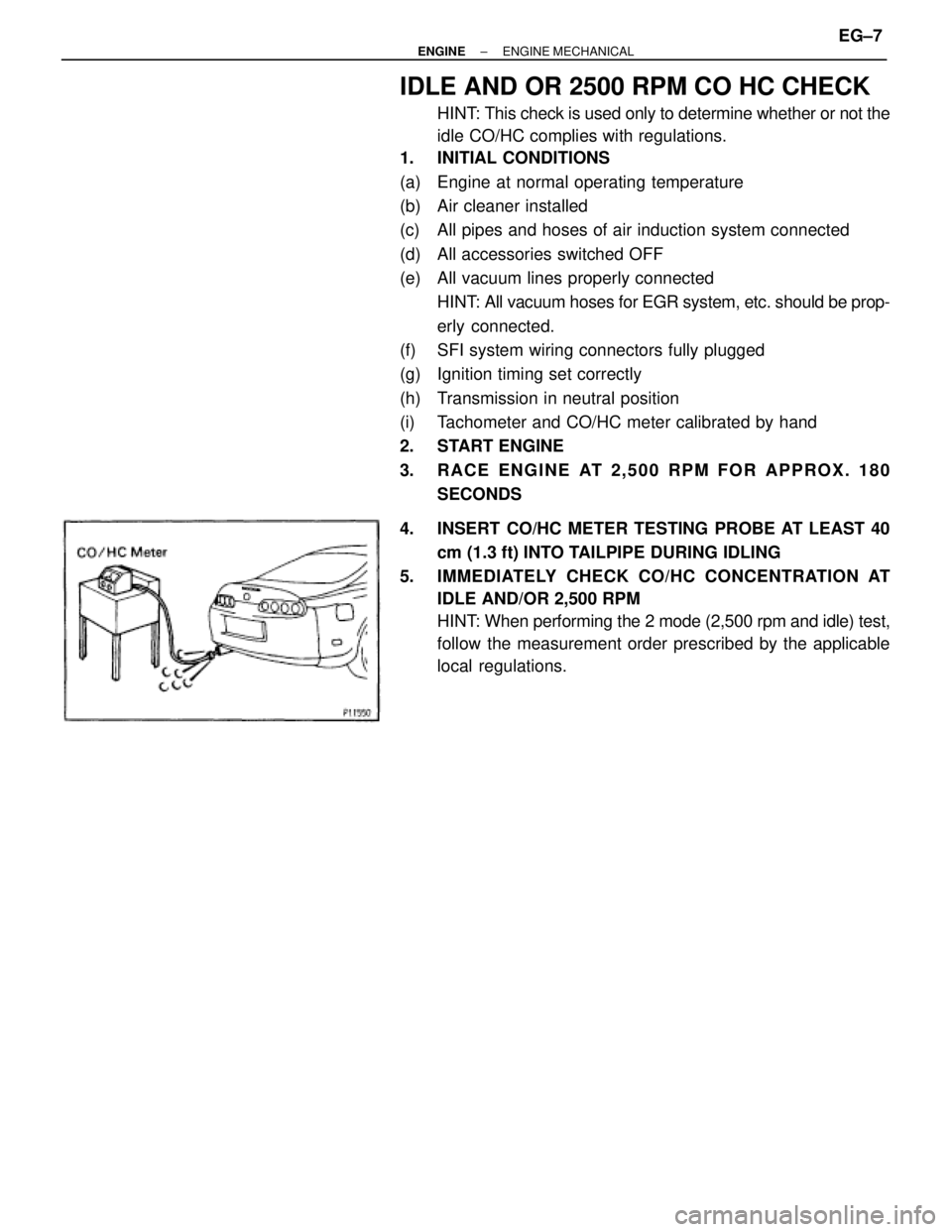
IDLE AND OR 2500 RPM CO HC CHECK
HINT: This check is used only to determine whether or not the
idle CO/HC complies with regulations.
1. INITIAL CONDITIONS
(a) Engine at normal operating temperature
(b) Air cleaner installed
(c) All pipes and hoses of air induction system connected
(d) All accessories switched OFF
(e) All vacuum lines properly connected
HINT: All vacuum hoses for EGR system, etc. should be prop-
erly connected.
(f) SFI system wiring connectors fully plugged
(g) Ignition timing set correctly
(h) Transmission in neutral position
(i) Tachometer and CO/HC meter calibrated by hand
2. START ENGINE
3. RACE ENGINE AT 2,500 RPM FOR APPROX. 180
SECONDS
4. INSERT CO/HC METER TESTING PROBE AT LEAST 40
cm (1.3 ft) INTO TAILPIPE DURING IDLING
5. IMMEDIATELY CHECK CO/HC CONCENTRATION AT
IDLE AND/OR 2,500 RPM
HINT: When performing the 2 mode (2,500 rpm and idle) test,
follow the measurement order prescribed by the applicable
local regulations.
± ENGINEENGINE MECHANICALEG±7