Page 340 of 878
FUEL PRESSURE PULSATION DAMPER
INSTALLATION
1. INSTALL FUEL PRESSURE PULSATION DAMPER
(a) Install the fuel inlet pipe and pulsation damper with 2 new
gaskets.
HINT: Different sized gaskets are used for the upper (large
size) and lower (small size).
(b) Using SST, tighten the pulsation damper.
SST 09612±24014 (09617±24011)
Torque:
41 NVm (420 kgfVcm, 30 ftVlbf)
35 NVm (350 kgfVcm, 25 ftVlbf) for SST
HINT: Use a torque wrench with a fulcrum length of 30 cm
(11.81 in.).
2. INSTALL STARTER
(See starter installation in Starting System)
4. CHECK FOR FUEL LEAKS
(See item 5 in fuel system in precaution) EG±214
± ENGINESFI SYSTEM (2JZ±GE)
Page 342 of 878
PRECAUTIONS
1. Always use new gaskets when replacing the fuel tank or
component parts.
2. Apply the proper torque to all parts tightened.
FUEL LINES AND CONNECTIONS
INSPECTION
(a) Check the fuel lines for cracks or leakage, and all
connections for deformation.
(b) C h e c k t h e f u e l t a n k vapor vent system hoses and
connections for looseness, sharp bends or damage.
(c) Check the fuel tank for deformation, cracks, fuel leakage or
tank band looseness.
(d) Check the filler neck for damage or fuel leakage.
(e) Hose and tube connections are as shown in the illustration.
If a problem is found, repair or replace the part as necessary. EG±216
± ENGINESFI SYSTEM (2JZ±GE)
Page 344 of 878
VAF METER REMOVAL
Installation is in the reverse order of removal.
1. REMOVE INTAKE AIR CONNECTOR PIPE
(a) Disconnect these hoses:
(1) PS air hose from air connector pipe
(2) PCV hose from No.2 cylinder head cover
(b) Loosen the 2 hose clamps, and remove the air connector
pipe together with the hoses.
2. REMOVE VAF METER
(a) Disconnect the VAF meter connector.
(b) Disconnect the VAF meter wire from the wire clamp on the
bracket.
(c) Remove the 4 nuts, bolt, VAF meter and gasket.
Torque: 10 NVm (100 kgfVcm, 7 ftVlbf)
VAF METER INSPECTION
INSPECT VAF METER
Check that the honeycomb is neither deformed nor dam-
aged.
If necessary, replace the VAF meter. EG±218
± ENGINESFI SYSTEM (2JZ±GE)
Page 345 of 878

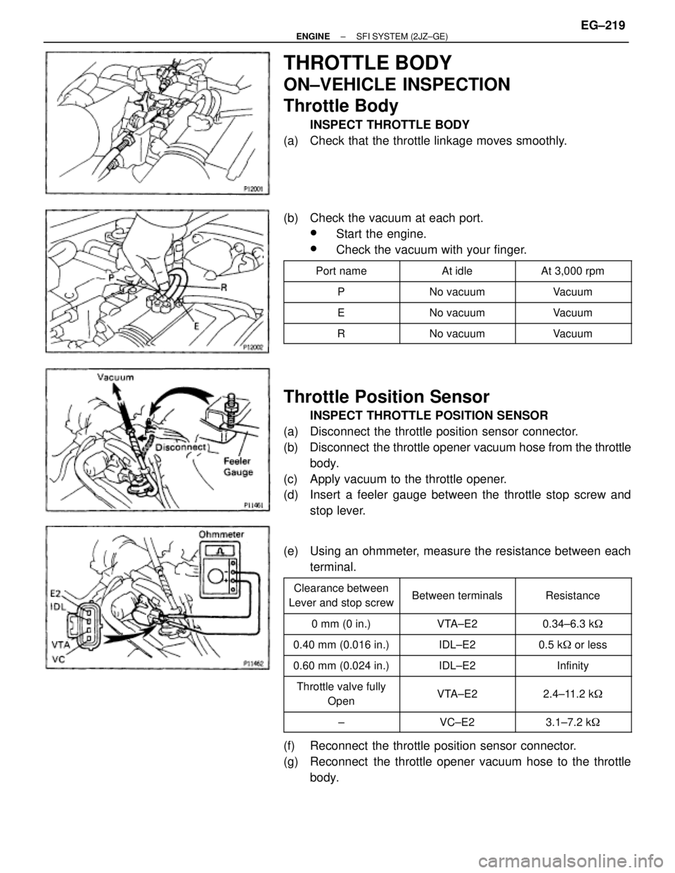
THROTTLE BODY
ON±VEHICLE INSPECTION
Throttle Body
INSPECT THROTTLE BODY
(a) Check that the throttle linkage moves smoothly.
(b) Check the vacuum at each port.
wStart the engine.
wCheck the vacuum with your finger.
�������� ��������Port name�������� ��������At idle�������� ��������At 3,000 rpm
�������� ��������P�������� ��������No vacuum�������� ��������Vacuum�������� �
������� ��������E
�������� �
������� ��������No vacuum
�������� �
������� ��������Vacuum
�������� ��������R�������� ��������No vacuum�������� ��������Vacuum
Throttle Position Sensor
INSPECT THROTTLE POSITION SENSOR
(a) Disconnect the throttle position sensor connector.
(b) Disconnect the throttle opener vacuum hose from the throttle
body.
(c) Apply vacuum to the throttle opener.
(d) Insert a feeler gauge between the throttle stop screw and
stop lever.
(e) Using an ohmmeter, measure the resistance between each
terminal.
�������� �
������� ��������
Clearance between
Lever and stop screw�������� �
������� ��������Between terminals�������� �
������� ��������Resistance
�������� ��������0 mm (0 in.)�������� ��������VTA±E2�������� ��������0.34±6.3 k�
�������� ��������0.40 mm (0.016 in.)�������� ��������IDL±E2�������� ��������0.5 k� or less
�������� ��������0.60 mm (0.024 in.)�������� ��������IDL±E2�������� ��������Infinity�������� �
������� �
������� ��������
Throttle valve fully
Open
�������� �
������� �
������� ��������
VTA±E2
�������� �
������� �
������� ��������
2.4±11.2 k�
�������� ��������±�������� ��������VC±E2�������� ��������3.1±7.2 k�
(f) Reconnect the throttle position sensor connector.
(g) Reconnect the throttle opener vacuum hose to the throttle
body.
± ENGINESFI SYSTEM (2JZ±GE)EG±219
Page 346 of 878

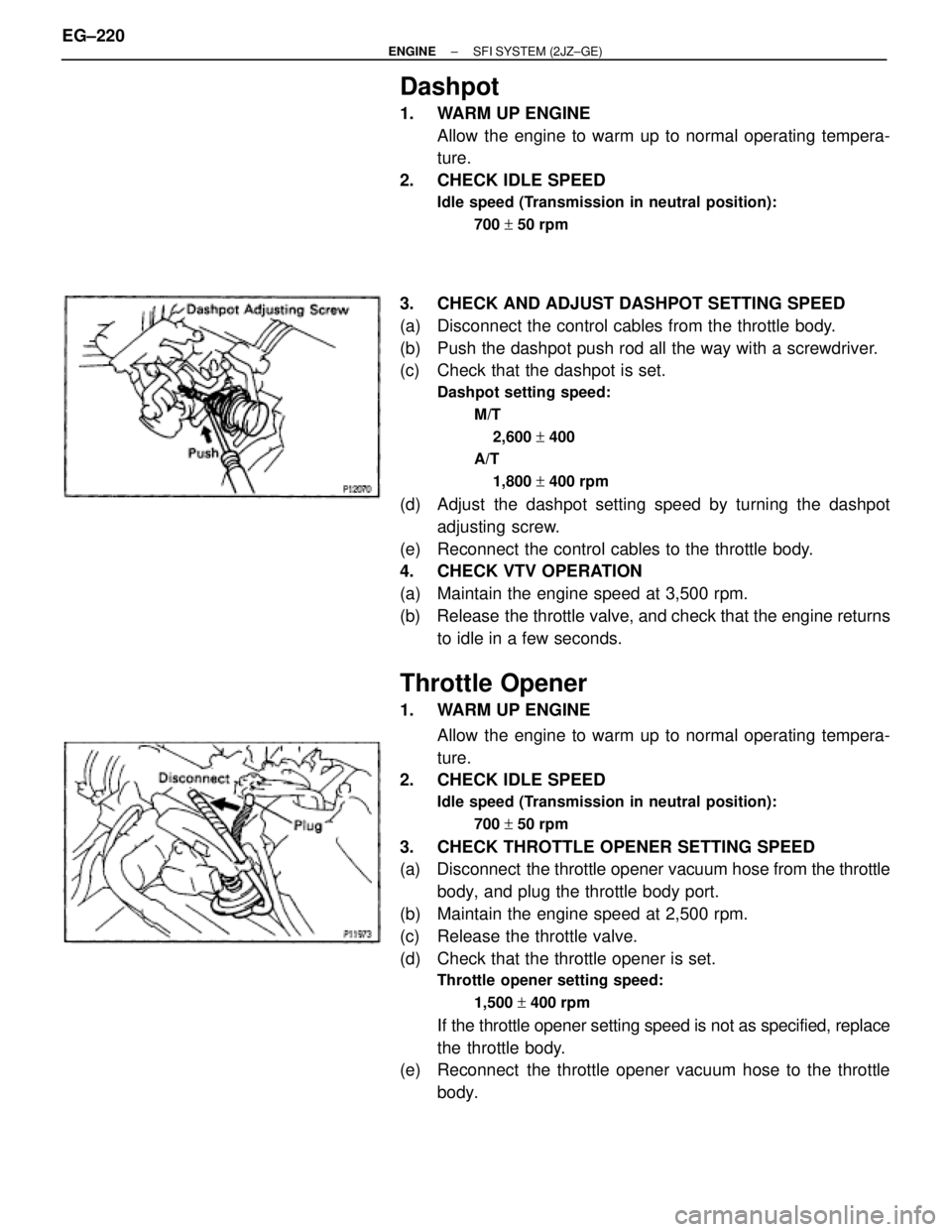
Dashpot
1. WARM UP ENGINE
Allow the engine to warm up to normal operating tempera-
ture.
2. CHECK IDLE SPEED
Idle speed (Transmission in neutral position):
700 + 50 rpm
3. CHECK AND ADJUST DASHPOT SETTING SPEED
(a) Disconnect the control cables from the throttle body.
(b) Push the dashpot push rod all the way with a screwdriver.
(c) Check that the dashpot is set.
Dashpot setting speed:
M/T
2,600 + 400
A/T
1,800 + 400 rpm
(d) Adjust the dashpot setting speed by turning the dashpot
adjusting screw.
(e) Reconnect the control cables to the throttle body.
4. CHECK VTV OPERATION
(a) Maintain the engine speed at 3,500 rpm.
(b) Release the throttle valve, and check that the engine returns
to idle in a few seconds.
Throttle Opener
1. WARM UP ENGINE
Allow the engine to warm up to normal operating tempera-
ture.
2. CHECK IDLE SPEED
Idle speed (Transmission in neutral position):
700 + 50 rpm
3. CHECK THROTTLE OPENER SETTING SPEED
(a) Disconnect the throttle opener vacuum hose from the throttle
body, and plug the throttle body port.
(b) Maintain the engine speed at 2,500 rpm.
(c) Release the throttle valve.
(d) Check that the throttle opener is set.
Throttle opener setting speed:
1,500 + 400 rpm
If the throttle opener setting speed is not as specified, replace
the throttle body.
(e) Reconnect the throttle opener vacuum hose to the throttle
body. EG±220
± ENGINESFI SYSTEM (2JZ±GE)
Page 349 of 878

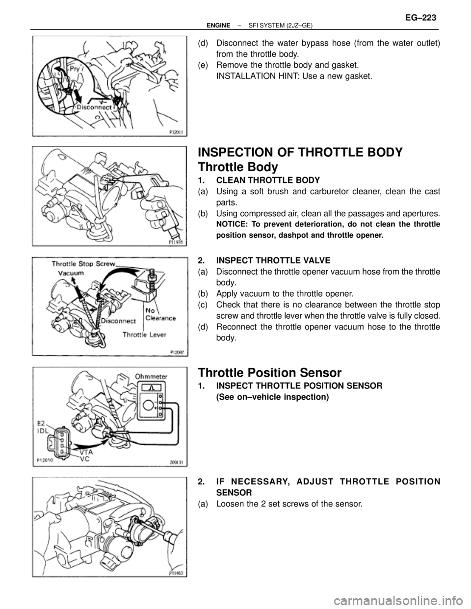
(d) Disconnect the water bypass hose (from the water outlet)
from the throttle body.
(e) Remove the throttle body and gasket.
INSTALLATION HINT: Use a new gasket.
INSPECTION OF THROTTLE BODY
Throttle Body
1. CLEAN THROTTLE BODY
(a) Using a soft brush and carburetor cleaner, clean the cast
parts.
(b) Using compressed air, clean all the passages and apertures.
NOTICE: To prevent deterioration, do not clean the throttle
position sensor, dashpot and throttle opener.
2. INSPECT THROTTLE VALVE
(a) Disconnect the throttle opener vacuum hose from the throttle
body.
(b) Apply vacuum to the throttle opener.
(c) Check that there is no clearance between the throttle stop
screw and throttle lever when the throttle valve is fully closed.
(d) Reconnect the throttle opener vacuum hose to the throttle
body.
Throttle Position Sensor
1. INSPECT THROTTLE POSITION SENSOR
(See on±vehicle inspection)
2. IF NECESSARY, ADJUST THROTTLE POSITION
SENSOR
(a) Loosen the 2 set screws of the sensor.
± ENGINESFI SYSTEM (2JZ±GE)EG±223
Page 350 of 878
(b) Insert a 0.50 mm (0.020 in.) feeler gauge between the throttle
stop screw and stop lever.
(c) Connect the tester probe of an ohmmeter to the terminals IDL
and E2 of the sensor.
(d) Gradually turn the sensor clockwise until the ohmmeter
deflects, and secure it with the 2 set screws.
(e) Recheck the continuity between terminals IDL and E2.
����������� �
���������� �
���������� �����������
Clearance between
lever and stop screw
������������ �
����������� �
����������� ������������
Continuity (IDL±E2)
����������� �����������0.40 mm (0.016 in.)������������ ������������Continuity
����������� �����������0.60 mm (0.024 in.)������������ ������������No continuity
EG±224± ENGINESFI SYSTEM (2JZ±GE)
Page 351 of 878
IDLE AIR CONTROL (IAC) VALVE
ON±VEHICLE INSPECTION
1. INSPECT IAC VALVE FOR OPERATING SOUND
Check that there is a clicking sound immediately after stop-
ping the engine.
If operation is not as specified, check the IAC valve, wiring
and ECM.
2. California only:
INSPECT AIR ASSIST SYSTEM
A. Warm up engine
Allow the engine to warm up to normal operating tempera-
ture.
B. Check idle speed
Idle speed (Transmission in neutral position):
700 + 50 rpm
C. Check IAC valve operation
With engine idling, pinch the air hose and check that engine
speed drops, and then returns back up to idle speed.
If operation is not as specified, check the IAC valve, wiring
and ECM.
3. INSPECT IAC VALVE RESISTANCE
Using an ohmmeter, measure the resistance between the ter-
minals (B1 (or B2) to others).
Resistance:
At 20°C (68°F) 18±22 �
If the resistance is not as specified, replace the IAC valve.
± ENGINESFI SYSTEM (2JZ±GE)EG±225