Page 320 of 878

(h) Reconnect the negative (±) terminal cable to the battery.
(i) Turn the ignition switch ON.
(j) Measure the fuel pressure.
Fuel pressure:
265±304 kPa (2.7±3.1 kgf/cm
2, 38±44 psi)
If pressure is high, replace the fuel pressure regulator.
If pressure is low, check the following parts:
wFuel hoses and connections
wFuel pump
wFuel filter
wFuel pressure regulator
(k) Remove the SST from the DLC1.
SST 09843±18020
(l) Start the engine.
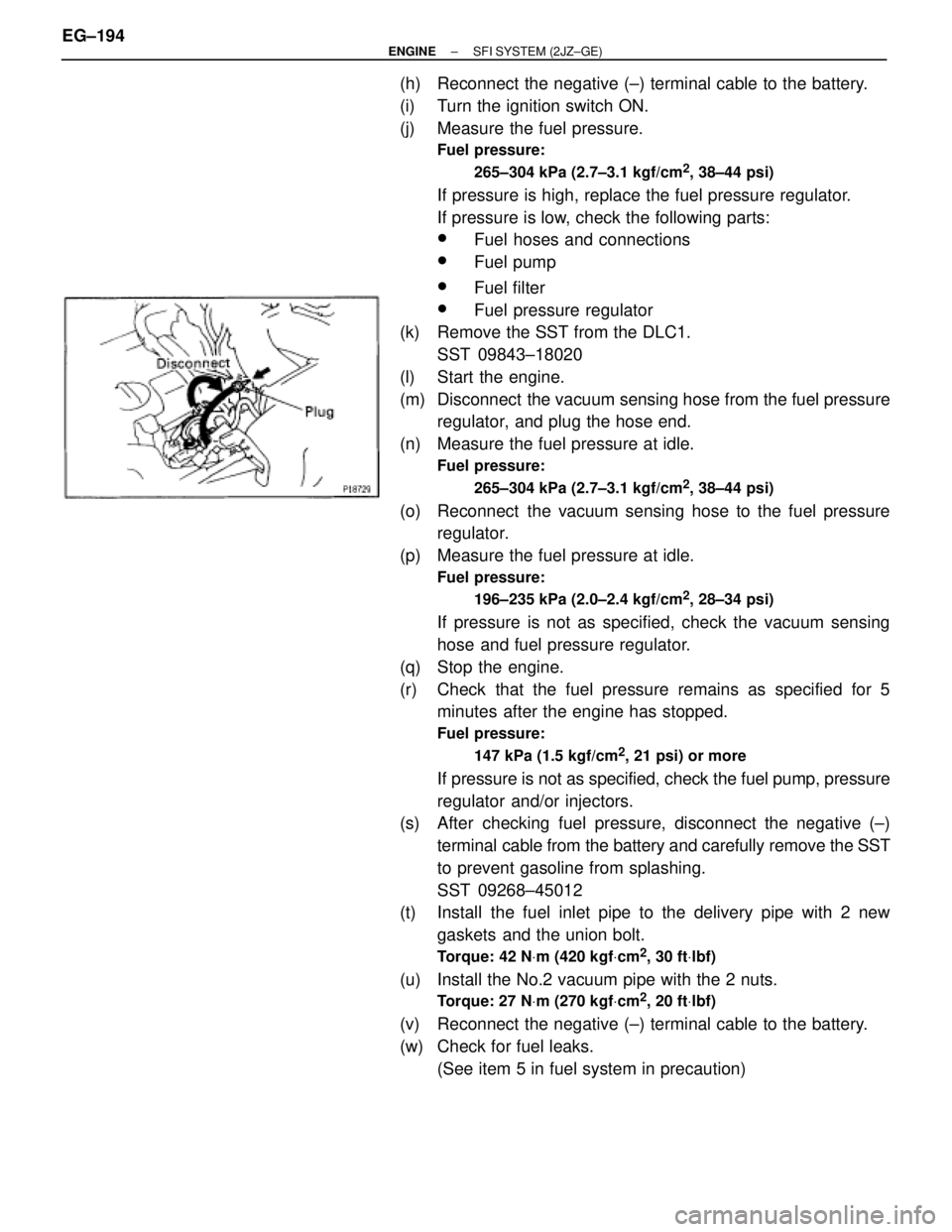
(m) Disconnect the vacuum sensing hose from the fuel pressure
regulator, and plug the hose end.
(n) Measure the fuel pressure at idle.
Fuel pressure:
265±304 kPa (2.7±3.1 kgf/cm
2, 38±44 psi)
(o) Reconnect the vacuum sensing hose to the fuel pressure
regulator.
(p) Measure the fuel pressure at idle.
Fuel pressure:
196±235 kPa (2.0±2.4 kgf/cm
2, 28±34 psi)
If pressure is not as specified, check the vacuum sensing
hose and fuel pressure regulator.
(q) Stop the engine.
(r) Check that the fuel pressure remains as specified for 5
minutes after the engine has stopped.
Fuel pressure:
147 kPa (1.5 kgf/cm
2, 21 psi) or more
If pressure is not as specified, check the fuel pump, pressure
regulator and/or injectors.
(s) After checking fuel pressure, disconnect the negative (±)
terminal cable from the battery and carefully remove the SST
to prevent gasoline from splashing.
SST 09268±45012
(t) Install the fuel inlet pipe to the delivery pipe with 2 new
gaskets and the union bolt.
Torque: 42 NVm (420 kgfVcm2, 30 ftVlbf)
(u) Install the No.2 vacuum pipe with the 2 nuts.
Torque: 27 NVm (270 kgfVcm2, 20 ftVlbf)
(v) Reconnect the negative (±) terminal cable to the battery.
(w) Check for fuel leaks.
(See item 5 in fuel system in precaution) EG±194
± ENGINESFI SYSTEM (2JZ±GE)
Page 324 of 878
(b) Pull out the lower side of the fuel pump from the pump
bracket.
(c) Remove the rubber cushion from the fuel pump.
(d) Disconnect the fuel hose from the fuel pump, and remove the
fuel pump.
3. REMOVE FUEL PUMP FILTER FROM FUEL PUMP
(a) Using a small screwdriver, remove the clip.
INSTALLATION HINT: Use a new clip.
(b) Pull out the pump filter.
FUEL PUMP INSTALLATION
1. INSTALL FUEL PUMP AND SENDER GAUGE ASSEMBLY
(a) Install a new gasket to the fuel tank.
(b) Insert fuel pump and sender gauge assembly into the fuel
tank.
(c) Align the arrow marks of the fuel pump bracket and fuel tank.
(d) Temporarily install the retainer.
(e) Using SST, tighten the retainer until the arrow mark on the
retainer is within the lines on the fuel tank.
SST 09808±14010
(f) Check that the arrow marks of the fuel pump bracket and fuel
tank are aligned. EG±198
± ENGINESFI SYSTEM (2JZ±GE)
Page 325 of 878
(g) Install the retainer clamp.
(h) Connect the connector and hoses to the fuel pump bracket:
wFuel pump connector
wFuel outlet hose
Connect the outlet hose with 2 new gaskets and the union
bolt.
Torque: 29 NVm (300 kgfVcm, 22 ftVlbf)
wFuel return hose
wFuel breather hose
2. REMOVE SERVICE HOLE COVER
3. REMOVE SPARE WHEEL
4. REMOVE SPARE WHEEL COVER
5. TAKE OUT FLOOR CARPET
6. CHECK FOR FUEL LEAKS
(See item 5 in fuel system in precaution)
± ENGINESFI SYSTEM (2JZ±GE)EG±199
Page 327 of 878
FUEL PRESSURE REGULATOR
INSTALLATION
1. INSTALL FUEL PRESSURE REGULATOR
(a) Apply a light coat of gasoline to a new O±ring, and install it
to the pressure regulator.
(b) Attach the pressure regulator to the delivery pipe.
(c) Check that the pressure regulator rotates smoothly.
NOTICE: If it does not rotate smoothly, the O±ring may be
pinched, so remove the pressure regulator and do steps (b)
and (c) above again.
(d) Install the pressure regulator with the 2 bolts.
Torque: 8.8 NVm (90 kgfVcm, 78 in.Vlbf)
2. CONNECT FUEL RETURN PIPE TO FUEL PRESSURE
REGULATOR
Install the return pipe with 2 new gaskets and the union bolt.
Torque: 27 NVm (280 kgfVcm, 20 ftVlbf)
3. CONNECT VACUUM SENSING HOSE TO FUEL
PRESSURE REGULATOR
4. CHECK FOR FUEL LEAKS
(See item 5 in fuel system in precaution)
± ENGINESFI SYSTEM (2JZ±GE)EG±201
Page 328 of 878

INJECTOR
ON±VEHICLE INSPECTION
1. INSPECT INJECTOR OPERATION
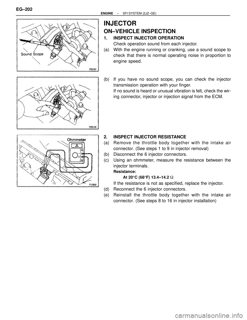
Check operation sound from each injector.
(a) With the engine running or cranking, use a sound scope to
check that there is normal operating noise in proportion to
engine speed.
(b) If you have no sound scope, you can check the injector
transmission operation with your finger.
If no sound is heard or unusual vibration is felt, check the wir-
ing connector, injector or injection signal from the ECM.
2. INSPECT INJECTOR RESISTANCE
(a) Re mo ve th e th ro ttle bo d y together with the intake air
connector. (See steps 1 to 9 in injector removal)
(b) Disconnect the 6 injector connectors.
(c) Using an ohmmeter, measure the resistance between the
injector terminals.
Resistance:
At 205C (685F) 13.4±14.2 �
If the resistance is not as specified, replace the injector.
(d) Reconnect the 6 injector connectors.
(e) Reinstall the throttle body together with the intake air
connector. (See steps 8 to 16 in injector installation) EG±202
± ENGINESFI SYSTEM (2JZ±GE)
Page 335 of 878

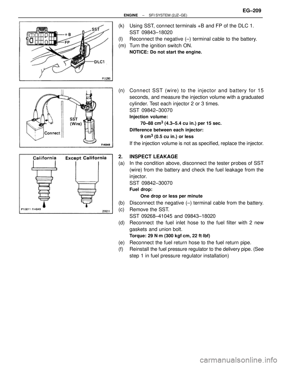
(k) Using SST, connect terminals +B and FP of the DLC 1.
SST 09843±18020
(l) Reconnect the negative (±) terminal cable to the battery.
(m) Turn the ignition switch ON.
NOTICE: Do not start the engine.
(n) Connect SST (wire) to the injector and battery for 15
seconds, and measure the injection volume with a graduated
cylinder. Test each injector 2 or 3 times.
SST 09842±30070
Injection volume:
70±88 cm
3 (4.3±5.4 cu in.) per 15 sec.
Difference between each injector:
9 cm
3 (0.5 cu in.) or less
If the injection volume is not as specified, replace the injector.
2. INSPECT LEAKAGE
(a) In the condition above, disconnect the tester probes of SST
(wire) from the battery and check the fuel leakage from the
injector.
SST 09842±30070
Fuel drop:
One drop or less per minute
(b) Disconnect the negative (±) terminal cable from the battery.
(c) Remove the SST.
SST 09268±41045 and 09843±18020
(d) Reconnect the fuel inlet hose to the fuel filter with 2 new
gaskets and union bolt.
Torque: 29 NVm (300 kgfVcm, 22 ftVlbf)
(e) Reconnect the fuel return hose to the fuel return pipe.
(f) Reinstall the fuel pressure regulator to the delivery pipe. (See
step 1 in fuel pressure regulator installation)
± ENGINESFI SYSTEM (2JZ±GE)EG±209
Page 337 of 878

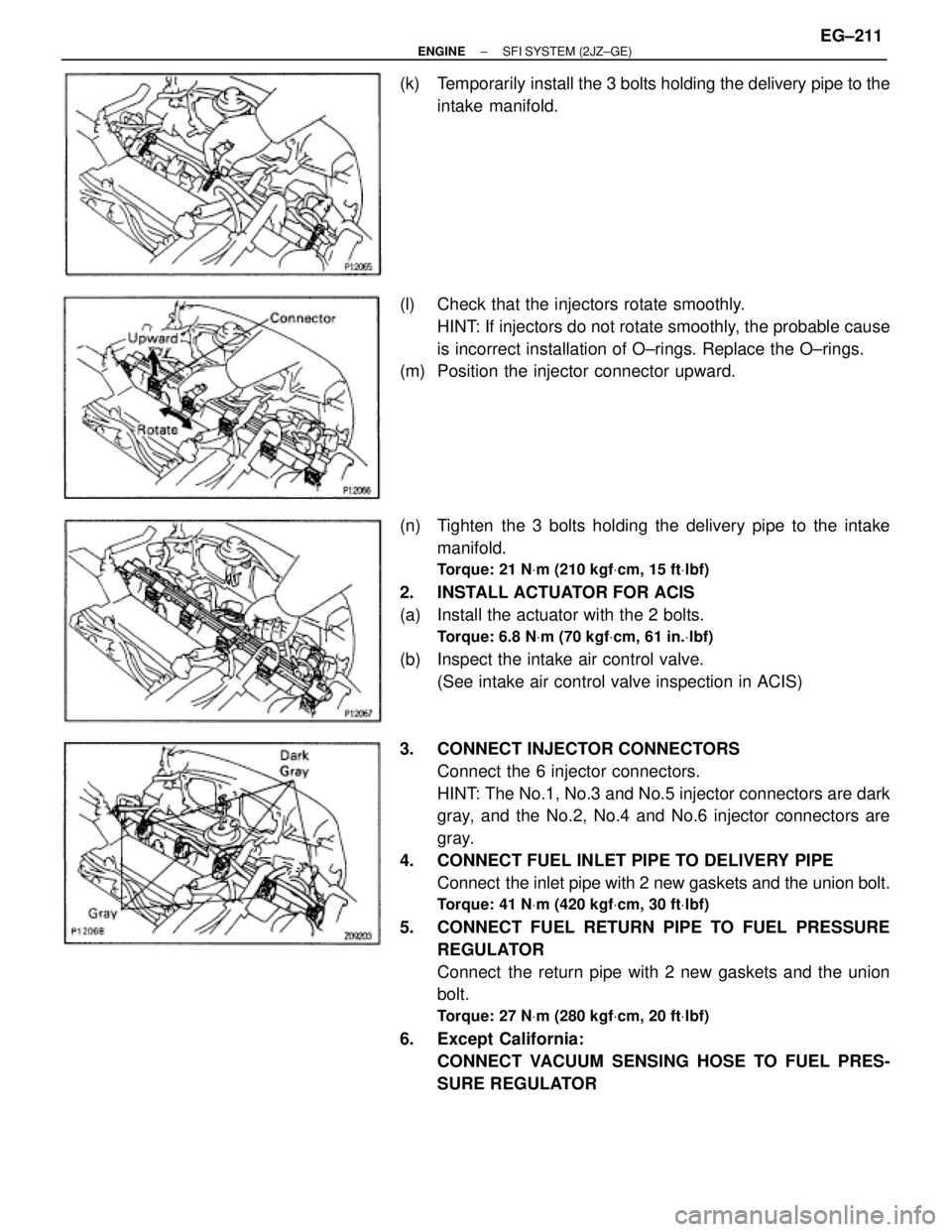
(k) Temporarily install the 3 bolts holding the delivery pipe to the
intake manifold.
(l) Check that the injectors rotate smoothly.
HINT: If injectors do not rotate smoothly, the probable cause
is incorrect installation of O±rings. Replace the O±rings.
(m) Position the injector connector upward.
(n) Tighten the 3 bolts holding the delivery pipe to the intake
manifold.
Torque: 21 NVm (210 kgfVcm, 15 ftVlbf)
2. INSTALL ACTUATOR FOR ACIS
(a) Install the actuator with the 2 bolts.
Torque: 6.8 NVm (70 kgfVcm, 61 in.Vlbf)
(b) Inspect the intake air control valve.
(See intake air control valve inspection in ACIS)
3. CONNECT INJECTOR CONNECTORS
Connect the 6 injector connectors.
HINT: The No.1, No.3 and No.5 injector connectors are dark
gray, and the No.2, No.4 and No.6 injector connectors are
gray.
4. CONNECT FUEL INLET PIPE TO DELIVERY PIPE
Connect the inlet pipe with 2 new gaskets and the union bolt.
Torque: 41 NVm (420 kgfVcm, 30 ftVlbf)
5. CONNECT FUEL RETURN PIPE TO FUEL PRESSURE
REGULATOR
Connect the return pipe with 2 new gaskets and the union
bolt.
Torque: 27 NVm (280 kgfVcm, 20 ftVlbf)
6. Except California:
CONNECT VACUUM SENSING HOSE TO FUEL PRES-
SURE REGULATOR
± ENGINESFI SYSTEM (2JZ±GE)EG±211
Page 339 of 878
Torque: 64 NVm (650 kgfVcm, 47 ftVlbf)
13. California only:
INSTALL VSV FOR FUEL PRESSURE CONTROL
14. INSTALL INTAKE AIR CONNECTOR PIPE
15. CONNECT CONTROL CABLES TO THROTTLE BODY
16. FILL WITH ENGINE COOLANT
17. CHECK FOR FUEL LEAKS
(See item 5 in fuel system in precaution)
FUEL PRESSURE PULSATION DAMPER
COMPONENTS FOR REMOVAL AND
INSTALLATION
FUEL PRESSURE PULSATION DAMPER
REMOVAL
1. REMOVE STARTER
(See starter removal in Starting System)
2. REMOVE FUEL PRESSURE PULSATION DAMPER
(a) Remove the pulsation damper and upper gasket.
(b) Disconnect the fuel inlet pipe from the fuel pipe support, and
remove the lower gasket.
± ENGINESFI SYSTEM (2JZ±GE)EG±213