Page 438 of 878
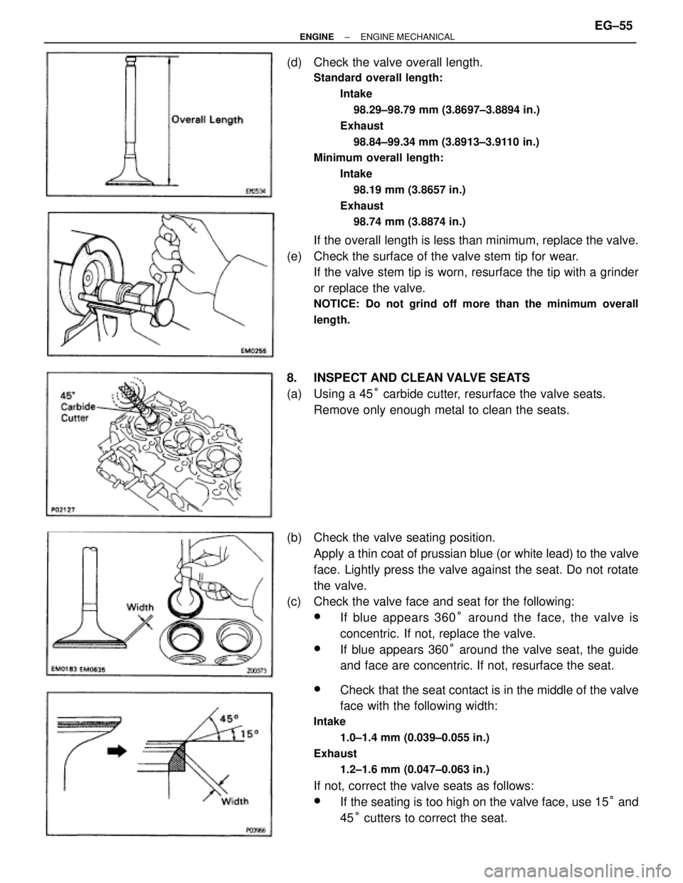
(d) Check the valve overall length.
Standard overall length:
Intake
98.29±98.79 mm (3.8697±3.8894 in.)
Exhaust
98.84±99.34 mm (3.8913±3.9110 in.)
Minimum overall length:
Intake
98.19 mm (3.8657 in.)
Exhaust
98.74 mm (3.8874 in.)
If the overall length is less than minimum, replace the valve.
(e) Check the surface of the valve stem tip for wear.
If the valve stem tip is worn, resurface the tip with a grinder
or replace the valve.
NOTICE: Do not grind off more than the minimum overall
length.
8. INSPECT AND CLEAN VALVE SEATS
(a) Using a 45° carbide cutter, resurface the valve seats.
Remove only enough metal to clean the seats.
(b) Check the valve seating position.
Apply a thin coat of prussian blue (or white lead) to the valve
face. Lightly press the valve against the seat. Do not rotate
the valve.
(c) Check the valve face and seat for the following:
wIf blue appears 360° around the face, the valve is
concentric. If not, replace the valve.
wIf blue appears 360° around the valve seat, the guide
and face are concentric. If not, resurface the seat.
wCheck that the seat contact is in the middle of the valve
face with the following width:
Intake
1.0±1.4 mm (0.039±0.055 in.)
Exhaust
1.2±1.6 mm (0.047±0.063 in.)
If not, correct the valve seats as follows:
wIf the seating is too high on the valve face, use 15° and
45° cutters to correct the seat.
± ENGINEENGINE MECHANICALEG±55
Page 440 of 878
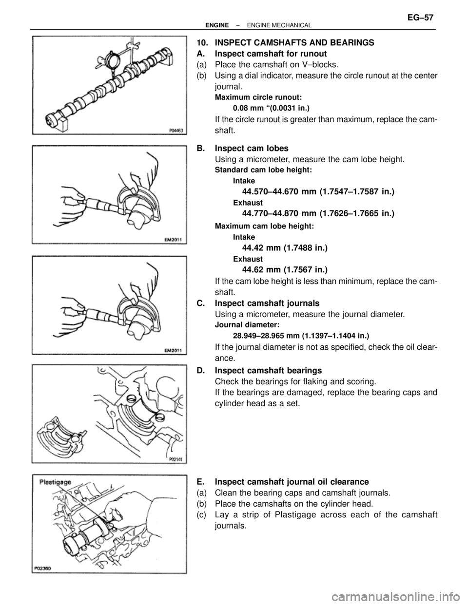
10. INSPECT CAMSHAFTS AND BEARINGS
A. Inspect camshaft for runout
(a) Place the camshaft on V±blocks.
(b) Using a dial indicator, measure the circle runout at the center
journal.
Maximum circle runout:
0.08 mm ª(0.0031 in.)
If the circle runout is greater than maximum, replace the cam-
shaft.
B. Inspect cam lobes
Using a micrometer, measure the cam lobe height.
Standard cam lobe height:
Intake
44.570±44.670 mm (1.7547±1.7587 in.)
Exhaust
44.770±44.870 mm (1.7626±1.7665 in.)
Maximum cam lobe height:
Intake
44.42 mm (1.7488 in.)
Exhaust
44.62 mm (1.7567 in.)
If the cam lobe height is less than minimum, replace the cam-
shaft.
C. Inspect camshaft journals
Using a micrometer, measure the journal diameter.
Journal diameter:
28.949±28.965 mm (1.1397±1.1404 in.)
If the journal diameter is not as specified, check the oil clear-
ance.
D. Inspect camshaft bearings
Check the bearings for flaking and scoring.
If the bearings are damaged, replace the bearing caps and
cylinder head as a set.
E. Inspect camshaft journal oil clearance
(a) Clean the bearing caps and camshaft journals.
(b) Place the camshafts on the cylinder head.
(c) Lay a strip of Plastigage across each of the camshaft
journals.
± ENGINEENGINE MECHANICALEG±57
Page 444 of 878
(b) Install these parts:
(1) Valve
(2) Spring seat
(3) Valve spring
(4) Spring retainer
HINT: Install the valve spring, facing the painted mark up-
ward.
(c) Using SST, compress the valve spring and place the 2
keepers around the valve stem.
SST 09202±70010
(d) Using a plastic±faced hammer, lightly tap the valve stem tip
to ensure a proper fit.
3. INSTALL VALVE LIFTERS AND SHIMS
(a) Install the valve lifter and shim.
(b) Check that the valve lifter rotates smoothly by hand.
4. INSTALL EGR COOLER
Install a new gasket and the EGR cooler with the 8 bolts.
Torque: 8.8 NVm (90 kgfVcm, 78 in.Vlbf)
5. 2JZ±GE:
INSTALL ECT SENSOR AND SENDER GAUGE
Torque: 20 NVm (200 kgfVcm, 14 ftVlbf)
6. 2JZ±GE:
INSTALL GROUND STRAP AND THROTTLE CABLE
BRACKET
7. 2JZ±GE:
INSTALL ENGINE HANGERS
Torque: 39 NVm (400 kgfVcm, 29 ftVlbf)
± ENGINEENGINE MECHANICALEG±61
Page 446 of 878
(e) Retighten the cylinder head bolts by 90° in the numerical
order shown in the illustration on previous page.
(f) Retighten cylinder head bolts by an additional 90° shown in
the illustration on previous page.
(g) Check that the painted mark is now turned to the rear.
2. INSTALL CAMSHAFTS
(a) Apply engine oil to the thrust portion of the camshaft.
(b) Place the camshaft on the cylinder head with the cam lobe
facing up as shown.
(c) Place the No.3 and No.7 bearing caps in their proper
location.
(d) Apply a light coat of engine oil on the threads and under the
heads of the bearing cap bolts.
(e) Temporarily tighten these bearing cap bolts uniformly and
alternately, in several passes, until the bearing caps are snug
with the cylinder head.
(f) Apply MP grease to a new camshaft oil seal lip.
± ENGINEENGINE MECHANICALEG±63
Page 448 of 878
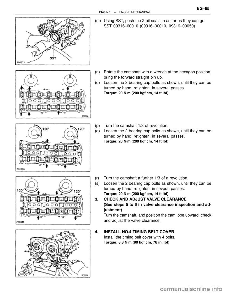
(m) Using SST, push the 2 oil seals in as far as they can go.
SST 09316±60010 (09316±00010, 09316±00050)
(n) Rotate the camshaft with a wrench at the hexagon position,
bring the forward straight pin up.
(o) Loosen the 3 bearing cap bolts as shown, until they can be
turned by hand; retighten, in several passes.
Torque: 20 NVm (200 kgfVcm, 14 ftVlbf)
(p) Turn the camshaft 1/3 of revolution.
(q) Loosen the 2 bearing cap bolts as shown, until they can be
turned by hand; retighten, in several passes.
Torque: 20 NVm (200 kgfVcm, 14 ftVlbf)
(r) Turn the camshaft a further 1/3 of a revolution.
(s) Loosen the 2 bearing cap bolts as shown, until they can be
turned by hand; retighten, in several passes.
Torque: 20 NVm (200 kgfVcm, 14 ftVlbf)
3. CHECK AND ADJUST VALVE CLEARANCE
(See steps 5 to 6 in valve clearance inspection and ad-
justment)
Turn the camshaft, and position the cam lobe upward, check
and adjust the valve clearance.
4. INSTALL NO.4 TIMING BELT COVER
Install the timing belt cover with 4 bolts.
Torque: 8.8 NVm (90 kgfVcm, 78 in.Vlbf)
± ENGINEENGINE MECHANICALEG±65
Page 452 of 878
33. INSTALL NO.2 FRONT EXHAUST PIPE
(See step 6 in engine installation in Engine Mechanical)
34. INSTALL DRIVE BELT
35. INSTALL AIR CLEANER, VAF METER AND INTAKE AIR
CONNECTOR PIPE ASSEMBLY
(See step 22 in engine installation in Engine Mechanical)
36. INSTALL AIR CLEANER DUCT
37. FILL WITH ENGINE COOLANT
38. START ENGINE AND CHECK FOR LEAKS
39. CHECK IGNITION TIMING
(See steps 8 to 12 in distributor installation in Ignition
System)
40. INSTALL ENGINE UNDER COVER
41. PERFORM ROAD TEST
Check for abnormal noise, shock, slippage, correct shift
points and smooth operation.
42. RECHECK ENGINE COOLANT LEVEL
CYLINDER HEAD INSTALLATION
(2JZ±GTE)
1. INSTALL CYLINDER HEAD
(See step 1 in cylinder head installation (2JZ±GE))
2. INSTALL CAMSHAFTS
(See step 2 ((a) to (m)) in cylinder head installation (2JZ±
GE))
3. CHECK AND ADJUST VALVE CLEARANCE
(See steps 5 to 6 in valve clearance inspection and ad-
justment)
Turn the camshaft, and position the cam lobe upward, check
and adjust the valve clearance.
4. INSTALL NO.4 TIMING BELT COVER
(See step 4 in cylinder head installation (2JZ±GE))
5. INSTALL CAMSHAFT TIMING PULLEYS
(See step 5 in cylinder head installation (2JZ±GE))
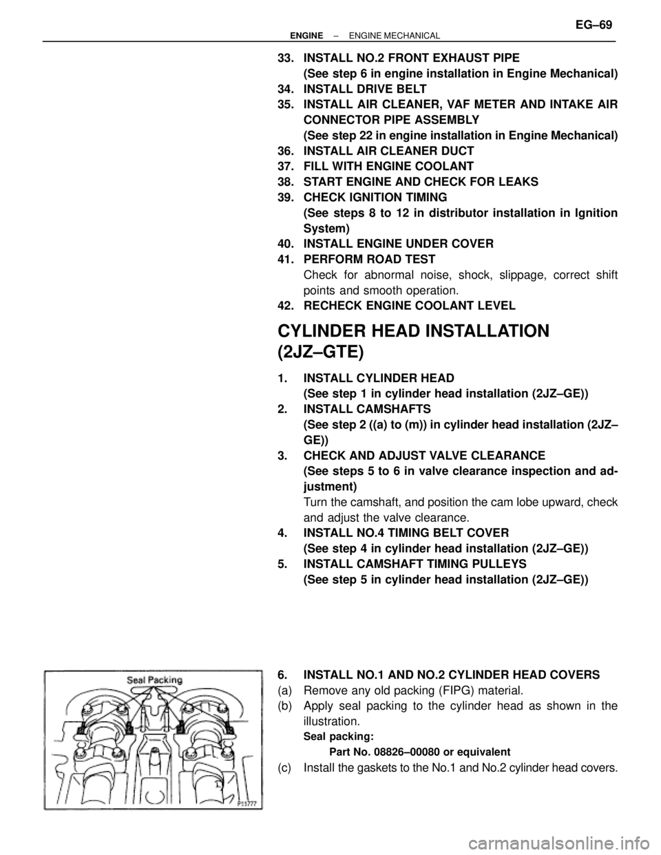
6. INSTALL NO.1 AND NO.2 CYLINDER HEAD COVERS
(a) Remove any old packing (FIPG) material.
(b) Apply seal packing to the cylinder head as shown in the
illustration.
Seal packing:
Part No. 08826±00080 or equivalent
(c) Install the gaskets to the No.1 and No.2 cylinder head covers.
± ENGINEENGINE MECHANICALEG±69
Page 482 of 878
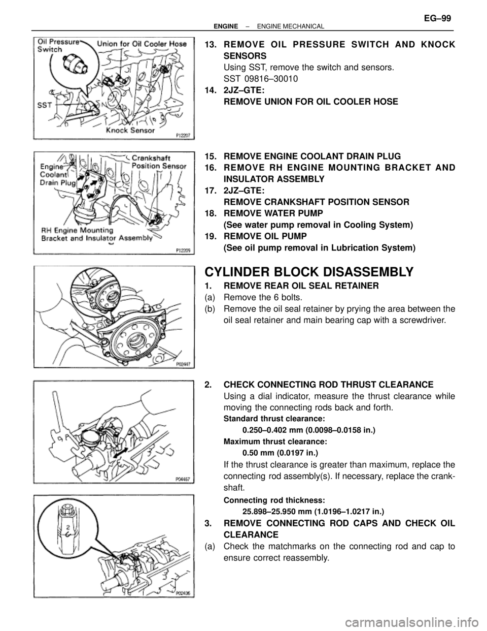
13. REMOVE OIL PRESSURE SWITCH AND KNOCK
SENSORS
Using SST, remove the switch and sensors.
SST 09816±30010
14. 2JZ±GTE:
REMOVE UNION FOR OIL COOLER HOSE
15. REMOVE ENGINE COOLANT DRAIN PLUG
16. R E M O V E R H E N G I N E M O U N T I N G B R A C K E T A N D
INSULATOR ASSEMBLY
17. 2JZ±GTE:
REMOVE CRANKSHAFT POSITION SENSOR
18. REMOVE WATER PUMP
(See water pump removal in Cooling System)
19. REMOVE OIL PUMP
(See oil pump removal in Lubrication System)
CYLINDER BLOCK DISASSEMBLY
1. REMOVE REAR OIL SEAL RETAINER
(a) Remove the 6 bolts.
(b) Remove the oil seal retainer by prying the area between the
oil seal retainer and main bearing cap with a screwdriver.
2. CHECK CONNECTING ROD THRUST CLEARANCE
Using a dial indicator, measure the thrust clearance while
moving the connecting rods back and forth.
Standard thrust clearance:
0.250±0.402 mm (0.0098±0.0158 in.)
Maximum thrust clearance:
0.50 mm (0.0197 in.)
If the thrust clearance is greater than maximum, replace the
connecting rod assembly(s). If necessary, replace the crank-
shaft.
Connecting rod thickness:
25.898±25.950 mm (1.0196±1.0217 in.)
3. REMOVE CONNECTING ROD CAPS AND CHECK OIL
CLEARANCE
(a) Check the matchmarks on the connecting rod and cap to
ensure correct reassembly.
± ENGINEENGINE MECHANICALEG±99
Page 483 of 878
(b) Remove the connecting rod cap bolts.
(c) Using the 2 removed connecting rod bolts, remove the
connecting rod cap and lower bearing by wiggling the
connecting rod cap right and left.
HINT: Keep the lower bearing inserted with the connecting
rod cap.
(d) Clean the crank pin and bearings.
(e) Check the crank pin and bearing for pitting and scratches.
If the crank pin or bearing is damaged, replace the bearings.
If necessary, replace the crankshaft.
(f) Lay a strip of Plastigage across the crank pin.
(g) Install the connecting rod cap with the 2 bolts.
(See step 8 in cylinder block assembly)
Torque:
1st
29 NVm (300 kgfVcm, 22 ftVlbf)
2nd
Turn 905
NOTICE: Do not turn the crankshaft.
(h) Remove the 2 bolts, connecting rod cap and lower bearing.
(See procedure (b) and (c) above) EG±100
± ENGINEENGINE MECHANICAL