1986 TOYOTA SUPRA boot
[x] Cancel search: bootPage 408 of 878
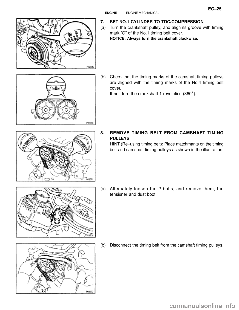
7. SET NO.1 CYLINDER TO TDC/COMPRESSION
(a) Turn the crankshaft pulley, and align its groove with timing
mark ºOº of the No.1 timing belt cover.
NOTICE: Always turn the crankshaft clockwise.
(b) Check that the timing marks of the camshaft timing pulleys
are aligned with the timing marks of the No.4 timing belt
cover.
If not, turn the crankshaft 1 revolution (360°).
8. REMOVE TIMING BELT FROM CAMSHAFT TIMING
PULLEYS
HINT (Re±using timing belt): Place matchmarks on the timing
belt and camshaft timing pulleys as shown in the illustration.
(a) Alternately loosen the 2 bolts, and remove them, the
tensioner and dust boot.
(b) Disconnect the timing belt from the camshaft timing pulleys.
± ENGINEENGINE MECHANICALEG±25
Page 415 of 878
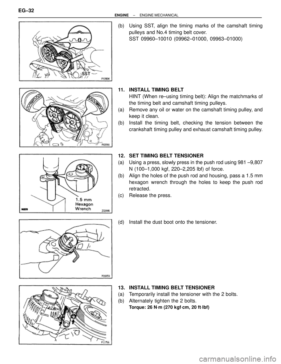
(b) Using SST, align the timing marks of the camshaft timing
pulleys and No.4 timing belt cover.
SST 09960±10010 (09962±01000, 09963±01000)
11. INSTALL TIMING BELT
HINT (When re±using timing belt): Align the matchmarks of
the timing belt and camshaft timing pulleys.
(a) Remove any oil or water on the camshaft timing pulley, and
keep it clean.
(b) Install the timing belt, checking the tension between the
crankshaft timing pulley and exhaust camshaft timing pulley.
12. SET TIMING BELT TENSIONER
(a) Using a press, slowly press in the push rod using 981 ±9,807
N (100±1,000 kgf, 220±2,205 lbf) of force.
(b) Align the holes of the push rod and housing, pass a 1.5 mm
hexagon wrench through the holes to keep the push rod
retracted.
(c) Release the press.
(d) Install the dust boot onto the tensioner.
13. INSTALL TIMING BELT TENSIONER
(a) Temporarily install the tensioner with the 2 bolts.
(b) Alternately tighten the 2 bolts.
Torque: 26 NVm (270 kgfVcm, 20 ftVlbf)
EG±32± ENGINEENGINE MECHANICAL
Page 465 of 878
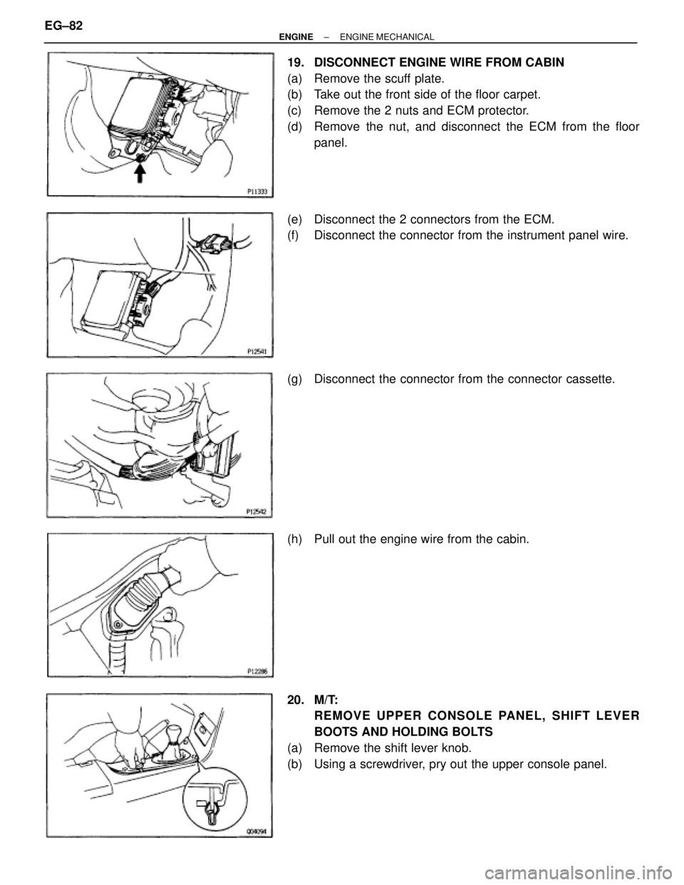
19. DISCONNECT ENGINE WIRE FROM CABIN
(a) Remove the scuff plate.
(b) Take out the front side of the floor carpet.
(c) Remove the 2 nuts and ECM protector.
(d) Remove the nut, and disconnect the ECM from the floor
panel.
(e) Disconnect the 2 connectors from the ECM.
(f) Disconnect the connector from the instrument panel wire.
(g) Disconnect the connector from the connector cassette.
(h) Pull out the engine wire from the cabin.
20. M/T:
REMOVE UPPER CONSOLE PANEL, SHIFT LEVER
BOOTS AND HOLDING BOLTS
(a) Remove the shift lever knob.
(b) Using a screwdriver, pry out the upper console panel. EG±82
± ENGINEENGINE MECHANICAL
Page 466 of 878
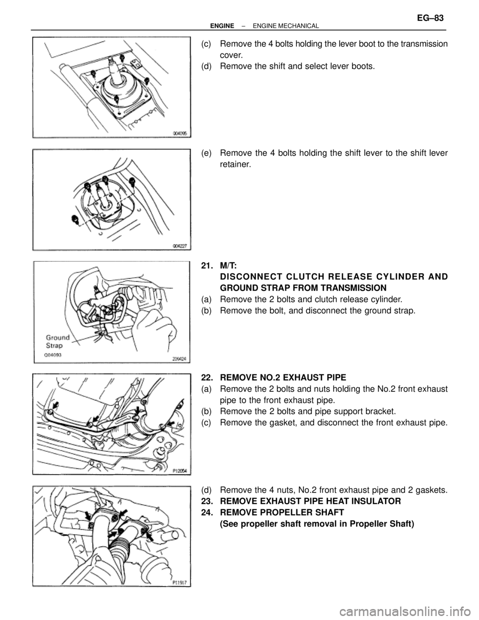
(c) Remove the 4 bolts holding the lever boot to the transmission
cover.
(d) Remove the shift and select lever boots.
(e) Remove the 4 bolts holding the shift lever to the shift lever
retainer.
21. M/T:
DISCONNECT CLUTCH RELEASE CYLINDER AND
GROUND STRAP FROM TRANSMISSION
(a) Remove the 2 bolts and clutch release cylinder.
(b) Remove the bolt, and disconnect the ground strap.
22. REMOVE NO.2 EXHAUST PIPE
(a) Remove the 2 bolts and nuts holding the No.2 front exhaust
pipe to the front exhaust pipe.
(b) Remove the 2 bolts and pipe support bracket.
(c) Remove the gasket, and disconnect the front exhaust pipe.
(d) Remove the 4 nuts, No.2 front exhaust pipe and 2 gaskets.
23. REMOVE EXHAUST PIPE HEAT INSULATOR
24. REMOVE PROPELLER SHAFT
(See propeller shaft removal in Propeller Shaft)
± ENGINEENGINE MECHANICALEG±83
Page 472 of 878
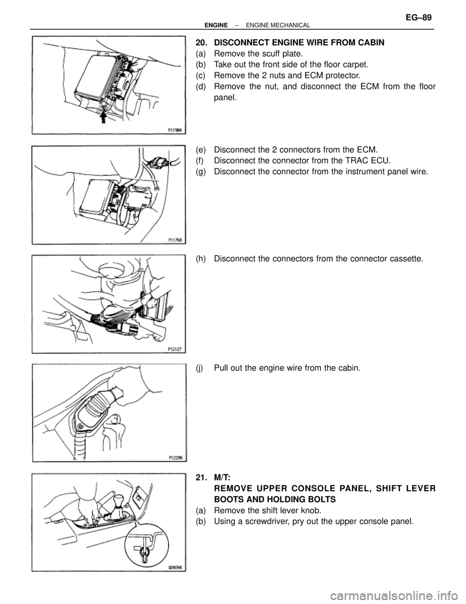
20. DISCONNECT ENGINE WIRE FROM CABIN
(a) Remove the scuff plate.
(b) Take out the front side of the floor carpet.
(c) Remove the 2 nuts and ECM protector.
(d) Remove the nut, and disconnect the ECM from the floor
panel.
(e) Disconnect the 2 connectors from the ECM.
(f) Disconnect the connector from the TRAC ECU.
(g) Disconnect the connector from the instrument panel wire.
(h) Disconnect the connectors from the connector cassette.
(j) Pull out the engine wire from the cabin.
21. M/T:
REMOVE UPPER CONSOLE PANEL, SHIFT LEVER
BOOTS AND HOLDING BOLTS
(a) Remove the shift lever knob.
(b) Using a screwdriver, pry out the upper console panel.
± ENGINEENGINE MECHANICALEG±89
Page 473 of 878
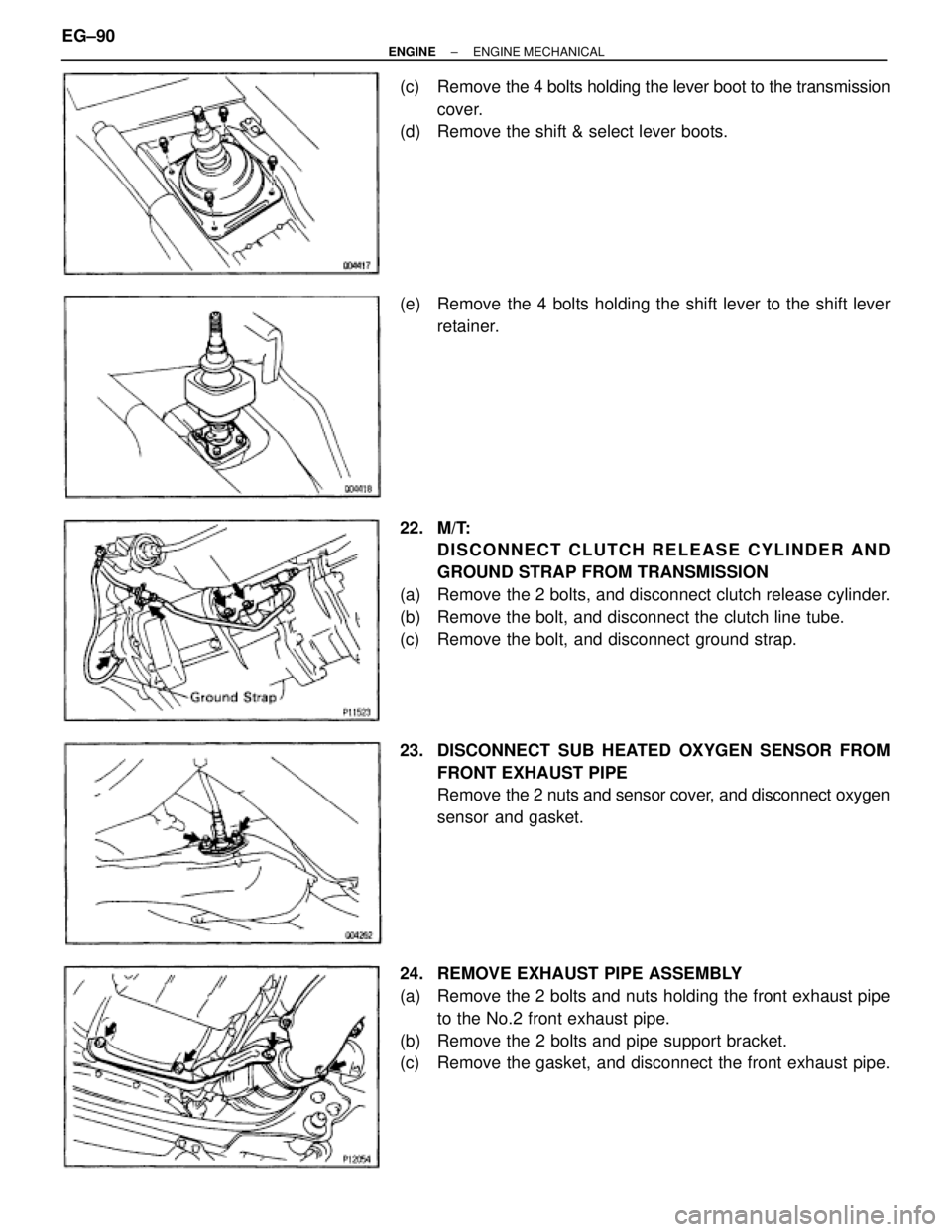
(c) Remove the 4 bolts holding the lever boot to the transmission
cover.
(d) Remove the shift & select lever boots.
(e) Remove the 4 bolts holding the shift lever to the shift lever
retainer.
22. M/T:
DISCONNECT CLUTCH RELEASE CYLINDER AND
GROUND STRAP FROM TRANSMISSION
(a) Remove the 2 bolts, and disconnect clutch release cylinder.
(b) Remove the bolt, and disconnect the clutch line tube.
(c) Remove the bolt, and disconnect ground strap.
23. DISCONNECT SUB HEATED OXYGEN SENSOR FROM
FRONT EXHAUST PIPE
Remove the 2 nuts and sensor cover, and disconnect oxygen
sensor and gasket.
24. REMOVE EXHAUST PIPE ASSEMBLY
(a) Remove the 2 bolts and nuts holding the front exhaust pipe
to the No.2 front exhaust pipe.
(b) Remove the 2 bolts and pipe support bracket.
(c) Remove the gasket, and disconnect the front exhaust pipe. EG±90
± ENGINEENGINE MECHANICAL
Page 510 of 878
5. INSTALL EXHAUST PIPE HEAT INSULATOR
6. INSTALL NO.2 FRONT EXHAUST PIPE
(a) Install 2 new gaskets and the No.2 front exhaust pipe to the
exhaust manifold with 4 new nuts.
Torque: 62 NVm (630 kgfVcm, 46 ftVlbf)
(b) Install the pipe support bracket with the 2 bolts.
Torque: 43 NVm (440 kgfVcm, 32 ftVlbf)
(c) Install a new gasket and the No.2 front exhaust pipe to the
front exhaust pipe with the 2 bolts and 2 new nuts.
Torque: 58 NVm (590 kgfVcm, 43 ftVlbf)
7. M/T:
INSTALL CLUTCH RELEASE CYLINDER AND GROUND
STRAP
(a) Install the clutch release cylinder with the 2 bolts.
Torque: 13 NVm (130 kgfVcm, 9 ftVlbf)
(b) Install the ground strap with the bolt.
Torque: 37 NVm (380 kgfVcm, 27 ftVlbf)
8. M/T:
INSTALL UPPER CONSOLE PANEL, SHIFT LEVER
BOOTS AND HOLDING BOLTS
9. CONNECT ENGINE WIRE TO CABIN
(a) Push in the engine wire through the cowl panel.
NOTICE: Be careful not to damage the engine wire.
(b) Connect the connector to the connector cassette.
(c) Connect the connector to the instrament panel wire
connector.
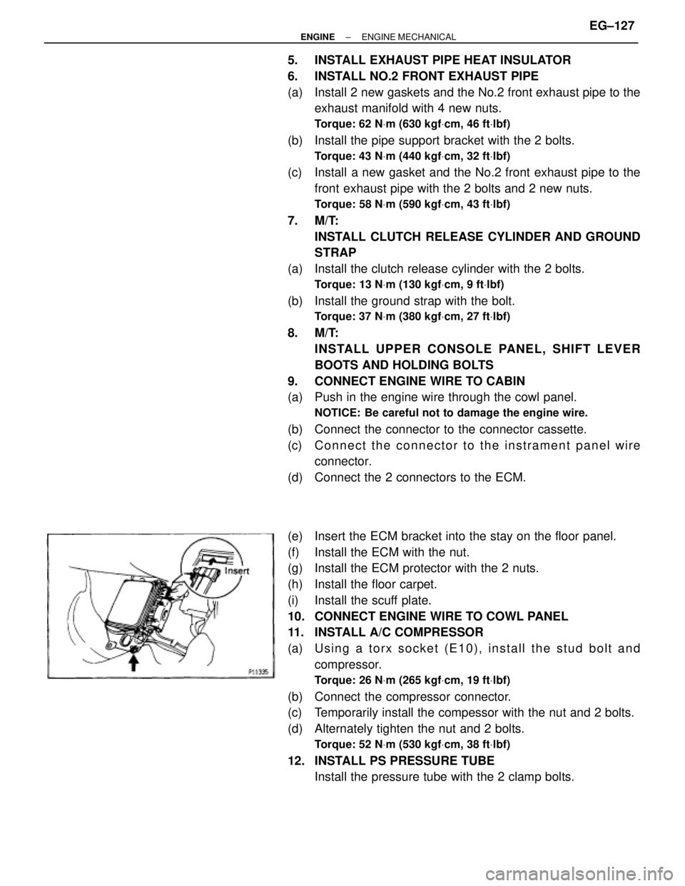
(d) Connect the 2 connectors to the ECM.
(e) Insert the ECM bracket into the stay on the floor panel.
(f) Install the ECM with the nut.
(g) Install the ECM protector with the 2 nuts.
(h) Install the floor carpet.
(i) Install the scuff plate.
10. CONNECT ENGINE WIRE TO COWL PANEL
11. INSTALL A/C COMPRESSOR
(a) U s i n g a t o r x s o c k e t ( E 1 0 ) , i n s t a l l t h e s t u d b o l t a n d
compressor.
Torque: 26 NVm (265 kgfVcm, 19 ftVlbf)
(b) Connect the compressor connector.
(c) Temporarily install the compessor with the nut and 2 bolts.
(d) Alternately tighten the nut and 2 bolts.
Torque: 52 NVm (530 kgfVcm, 38 ftVlbf)
12. INSTALL PS PRESSURE TUBE
Install the pressure tube with the 2 clamp bolts.
± ENGINEENGINE MECHANICALEG±127
Page 513 of 878
5. INSTALL REAR CENTER FLOOR CROSSMEMBER
BRACE
Torque: 28 NVm (290 kgfVcm, 21 ftVlbf)
6. INSTALL EXHAUST PIPE HEAT INSULATOR
7. INSTALL NO.2 FRONT EXHAUST PIPE
Install a new gasket and the front exhaust pipe with 3 new
nuts.
Torque: 62 NVm (630 kgfVcm, 46 ftVlbf)
8. INSTALL EXHAUST PIPE ASSEMBLY
(a) Install the hook of the tailpipe to the 2 rings on the tailpipe
bracket.
(b) Install the hook of the exhaust pipe to the 2 rings on the
exhaust pipe brackets.
(c) Install the pipe support bracket with the 2 bolts.
Torque: 43 NVm (440 kgfVcm, 32 ftVlbf)
(d) Install a new gasket and the No.2 front exhaust pipe to the
front exhaust pipe with the 2 bolts and 2 new nuts.
Torque: 58 NVm (590 kgfVcm, 43 ftVlbf)
9. INSTALL SUB HEATED OXYGEN SENSOR
Install a new gasket, the oxygen sensor and sensor cover
with the 2 nuts.
Torque: 18 NVm (180 kgfVcm, 13 ftVlbf)
10. M/T:
INSTALL CLUTCH RELEASE CYLINDER AND GROUND
STRAP
(a) Install the clutch release cylinder with the 2 bolts.
Torque: 13 NVm (130 kgfVcm, 9 ftVlbf)
(b) Connect the clutch line tube with the bolt.
Torque: 37 NVm (380 kgfVcm, 27 ftVlbf)
(c) Install the ground strap with the bolt.
Torque: 37 NVm (380 kgfVcm, 27 ftVlbf)
11. CONNECT ENGINE WIRE TO CABIN
(a) Push in the engine wire through the cowl panel.
NOTICE: Be careful not to damage the engine wire.
(b) Connect the 2 connectors to the connector cassette.
(c) Connect the connector to the instrument panel wire
connector.
(d) Connect the 2 connectors to the ECM.
(e) Connect the connector to the TRAC ECU.
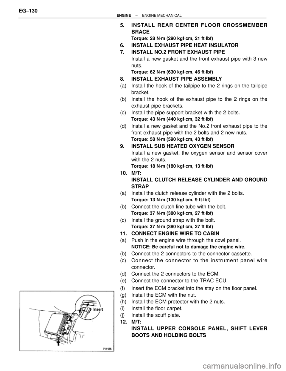
(f) Insert the ECM bracket into the stay on the floor panel.
(g) Install the ECM with the nut.
(h) Install the ECM protector with the 2 nuts.
(i) Install the floor carpet.
(j) Install the scuff plate.
12. M/T:
INSTALL UPPER CONSOLE PANEL, SHIFT LEVER
BOOTS AND HOLDING BOLTS EG±130
± ENGINEENGINE MECHANICAL