Page 584 of 878
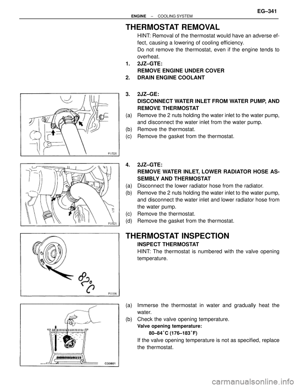
THERMOSTAT REMOVAL
HINT: Removal of the thermostat would have an adverse ef-
fect, causing a lowering of cooling efficiency.
Do not remove the thermostat, even if the engine tends to
overheat.
1. 2JZ±GTE:
REMOVE ENGINE UNDER COVER
2. DRAIN ENGINE COOLANT
3. 2JZ±GE:
DISCONNECT WATER INLET FROM WATER PUMP, AND
REMOVE THERMOSTAT
(a) Remove the 2 nuts holding the water inlet to the water pump,
and disconnect the water inlet from the water pump.
(b) Remove the thermostat.
(c) Remove the gasket from the thermostat.
4. 2JZ±GTE:
REMOVE WATER INLET, LOWER RADIATOR HOSE AS-
SEMBLY AND THERMOSTAT
(a) Disconnect the lower radiator hose from the radiator.
(b) Remove the 2 nuts holding the water inlet to the water pump,
and disconnect the water inlet and lower radiator hose from
the water pump.
(c) Remove the thermostat.
(d) Remove the gasket from the thermostat.
THERMOSTAT INSPECTION
INSPECT THERMOSTAT
HINT: The thermostat is numbered with the valve opening
temperature.
(a) Immerse the thermostat in water and gradually heat the
water.
(b) Check the valve opening temperature.
Valve opening temperature:
80±84°C (176±183°F)
If the valve opening temperature is not as specified, replace
the thermostat.
± ENGINECOOLING SYSTEMEG±341
Page 585 of 878
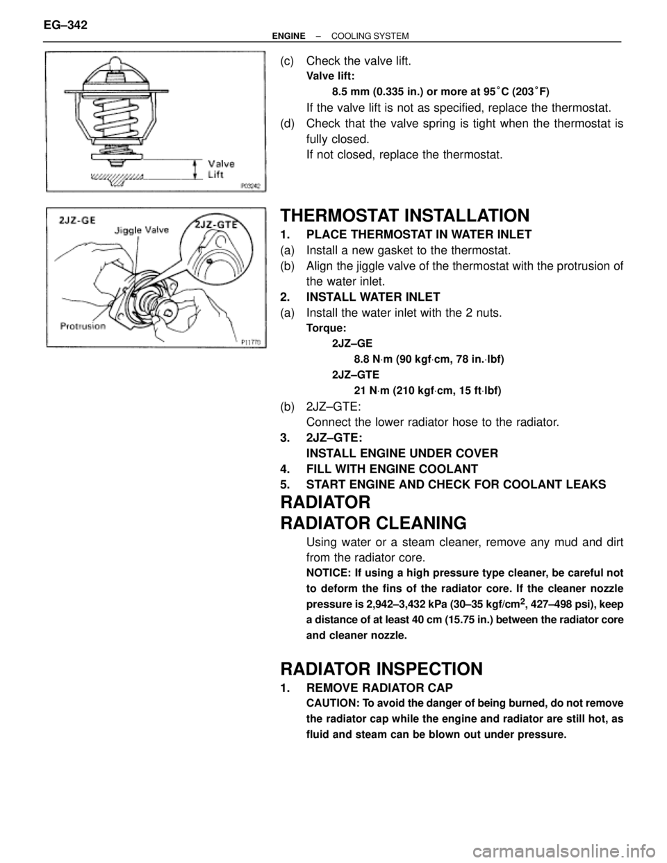
(c) Check the valve lift.
Valve lift:
8.5 mm (0.335 in.) or more at 95°C (203°F)
If the valve lift is not as specified, replace the thermostat.
(d) Check that the valve spring is tight when the thermostat is
fully closed.
If not closed, replace the thermostat.
THERMOSTAT INSTALLATION
1. PLACE THERMOSTAT IN WATER INLET
(a) Install a new gasket to the thermostat.
(b) Align the jiggle valve of the thermostat with the protrusion of
the water inlet.
2. INSTALL WATER INLET
(a) Install the water inlet with the 2 nuts.
Torque:
2JZ±GE
8.8 NVm (90 kgfVcm, 78 in.Vlbf)
2JZ±GTE
21 NVm (210 kgfVcm, 15 ftVlbf)
(b) 2JZ±GTE:
Connect the lower radiator hose to the radiator.
3. 2JZ±GTE:
INSTALL ENGINE UNDER COVER
4. FILL WITH ENGINE COOLANT
5. START ENGINE AND CHECK FOR COOLANT LEAKS
RADIATOR
RADIATOR CLEANING
Using water or a steam cleaner, remove any mud and dirt
from the radiator core.
NOTICE: If using a high pressure type cleaner, be careful not
to deform the fins of the radiator core. If the cleaner nozzle
pressure is 2,942±3,432 kPa (30±35 kgf/cm
2, 427±498 psi), keep
a distance of at least 40 cm (15.75 in.) between the radiator core
and cleaner nozzle.
RADIATOR INSPECTION
1. REMOVE RADIATOR CAP
CAUTION: To avoid the danger of being burned, do not remove
the radiator cap while the engine and radiator are still hot, as
fluid and steam can be blown out under pressure.
EG±342± ENGINECOOLING SYSTEM
Page 586 of 878
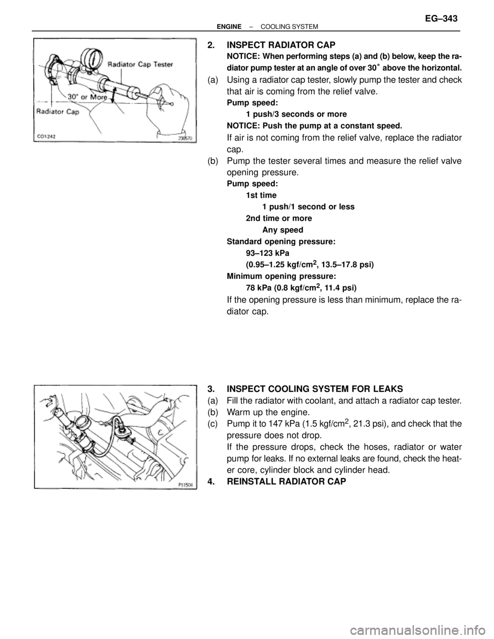
2. INSPECT RADIATOR CAP
NOTICE: When performing steps (a) and (b) below, keep the ra-
diator pump tester at an angle of over 30° above the horizontal.
(a) Using a radiator cap tester, slowly pump the tester and check
that air is coming from the relief valve.
Pump speed:
1 push/3 seconds or more
NOTICE: Push the pump at a constant speed.
If air is not coming from the relief valve, replace the radiator
cap.
(b) Pump the tester several times and measure the relief valve
opening pressure.
Pump speed:
1st time
1 push/1 second or less
2nd time or more
Any speed
Standard opening pressure:
93±123 kPa
(0.95±1.25 kgf/cm
2, 13.5±17.8 psi)
Minimum opening pressure:
78 kPa (0.8 kgf/cm
2, 11.4 psi)
If the opening pressure is less than minimum, replace the ra-
diator cap.
3. INSPECT COOLING SYSTEM FOR LEAKS
(a) Fill the radiator with coolant, and attach a radiator cap tester.
(b) Warm up the engine.
(c) Pump it to 147 kPa (1.5 kgf/cm
2, 21.3 psi), and check that the
pressure does not drop.
If the pressure drops, check the hoses, radiator or water
pump for leaks. If no external leaks are found, check the heat-
er core, cylinder block and cylinder head.
4. REINSTALL RADIATOR CAP
± ENGINECOOLING SYSTEMEG±343
Page 589 of 878
RADIATOR REMOVAL
Installation is in the reverse order of removal.
1. REMOVE ENGINE UNDER COVER
INSTALLATION HINT: Start the engine, and check for cool-
ant and A/T fluid leaks.
2. REMOVE BATTERY AND BATTERY TRAY
3. DRAIN ENGINE COOLANT
4. 2JZ±GTE:
REMOVE NO.2 AIR TUBE
5. REMOVE NO.2 FAN SHROUD
(a) Remove the 2 clips.
(b) Disconnect the claw of the No.2 fan shroud from the hook of
the No.1 fan shroud, and remove the No.2 fan shroud.
6. REMOVE AIR CLEANER DUCT
7. 2JZ±GTE:
REMOVE NO.5 AIR HOSE
8. REMOVE LH HEADLIGHT BEAM ANGLE GAUGE
Remove the screw and beam angle gauge.
9. DISCONNECT HOSES FROM RADIATOR
Disconnect these hoses from the radiator:
(1) Reservoir inlet hose
(2) Upper radiator hose
(3) Lower radiator hose
(4) A/T:
2 oil cooler hoses
Plug the hose ends.
INSTALLATION HINT: Check the A/T fluid level.
(See item 21 in Maintenance) EG±346
± ENGINECOOLING SYSTEM
Page 590 of 878
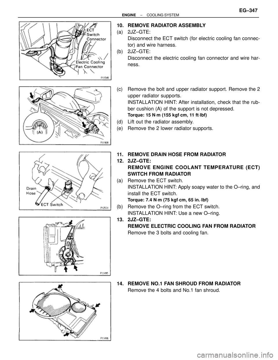
10. REMOVE RADIATOR ASSEMBLY
(a) 2JZ±GTE:
Disconnect the ECT switch (for electric cooling fan connec-
tor) and wire harness.
(b) 2JZ±GTE:
Disconnect the electric cooling fan connector and wire har-
ness.
(c) Remove the bolt and upper radiator support. Remove the 2
upper radiator supports.
INSTALLATION HINT: After installation, check that the rub-
ber cushion (A) of the support is not depressed.
Torque: 15 NVm (155 kgfVcm, 11 ftVlbf)
(d) Lift out the radiator assembly.
(e) Remove the 2 lower radiator supports.
11. REMOVE DRAIN HOSE FROM RADIATOR
12. 2JZ±GTE:
REMOVE ENGINE COOLANT TEMPERATURE (ECT)
SWITCH FROM RADIATOR
(a) Remove the ECT switch.
INSTALLATION HINT: Apply soapy water to the O±ring, and
install the ECT switch.
Torque: 7.4 NVm (75 kgfVcm, 65 in.Vlbf)
(b) Remove the O±ring from the ECT switch.
INSTALLATION HINT: Use a new O±ring.
13. 2JZ±GTE:
REMOVE ELECTRIC COOLING FAN FROM RADIATOR
Remove the 3 bolts and cooling fan.
14. REMOVE NO.1 FAN SHROUD FROM RADIATOR
Remove the 4 bolts and No.1 fan shroud.
± ENGINECOOLING SYSTEMEG±347
Page 596 of 878
ELECTRIC COOLING FAN (2JZ±GTE)
On±Vehicle Inspection
1. C H E C K C O O L I N G FA N O P E R AT I O N W I T H L O W
TEMPERATURE (Below 88°C (190°F))
(a) Turn the ignition switch ON.
(b) Check that the cooling fan stops.
If not, check the cooling fan relay and ECT switch, and check
for a separated connector or severed wire between the No.1
radiator fan relay and ECT switch.
(c) Disconnect the ECT switch connector.
(d) Check that the cooling fan rotates.
If not, check the No.1 radiator relay, No.2 radiator fan relay,
cooling fan, fuses, and check for short circuit between the
No.1 radiator fan relay and ECT switch.
(e) Reconnect the ECT switch connector.
2. CHECK COOLING FAN OPERATION WITH HIGH
TEMPERATURE (Above 97°C (207°F))
(a) Start the engine, and raise coolant temperature to above
97°C (207°F).
(b) Check that the cooling fan rotates.
If not, replace the ECT switch.
± ENGINECOOLING SYSTEMEG±353
Page 599 of 878
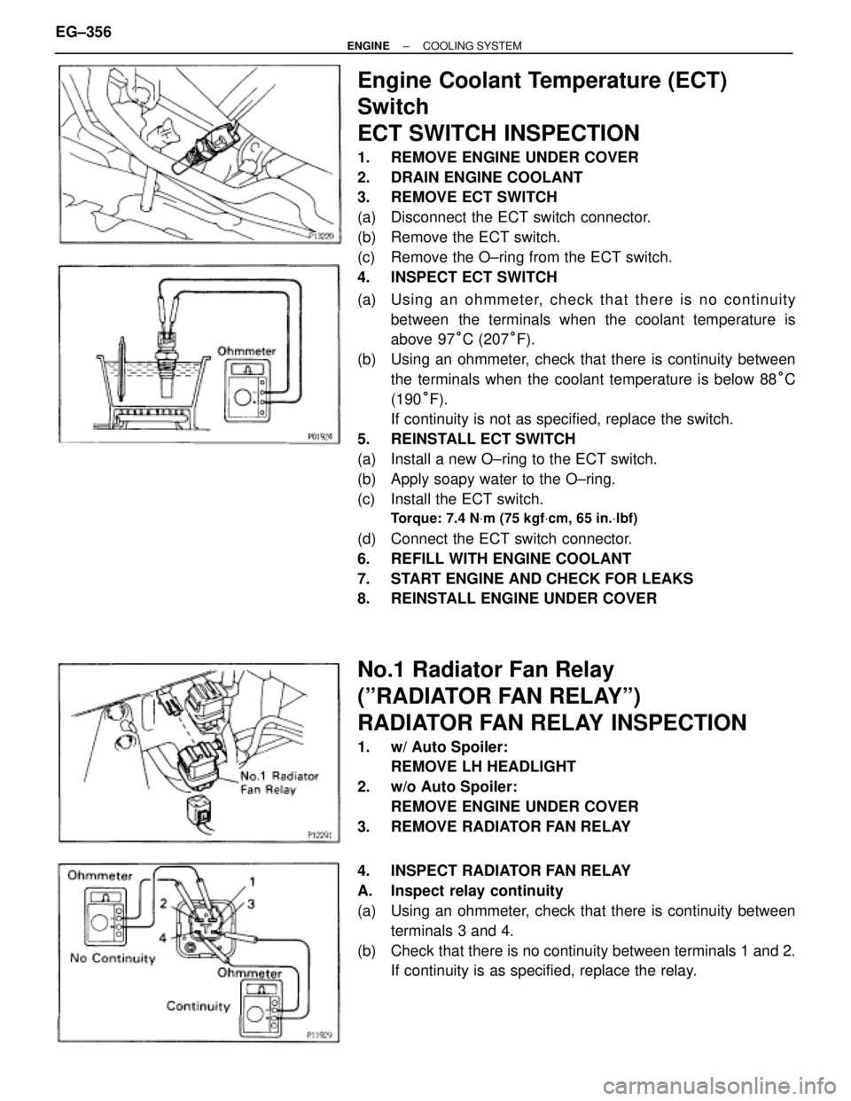
Engine Coolant Temperature (ECT)
Switch
ECT SWITCH INSPECTION
1. REMOVE ENGINE UNDER COVER
2. DRAIN ENGINE COOLANT
3. REMOVE ECT SWITCH
(a) Disconnect the ECT switch connector.
(b) Remove the ECT switch.
(c) Remove the O±ring from the ECT switch.
4. INSPECT ECT SWITCH
(a) Usin g an oh mme te r, ch e ck th a t th e re is no co n tin u ity
between the terminals when the coolant temperature is
above 97°C (207°F).
(b) Using an ohmmeter, check that there is continuity between
the terminals when the coolant temperature is below 88°C
(190°F).
If continuity is not as specified, replace the switch.
5. REINSTALL ECT SWITCH
(a) Install a new O±ring to the ECT switch.
(b) Apply soapy water to the O±ring.
(c) Install the ECT switch.
Torque: 7.4 NVm (75 kgfVcm, 65 in.Vlbf)
(d) Connect the ECT switch connector.
6. REFILL WITH ENGINE COOLANT
7. START ENGINE AND CHECK FOR LEAKS
8. REINSTALL ENGINE UNDER COVER
No.1 Radiator Fan Relay
(ºRADIATOR FAN RELAYº)
RADIATOR FAN RELAY INSPECTION
1. w/ Auto Spoiler:
REMOVE LH HEADLIGHT
2. w/o Auto Spoiler:
REMOVE ENGINE UNDER COVER
3. REMOVE RADIATOR FAN RELAY
4. INSPECT RADIATOR FAN RELAY
A. Inspect relay continuity
(a) Using an ohmmeter, check that there is continuity between
terminals 3 and 4.
(b) Check that there is no continuity between terminals 1 and 2.
If continuity is as specified, replace the relay. EG±356
± ENGINECOOLING SYSTEM
Page 626 of 878
![TOYOTA SUPRA 1986 Service Repair Manual 24
ELECTRICAL WIRING ROUTING
Position of Parts in Engine Compartment
[2JZ±GTE]
A 1 A/C Ambient Temp. Sensor E 4 Engine Coolant Temp. Sender (Water Temp. Sender)
A 2 A/C Condenser Fan Motor E 5 Engine TOYOTA SUPRA 1986 Service Repair Manual 24
ELECTRICAL WIRING ROUTING
Position of Parts in Engine Compartment
[2JZ±GTE]
A 1 A/C Ambient Temp. Sensor E 4 Engine Coolant Temp. Sender (Water Temp. Sender)
A 2 A/C Condenser Fan Motor E 5 Engine](/manual-img/14/57467/w960_57467-625.png)
24
ELECTRICAL WIRING ROUTING
Position of Parts in Engine Compartment
[2JZ±GTE]
A 1 A/C Ambient Temp. Sensor E 4 Engine Coolant Temp. Sender (Water Temp. Sender)
A 2 A/C Condenser Fan Motor E 5 Engine Coolant Temp. SW (Water Temp. SW)
A 3 A/C Triple Pressure SW E 6 Engine Hood Courtesy SW
(A/C Dual and Single Pressure SW) E 7 Engine Oil Level Sensor
A 4 A/C Magnetic Clutch and Lock Sensor
A 5 A/T Fluid Temp. Sensor F 1 Front Airbag Sensor LH
A 6 ABS Actuator F 2 Front Airbag Sensor RH
A 7 ABS Actuator F 3 Front Fog Light and Parking Light LH
A 10 ABS Speed Sensor Front LH F 4 Front Fog Light and Parking Light RH
A 11 ABS Speed Sensor Front RH F 5 Front Side Marker Light LH
F 6 Front Side Marker Light RH
B 1 Back±Up Light SW (for M/T) F 7 Front Turn Signal Light LH
B 2 Brake Fluid Level Warning SW F 8 Front Turn Signal Light RH
F 9 Front Wiper Motor
C 1 Camshaft Position Sensor No. 1
C 2 Camshaft Position Sensor No. 2 G 1 Generator (Alternator)
C 3 Crankshaft Position Sensor G 2 Generator (Alternator)
C 4 Cruise Control Actuator
H 1 Headlight Hi LH
D 1 Data Link Connector 1 (Check Connector) H 2 Headlight Hi RH
D 2 Daytime Running Light Relay No. 3 H 3 Headlight Lo LH
D 3 Daytime Running Light Relay No. 3 H 4 Headlight Lo RH
H 5 Heated Oxygen Sensor (Main)
E 1 EGR Gas Temp. Sensor H 8 Horn LH
E 2 Electronically Controlled Transmission Solenoid H 9 Horn RH
E 3 Engine Coolant Temp. Sensor (EFI Water Temp. Sensor)