Page 275 of 878

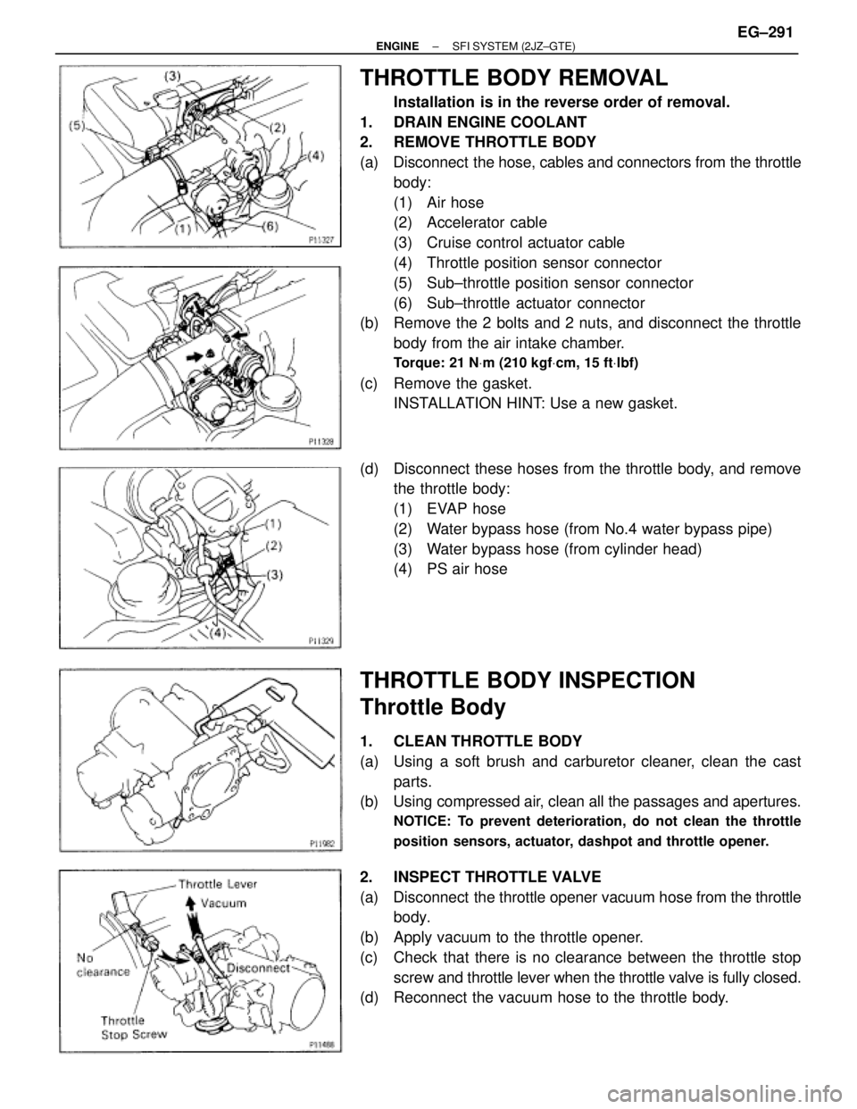
THROTTLE BODY REMOVAL
Installation is in the reverse order of removal.
1. DRAIN ENGINE COOLANT
2. REMOVE THROTTLE BODY
(a) Disconnect the hose, cables and connectors from the throttle
body:
(1) Air hose
(2) Accelerator cable
(3) Cruise control actuator cable
(4) Throttle position sensor connector
(5) Sub±throttle position sensor connector
(6) Sub±throttle actuator connector
(b) Remove the 2 bolts and 2 nuts, and disconnect the throttle
body from the air intake chamber.
Torque: 21 NVm (210 kgfVcm, 15 ftVlbf)
(c) Remove the gasket.
INSTALLATION HINT: Use a new gasket.
(d) Disconnect these hoses from the throttle body, and remove
the throttle body:
(1) EVAP hose
(2) Water bypass hose (from No.4 water bypass pipe)
(3) Water bypass hose (from cylinder head)
(4) PS air hose
THROTTLE BODY INSPECTION
Throttle Body
1. CLEAN THROTTLE BODY
(a) Using a soft brush and carburetor cleaner, clean the cast
parts.
(b) Using compressed air, clean all the passages and apertures.
NOTICE: To prevent deterioration, do not clean the throttle
position sensors, actuator, dashpot and throttle opener.
2. INSPECT THROTTLE VALVE
(a) Disconnect the throttle opener vacuum hose from the throttle
body.
(b) Apply vacuum to the throttle opener.
(c) Check that there is no clearance between the throttle stop
screw and throttle lever when the throttle valve is fully closed.
(d) Reconnect the vacuum hose to the throttle body.
± ENGINESFI SYSTEM (2JZ±GTE)EG±291
Page 281 of 878
IAC VALVE REMOVAL
1. DRAIN ENGINE COOLANT
2. DISCONNECT IAC VAVE CONNECTOR
3. REMOVE IAC VALVE
(a) Remove the 2 bolts, and disconnect the IAC valve from the
air intake chamber.
(b) Remove the gasket.
(c) Disconnect these hoses from the IAC valve, and remove the
IAC valve:
(1) Air hose
(2) Water bypass hose (from No.2 water bypass pipe)
(3) Water bypass hose (from No.4 water bypass pipe)
(d) Remove the seal washer and check valve.
IAC VALVE INSPECTION
INSPECT IAC VALVE OPERATION
(a) Apply battery voltage to terminals B1 and B2, and while
repeatedly grounding S1±S2±S3±S4±S 1 in sequence, and
check that the valve moves toward the closed position.
(b) Apply battery voltage to terminals B1 and B2, and while
repeatedly grounding S4±S3±S2±S1±S 4 in sequence,
check that the valve moves toward the open position.
If operation is not as specified, replace the IAC valve.
± ENGINESFI SYSTEM (2JZ±GTE)EG±297
Page 282 of 878

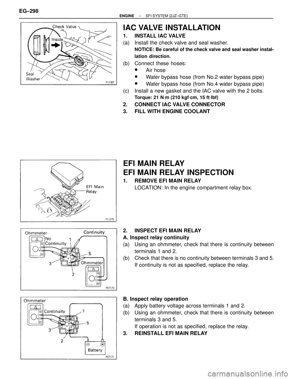
IAC VALVE INSTALLATION
1. INSTALL IAC VALVE
(a) Install the check valve and seal washer.
NOTICE: Be careful of the check valve and seal washer instal-
lation direction.
(b) Connect these hoses:
wAir hose
wWater bypass hose (from No.2 water bypass pipe)
wWater bypass hose (from No.4 water bypass pipe)
(c) Install a new gasket and the IAC valve with the 2 bolts.
Torque: 21 NVm (210 kgfVcm, 15 ftVlbf)
2. CONNECT IAC VALVE CONNECTOR
3. FILL WITH ENGINE COOLANT
EFI MAIN RELAY
EFI MAIN RELAY INSPECTION
1. REMOVE EFI MAIN RELAY
LOCATION: In the engine compartment relay box.
2. INSPECT EFI MAIN RELAY
A. Inspect relay continuity
(a) Using an ohmmeter, check that there is continuity between
terminals 1 and 2.
(b) Check that there is no continuity between terminals 3 and 5.
If continuity is not as specified, replace the relay.
B. Inspect relay operation
(a) Apply battery voltage across terminals 1 and 2.
(b) Using an ohmmeter, check that there is continuity between
terminals 3 and 5.
If operation is not as specified, replace the relay.
3. REINSTALL EFI MAIN RELAY EG±298
± ENGINESFI SYSTEM (2JZ±GTE)
Page 295 of 878
C. Inspect VSV operation
(a) Check that air does not flow from port E to F.
(b) Apply battery voltage across the terminals.
(c) Check that air flows from port E to F.
If operation is not as specified, replace the VSV.
3. REINSTALL VSV
ENGINE COOLANT TEMPERATURE
(ECT) SENSOR
COMPONENTS FOR REMOVAL AND
INSTALLATION
± ENGINESFI SYSTEM (2JZ±GTE)EG±311
Page 296 of 878
ECT SENSOR INSPECTION
1. DRAIN ENGINE COOLANT
2. REMOVE ECT SENSOR
(a) Disconnect the ECT sensor connector.
(b) Using SST, remove the ECT sensor and gasket.
SST 09205±76030
3. INSPECT ECT SENSOR
Using an ohmmeter, measure the resistance between the ter-
minals.
Resistance:
Refer to the graph
If the resistance is not as specified, replace the ECT sensor.
4. REINSTALL ECT SENSOR
(a) Install a new gasket to the ECT sensor.
(b) Using SST, install the ECT sensor.
SST 09205±76030
(c) Connect the ECT sensor connector.
5. REFILL WITH ENGINE COOLANT EG±312
± ENGINESFI SYSTEM (2JZ±GTE)
Page 314 of 878

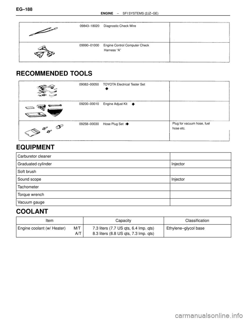
09843±18020 Diagnostic Check Wire
09990±01000Engine Control Computer Check
Harness ªAº
RECOMMENDED TOOLS
09082±00050 TOYOTA Electrical Tester Set
09200±00010Engine Adjust Kit
09258±00030 Hose Plug SetPlug for vacuum hose, fuel
hose etc.
EQUIPMENT
�������������������������� ��������������������������Carburetor cleaner����������� �����������
�������������������������� �
������������������������� ��������������������������Graduated cylinder����������� �
���������� �����������Injector
�������������������������� ��������������������������Soft brush����������� �����������
�������������������������� ��������������������������Sound scope����������� �����������Injector
�������������������������� ��������������������������Tachometer����������� �����������
�������������������������� ��������������������������Torque wrench����������� �����������
�������������������������� �
������������������������� ��������������������������Vacuum gauge
����������� �
���������� �����������
COOLANT������������ �
����������� ������������Item
�������������� �
������������� ��������������Capacity
������������ �
����������� ������������Classification
������������ �
����������� ������������
Engine coolant (w/ Heater) M/T
A/T�������������� �
������������� ��������������
7.3 liters (7.7 US qts, 6.4 lmp. qts)
8.3 liters (8.8 US qts, 7.3 lmp. qts)������������ �
����������� ������������
Ethylene±glycol base
EG±188± ENGINESFI SYSTEMS (2JZ±GE)
Page 330 of 878

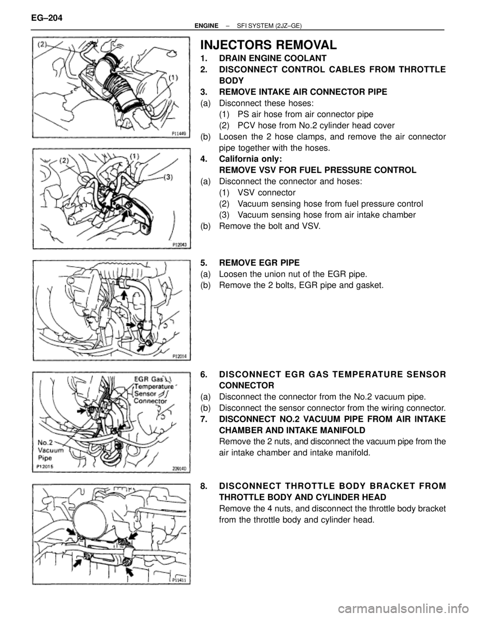
INJECTORS REMOVAL
1. DRAIN ENGINE COOLANT
2. DISCONNECT CONTROL CABLES FROM THROTTLE
BODY
3. REMOVE INTAKE AIR CONNECTOR PIPE
(a) Disconnect these hoses:
(1) PS air hose from air connector pipe
(2) PCV hose from No.2 cylinder head cover
(b) Loosen the 2 hose clamps, and remove the air connector
pipe together with the hoses.
4. California only:
REMOVE VSV FOR FUEL PRESSURE CONTROL
(a) Disconnect the connector and hoses:
(1) VSV connector
(2) Vacuum sensing hose from fuel pressure control
(3) Vacuum sensing hose from air intake chamber
(b) Remove the bolt and VSV.
5. REMOVE EGR PIPE
(a) Loosen the union nut of the EGR pipe.
(b) Remove the 2 bolts, EGR pipe and gasket.
6. DISCONNECT EGR GAS TEMPERATURE SENSOR
CONNECTOR
(a) Disconnect the connector from the No.2 vacuum pipe.
(b) Disconnect the sensor connector from the wiring connector.
7. DISCONNECT NO.2 VACUUM PIPE FROM AIR INTAKE
CHAMBER AND INTAKE MANIFOLD
Remove the 2 nuts, and disconnect the vacuum pipe from the
air intake chamber and intake manifold.
8. DISCONNECT THROTTLE BODY BRACKET FROM
THROTTLE BODY AND CYLINDER HEAD
Remove the 4 nuts, and disconnect the throttle body bracket
from the throttle body and cylinder head. EG±204
± ENGINESFI SYSTEM (2JZ±GE)
Page 339 of 878
Torque: 64 NVm (650 kgfVcm, 47 ftVlbf)
13. California only:
INSTALL VSV FOR FUEL PRESSURE CONTROL
14. INSTALL INTAKE AIR CONNECTOR PIPE
15. CONNECT CONTROL CABLES TO THROTTLE BODY
16. FILL WITH ENGINE COOLANT
17. CHECK FOR FUEL LEAKS
(See item 5 in fuel system in precaution)
FUEL PRESSURE PULSATION DAMPER
COMPONENTS FOR REMOVAL AND
INSTALLATION
FUEL PRESSURE PULSATION DAMPER
REMOVAL
1. REMOVE STARTER
(See starter removal in Starting System)
2. REMOVE FUEL PRESSURE PULSATION DAMPER
(a) Remove the pulsation damper and upper gasket.
(b) Disconnect the fuel inlet pipe from the fuel pipe support, and
remove the lower gasket.
± ENGINESFI SYSTEM (2JZ±GE)EG±213