Page 348 of 878
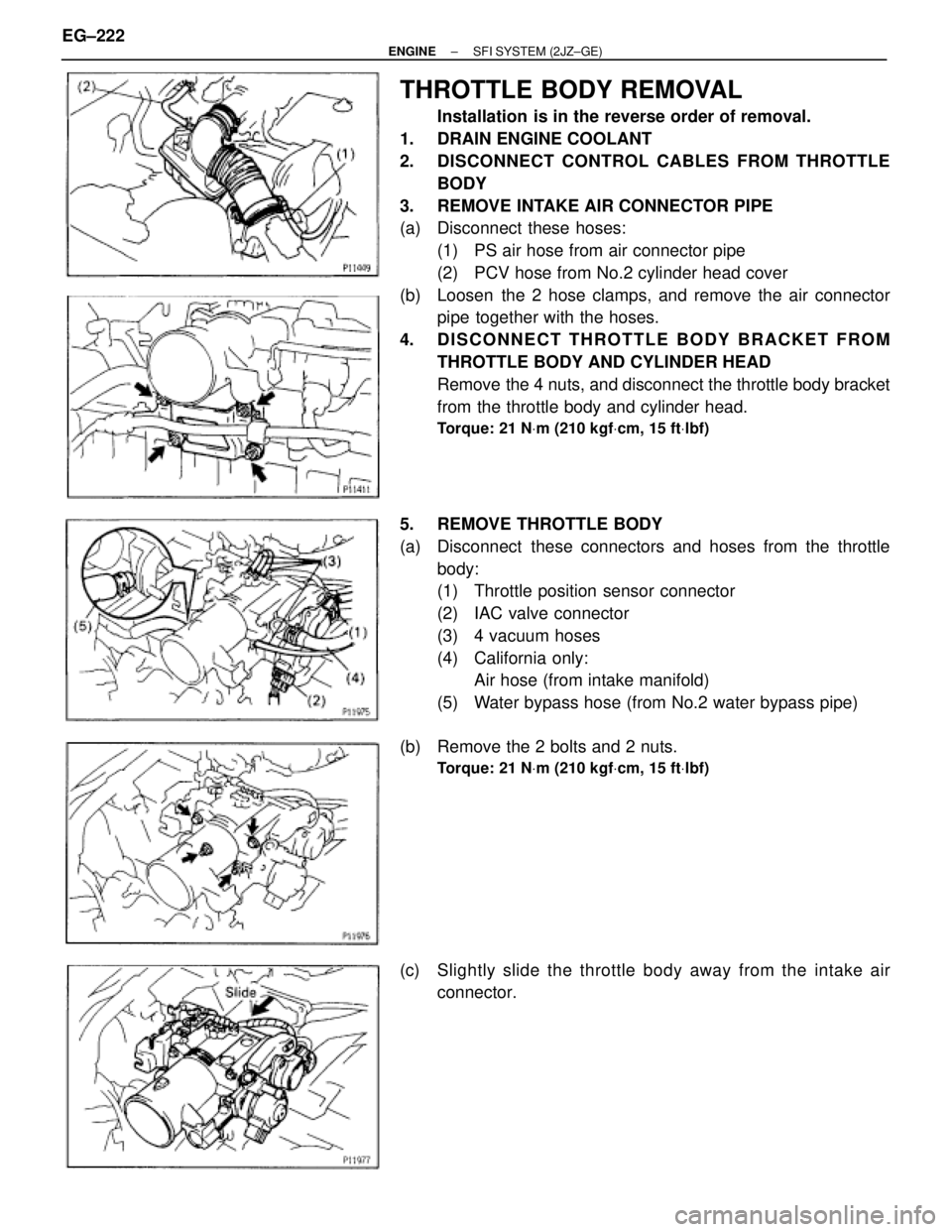
THROTTLE BODY REMOVAL
Installation is in the reverse order of removal.
1. DRAIN ENGINE COOLANT
2. DISCONNECT CONTROL CABLES FROM THROTTLE
BODY
3. REMOVE INTAKE AIR CONNECTOR PIPE
(a) Disconnect these hoses:
(1) PS air hose from air connector pipe
(2) PCV hose from No.2 cylinder head cover
(b) Loosen the 2 hose clamps, and remove the air connector
pipe together with the hoses.
4. DISCONNECT THROTTLE BODY BRACKET FROM
THROTTLE BODY AND CYLINDER HEAD
Remove the 4 nuts, and disconnect the throttle body bracket
from the throttle body and cylinder head.
Torque: 21 NVm (210 kgfVcm, 15 ftVlbf)
5. REMOVE THROTTLE BODY
(a) Disconnect these connectors and hoses from the throttle
body:
(1) Throttle position sensor connector
(2) IAC valve connector
(3) 4 vacuum hoses
(4) California only:
Air hose (from intake manifold)
(5) Water bypass hose (from No.2 water bypass pipe)
(b) Remove the 2 bolts and 2 nuts.
Torque: 21 NVm (210 kgfVcm, 15 ftVlbf)
(c) Slightly slide the throttle body away from the intake air
connector. EG±222
± ENGINESFI SYSTEM (2JZ±GE)
Page 368 of 878
ENGINE COOLANT TEMPERATURE
(ECT) SENSOR
COMPONENTS FOR REMOVAL AND
INSTALLATION
ECT SENSOR INSPECTION
1. DRAIN ENGINE COOLANT
2. REMOVE ECT SENSOR
(a) Disconnect the ECT sensor connector.
(b) Using SST, remove the ECT sensor and gasket.
SST 09205±76030 EG±242
± ENGINESFI SYSTEM (2JZ±GE)
Page 369 of 878
3. INSPECT ECT SENSOR
Using an ohmmeter, measure the resistance between the ter-
minals.
Resistance:
Refer to the graph
If the resistance is not as specified, replace the ECT sensor.
4. REINSTALL ECT SENSOR
(a) Install a new gasket to the ECT sensor.
(b) Using SST, install the ECT sensor.
SST 09205±76030
(c) Connect the ECT sensor connector.
5. REFILL WITH ENGINE COOLANT
± ENGINESFI SYSTEM (2JZ±GE)EG±243
Page 424 of 878
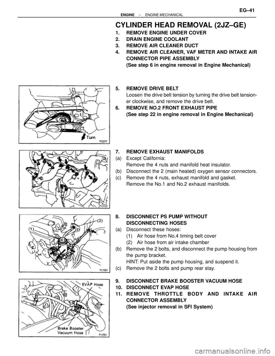
CYLINDER HEAD REMOVAL (2JZ±GE)
1. REMOVE ENGINE UNDER COVER
2. DRAIN ENGINE COOLANT
3. REMOVE AIR CLEANER DUCT
4. REMOVE AIR CLEANER, VAF METER AND INTAKE AIR
CONNECTOR PIPE ASSEMBLY
(See step 6 in engine removal in Engine Mechanical)
5. REMOVE DRIVE BELT
Loosen the drive belt tension by turning the drive belt tension-
er clockwise, and remove the drive belt.
6. REMOVE NO.2 FRONT EXHAUST PIPE
(See step 22 in engine removal in Engine Mechanical)
7. REMOVE EXHAUST MANIFOLDS
(a) Except California:
Remove the 4 nuts and manifold heat insulator.
(b) Disconnect the 2 (main heated) oxygen sensor connectors.
(c) Remove the 4 nuts, exhaust manifold and gasket.
Remove the No.1 and No.2 exhaust manifolds.
8. DISCONNECT PS PUMP WITHOUT
DISCONNECTING HOSES
(a) Disconnect these hoses:
(1) Air hose from No.4 timing belt cover
(2) Air hose from air intake chamber
(b) Remove the 2 bolts, and disconnect the pump housing from
the pump bracket.
HINT: Put aside the pump housing, and suspend it.
(c) Remove the 2 bolts and pump rear stay.
9. DISCONNECT BRAKE BOOSTER VACUUM HOSE
10. DISCONNECT EVAP HOSE
11. REMOVE THROTTLE BODY AND INTAKE AIR
CONNECTOR ASSEMBLY
(See injector removal in SFI System)
± ENGINEENGINE MECHANICALEG±41
Page 452 of 878
33. INSTALL NO.2 FRONT EXHAUST PIPE
(See step 6 in engine installation in Engine Mechanical)
34. INSTALL DRIVE BELT
35. INSTALL AIR CLEANER, VAF METER AND INTAKE AIR
CONNECTOR PIPE ASSEMBLY
(See step 22 in engine installation in Engine Mechanical)
36. INSTALL AIR CLEANER DUCT
37. FILL WITH ENGINE COOLANT
38. START ENGINE AND CHECK FOR LEAKS
39. CHECK IGNITION TIMING
(See steps 8 to 12 in distributor installation in Ignition
System)
40. INSTALL ENGINE UNDER COVER
41. PERFORM ROAD TEST
Check for abnormal noise, shock, slippage, correct shift
points and smooth operation.
42. RECHECK ENGINE COOLANT LEVEL
CYLINDER HEAD INSTALLATION
(2JZ±GTE)
1. INSTALL CYLINDER HEAD
(See step 1 in cylinder head installation (2JZ±GE))
2. INSTALL CAMSHAFTS
(See step 2 ((a) to (m)) in cylinder head installation (2JZ±
GE))
3. CHECK AND ADJUST VALVE CLEARANCE
(See steps 5 to 6 in valve clearance inspection and ad-
justment)
Turn the camshaft, and position the cam lobe upward, check
and adjust the valve clearance.
4. INSTALL NO.4 TIMING BELT COVER
(See step 4 in cylinder head installation (2JZ±GE))
5. INSTALL CAMSHAFT TIMING PULLEYS
(See step 5 in cylinder head installation (2JZ±GE))
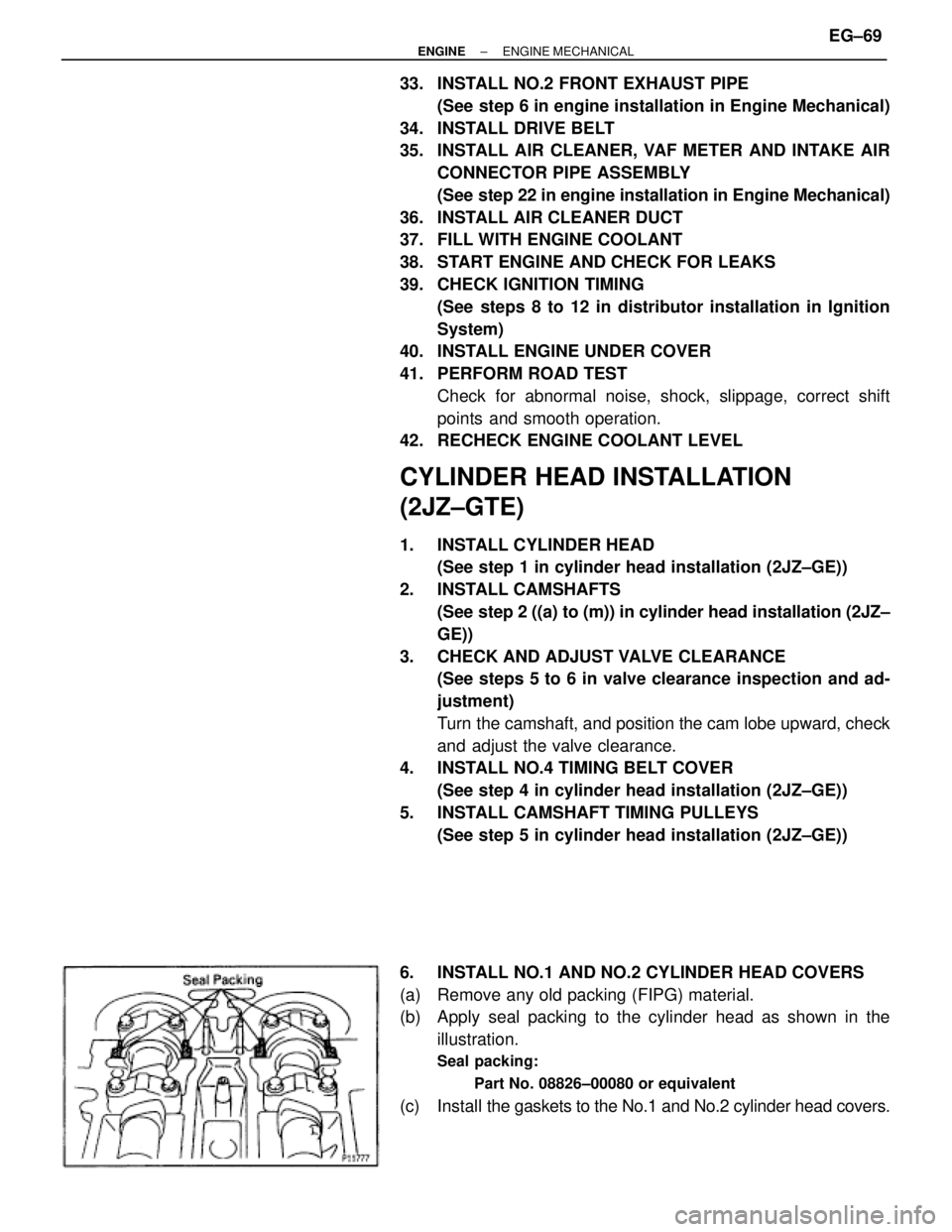
6. INSTALL NO.1 AND NO.2 CYLINDER HEAD COVERS
(a) Remove any old packing (FIPG) material.
(b) Apply seal packing to the cylinder head as shown in the
illustration.
Seal packing:
Part No. 08826±00080 or equivalent
(c) Install the gaskets to the No.1 and No.2 cylinder head covers.
± ENGINEENGINE MECHANICALEG±69
Page 482 of 878
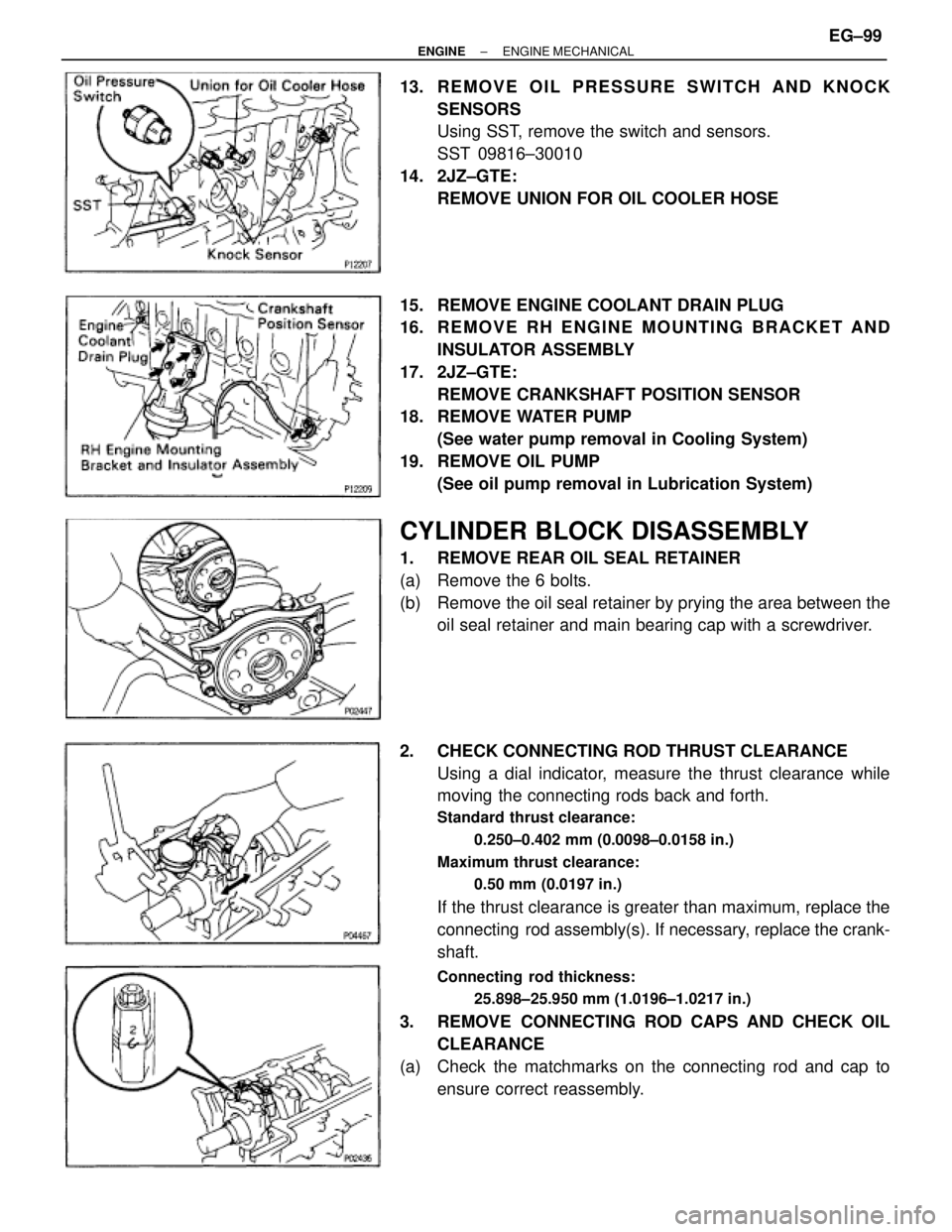
13. REMOVE OIL PRESSURE SWITCH AND KNOCK
SENSORS
Using SST, remove the switch and sensors.
SST 09816±30010
14. 2JZ±GTE:
REMOVE UNION FOR OIL COOLER HOSE
15. REMOVE ENGINE COOLANT DRAIN PLUG
16. R E M O V E R H E N G I N E M O U N T I N G B R A C K E T A N D
INSULATOR ASSEMBLY
17. 2JZ±GTE:
REMOVE CRANKSHAFT POSITION SENSOR
18. REMOVE WATER PUMP
(See water pump removal in Cooling System)
19. REMOVE OIL PUMP
(See oil pump removal in Lubrication System)
CYLINDER BLOCK DISASSEMBLY
1. REMOVE REAR OIL SEAL RETAINER
(a) Remove the 6 bolts.
(b) Remove the oil seal retainer by prying the area between the
oil seal retainer and main bearing cap with a screwdriver.
2. CHECK CONNECTING ROD THRUST CLEARANCE
Using a dial indicator, measure the thrust clearance while
moving the connecting rods back and forth.
Standard thrust clearance:
0.250±0.402 mm (0.0098±0.0158 in.)
Maximum thrust clearance:
0.50 mm (0.0197 in.)
If the thrust clearance is greater than maximum, replace the
connecting rod assembly(s). If necessary, replace the crank-
shaft.
Connecting rod thickness:
25.898±25.950 mm (1.0196±1.0217 in.)
3. REMOVE CONNECTING ROD CAPS AND CHECK OIL
CLEARANCE
(a) Check the matchmarks on the connecting rod and cap to
ensure correct reassembly.
± ENGINEENGINE MECHANICALEG±99
Page 504 of 878
AFTER ASSEMBLY
1. INSTALL OIL PUMP
(See oil pump installation in Lubrication System)
2. INSTALL WATER PUMP
(See water pump installation in Cooling System)
3. 2JZ±GTE:
INSTALL CRANKSHAFT POSITION SENSOR
Torque: 8.8 NVm (90 kgfVcm, 78 in.Vlbf)
4. INSTALL RH ENGINE MOUNTING BRACKET AND
INSULATOR ASSEMBLY
HINT: The RH mounting bracket is marked ºA u EXº.
Torque: 58 NVm (590 kgfVcm, 43 ftVlbf)
5. INSTALL ENGINE COOLANT DRAIN PLUG
Torque: 29 NVm (300 kgfVcm, 22 ftVlbf)
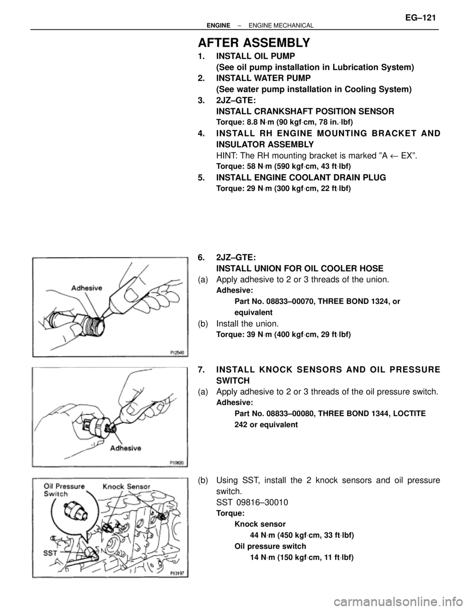
6. 2JZ±GTE:
INSTALL UNION FOR OIL COOLER HOSE
(a) Apply adhesive to 2 or 3 threads of the union.
Adhesive:
Part No. 08833±00070, THREE BOND 1324, or
equivalent
(b) Install the union.
Torque: 39 NVm (400 kgfVcm, 29 ftVlbf)
7. INSTALL KNOCK SENSORS AND OIL PRESSURE
SWITCH
(a) Apply adhesive to 2 or 3 threads of the oil pressure switch.
Adhesive:
Part No. 08833±00080, THREE BOND 1344, LOCTITE
242 or equivalent
(b) Using SST, install the 2 knock sensors and oil pressure
switch.
SST 09816±30010
Torque:
Knock sensor
44 NVm (450 kgfVcm, 33 ftVlbf)
Oil pressure switch
14 NVm (150 kgfVcm, 11 ftVlbf)
± ENGINEENGINE MECHANICALEG±121
Page 511 of 878
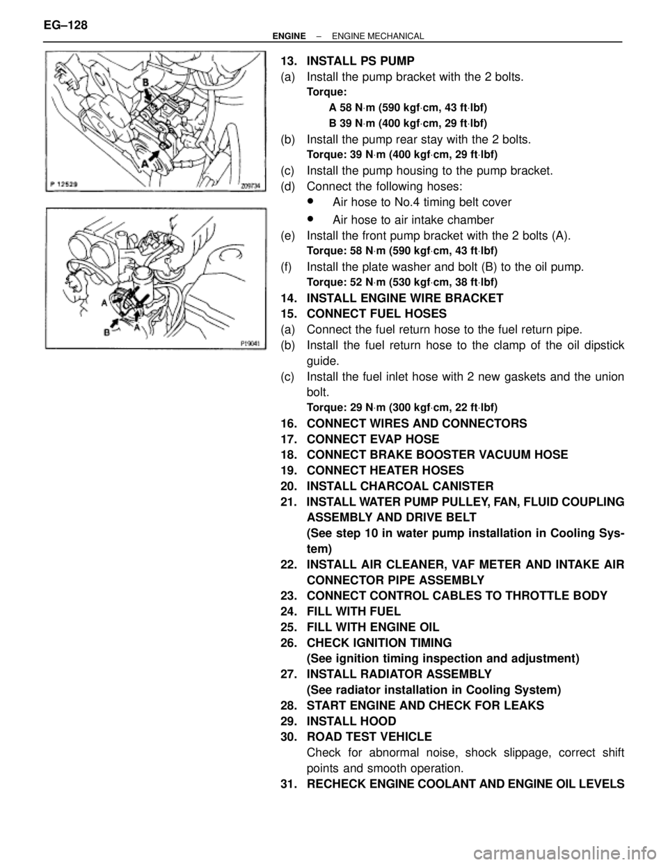
13. INSTALL PS PUMP
(a) Install the pump bracket with the 2 bolts.
Torque:
A 58 NVm (590 kgfVcm, 43 ftVlbf)
B 39 NVm (400 kgfVcm, 29 ftVlbf)
(b) Install the pump rear stay with the 2 bolts.
Torque: 39 NVm (400 kgfVcm, 29 ftVlbf)
(c) Install the pump housing to the pump bracket.
(d) Connect the following hoses:
wAir hose to No.4 timing belt cover
wAir hose to air intake chamber
(e) Install the front pump bracket with the 2 bolts (A).
Torque: 58 NVm (590 kgfVcm, 43 ftVlbf)
(f) Install the plate washer and bolt (B) to the oil pump.
Torque: 52 NVm (530 kgfVcm, 38 ftVlbf)
14. INSTALL ENGINE WIRE BRACKET
15. CONNECT FUEL HOSES
(a) Connect the fuel return hose to the fuel return pipe.
(b) Install the fuel return hose to the clamp of the oil dipstick
guide.
(c) Install the fuel inlet hose with 2 new gaskets and the union
bolt.
Torque: 29 NVm (300 kgfVcm, 22 ftVlbf)
16. CONNECT WIRES AND CONNECTORS
17. CONNECT EVAP HOSE
18. CONNECT BRAKE BOOSTER VACUUM HOSE
19. CONNECT HEATER HOSES
20. INSTALL CHARCOAL CANISTER
21. INSTALL WATER PUMP PULLEY, FAN, FLUID COUPLING
ASSEMBLY AND DRIVE BELT
(See step 10 in water pump installation in Cooling Sys-
tem)
22. INSTALL AIR CLEANER, VAF METER AND INTAKE AIR
CONNECTOR PIPE ASSEMBLY
23. CONNECT CONTROL CABLES TO THROTTLE BODY
24. FILL WITH FUEL
25. FILL WITH ENGINE OIL
26. CHECK IGNITION TIMING
(See ignition timing inspection and adjustment)
27. INSTALL RADIATOR ASSEMBLY
(See radiator installation in Cooling System)
28. START ENGINE AND CHECK FOR LEAKS
29. INSTALL HOOD
30. ROAD TEST VEHICLE
Check for abnormal noise, shock slippage, correct shift
points and smooth operation.
31. RECHECK ENGINE COOLANT AND ENGINE OIL LEVELS EG±128
± ENGINEENGINE MECHANICAL