Page 188 of 878
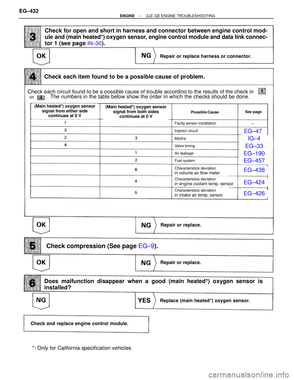
EG±47
2
IG±4
EG±33
EG±190
EG±457
EG±438
EG±424
EG±426
Check for open and short in harness and connector between engine control mod-
ule and (main heated*) oxygen sensor, engine control module and data link connec-
tor 1 (see page
IN±30).
Check each item found to be a possible cause of problem.
Repair or replace harness or connector.
Repair or replace.
Repair or replace.
Replace (main heated*) oxygen sensor.
Check and replace engine control module.
Does malfunction disappear when a good (main heated*) oxygen sensor is
installed?
Check compression (See page EG±9).
Check each circuit found to be a possible cause of trouble according to the results of the check in
The numbers in the table below show the order in which the checks should be done.
(Main heated*) oxygen sensor
signal from either side
continues at 0 V(Main heated*) oxygen sensor
signal from both sides
continues at 0 V
Possible CauseSee page
Faulty sensor installation
Injector circuit
Misfire
Valve timing
Air leakage
Fuel system
Characteristics deviation
in volume air flow meter
Characteristics deviation
in engine coolant temp. sensor
Characteristics deviation
in intake air temp. sensor
*: Only for California specification vehicles EG±432
± ENGINE2JZ±GE ENGINE TROUBLESHOOTING
Page 189 of 878
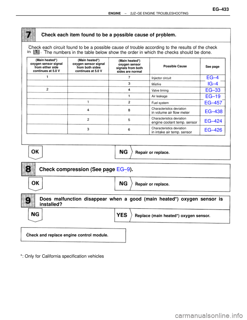
EG±4
72
IG±4
EG±33
EG±19
0
EG±457
EG±438
EG±424
EG±426
(See page EG±9).
Check each item found to be a possible cause of problem.
Repair or replace.
Check each circuit found to be a possible cause of trouble according to the results of the check
The numbers in the table below show the order in which the checks should be done.
(Main heated*)
oxygen sensor signal
from either side
continues at 5.0 V
Possible Cause
Injector circuit
Misfire
Valve timing
Air leakage
Fuel system
Characteristics deviation
in volume air flow meter
Characteristics deviation
in volume air flow meter
Characteristics deviation
engine coolant temp. sensor
(Main heated*)
oxygen sensor signal
from both sides
continues at 5.0 V(Main heated*)
oxygen sensor
signals from both
sides are normal
See page
Characteristics deviation
in intake air temp. sensor
Repair or replace.
Replace (main heated*) oxygen sensor.
Check and replace engine control module.
Does malfunction disappear when a good (main heated*) oxygen sensor is
installed?
Check compression (See page EG±9).
*: Only for California specification vehicles
± ENGINE2JZ±GE ENGINE TROUBLESHOOTINGEG±433
Page 190 of 878
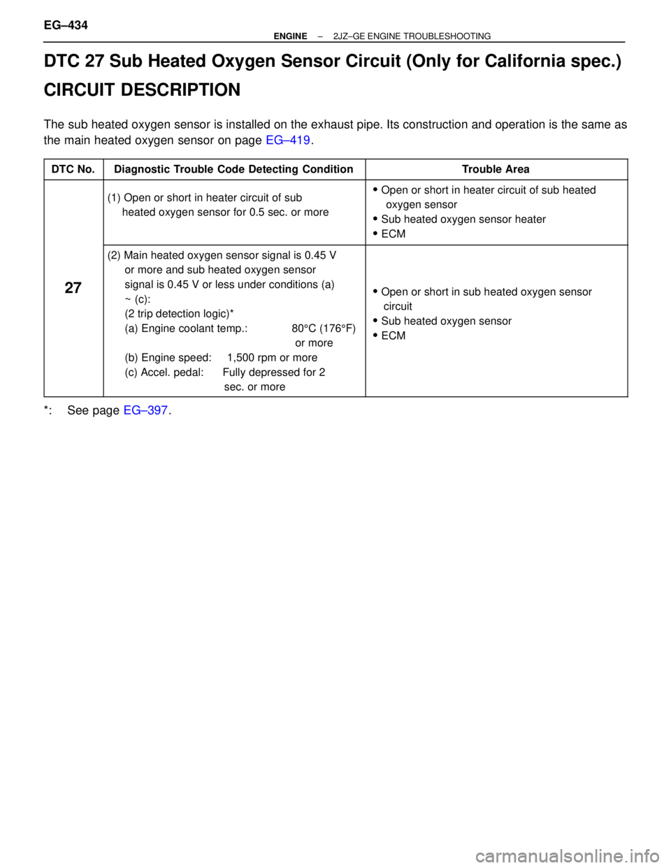
DTC 27 Sub Heated Oxygen Sensor Circuit (Only for California spec.)
CIRCUIT DESCRIPTION
The sub heated oxygen sensor is installed on the exhaust pipe. Its construction and operation is the same as
the main heated oxygen sensor on page EG±419.
����� �����DTC No.���������������� ����������������Diagnostic Trouble Code Detecting Condition����������������� �����������������Trouble Area
����� �
���� �
���� �
���� �����
���������������� �
��������������� �
��������������� �
��������������� ����������������
(1) Open or short in heater circuit of sub
heated oxygen sensor for 0.5 sec. or more
����������������� �
���������������� �
���������������� �
���������������� �����������������
� Open or short in heater circuit of sub heated
oxygen sensor
� Sub heated oxygen sensor heater
� ECM
����� �
���� �
���� �
���� �
���� �
���� �
���� �
���� �
���� �����
27
���������������� �
��������������� �
��������������� �
��������������� �
��������������� �
��������������� �
��������������� �
��������������� �
��������������� ����������������
(2) Main heated oxygen sensor signal is 0.45 V
or more and sub heated oxygen sensor
signal is 0.45 V or less under conditions (a)
~ (c):
(2 trip detection logic)*
(a) Engine coolant temp.: 805C (1765F)
or more
(b) Engine speed: 1,500 rpm or more
(c) Accel. pedal: Fully depressed for 2
sec. or more����������������� �
���������������� �
���������������� �
���������������� �
���������������� �
���������������� �
���������������� �
���������������� �
���������������� �����������������
� Open or short in sub heated oxygen sensor
circuit
� Sub heated oxygen sensor
� ECM
*: See page EG±397. EG±434
± ENGINE2JZ±GE ENGINE TROUBLESHOOTING
Page 199 of 878
INSPECTION PROCEDURE
HINT:
wIf diagnostic trouble code º22º (engine coolant temperature sensor circuit), º24º (intake air temperature
sensor circuit) and º41º (throttle position sensor circuit) are output simultaneously, E2 (sensor ground) may
be open.
(See page EG±219)
Check voltage between VTA1, IDL1 and E2 of engine control module connec-
tor.
(1) Connect SST (check harness ªAº).
(See page EG±404)
SST 09990±01000
(2) Turn ignition switch ON.
(3) Disconnect the vacuum hose from the throttle
body, then apply vacuum to the throttle opener.
(See page EG±219)
Measure voltage between terminals VTA1, IDL1
and E2 of engine control module connector when
the throttle valve is opened gradually from the
closed condition.
Check for intermittent problems.
(See page EG±399)
The voltage should increase steadily in proportion
to the throttle valve opening angle.
Terminal
Throttle Valve
Fully Closed
Fully Open
± ENGINE2JZ±GE ENGINE TROUBLESHOOTINGEG±443
Page 201 of 878
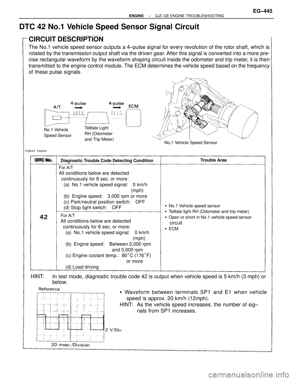
DTC 42 No.1 Vehicle Speed Sensor Signal Circuit
CIRCUIT DESCRIPTION
The No.1 vehicle speed sensor outputs a 4±pulse signal for every revolution of the rotor shaft, which is
rotated by the transmission output shaft via the driven gear. After this signal is converted into a more pre-
cise rectangular waveform by the waveform shaping circuit inside the odometer and trip meter, it is then
transmitted to the engine control module. The ECM determines the vehicle speed based on the frequency
of these pulse signals.
No.1 Vehicle
Speed SensorTelltale Light
RH (Odometer
and Trip Meter)
No.1 Vehicle Speed Sensor
DTC No.
Diagnostic Trouble Code Detecting ConditionTrouble Area
�No.1 Vehicle speed sensor
�Telltale light RH (Odometer and trip meter)
�Open or short in No.1 vehicle speed sensor
circuit
�ECM
For A/T
All conditions below are detected
continuously for 8 sec. or more:
(a) No.1 vehicle speed signal: 0 km/h
(mph)
(b) Engine speed: 3,000 rpm or more
(c) Park/neutral position switch: OFF
(d) Stop light switch: OFF
For A/T
All conditions below are detected
continuously for 8 sec. or more:
(a) No.1 vehicle speed signal: 0 km/h
(mph)
(b) Engine speed: Between 2,000 rpm
and 5,000 rpm
(c) Engine coolant temp.: 80°C (176°F)
or more
(d) Load driving
�Waveform between terminals SP1 and E1 when vehicle
speed is approx. 20 km/h (12mph).
HINT: As the vehicle speed increases, the number of sig±
nals from SP1 increases.
HINT: In test mode, diagnostic trouble code 42 is output when vehicle speed is 5 km/h (3 mph) or
below.
± ENGINE2JZ±GE ENGINE TROUBLESHOOTINGEG±445
Page 209 of 878
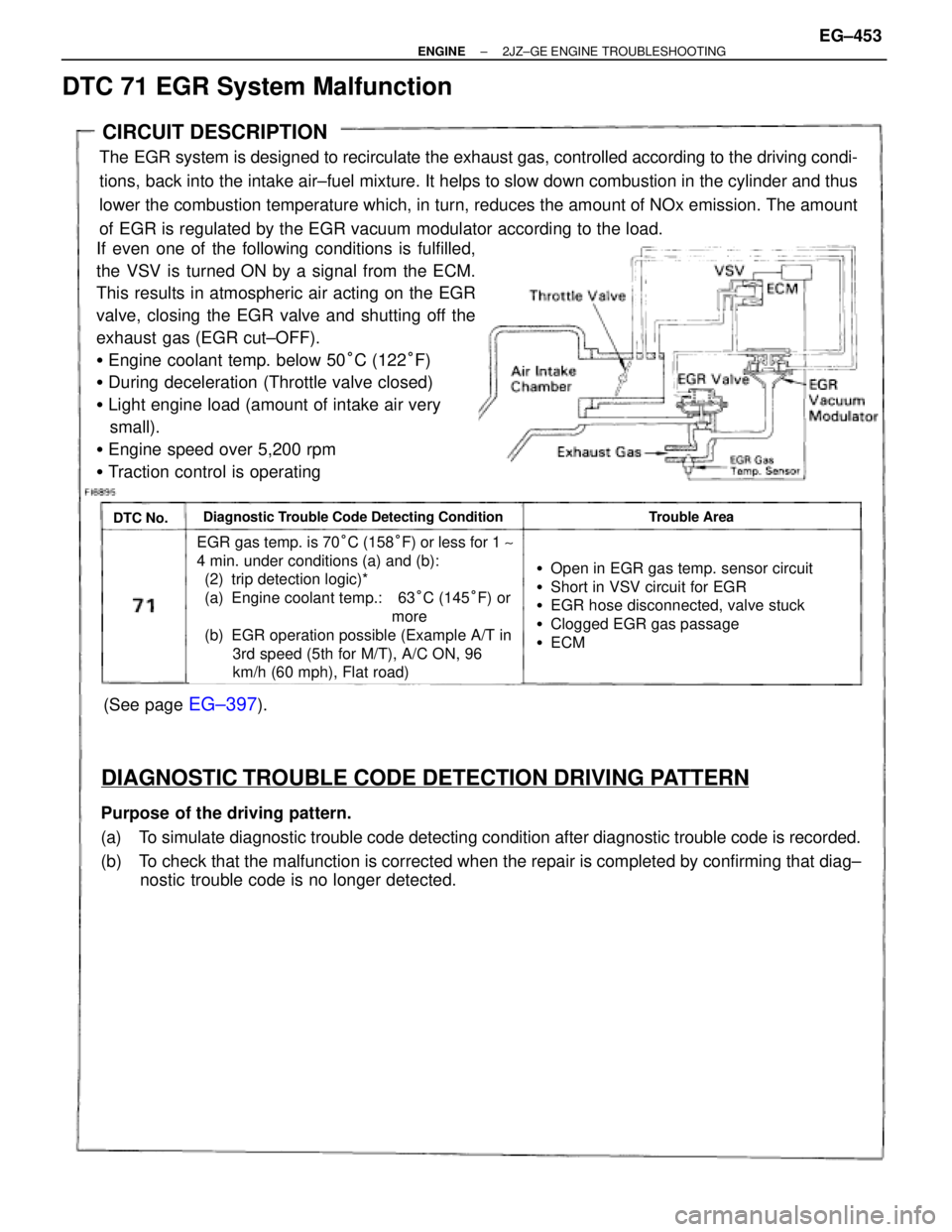
(See page EG±397).
CIRCUIT DESCRIPTION
The EGR system is designed to recirculate the exhaust gas, controlled according to the driving condi-
tions, back into the intake air±fuel mixture. It helps to slow down combustion in the cylinder and thus
lower the combustion temperature which, in turn, reduces the amount of NOx emission. The amount
of EGR is regulated by the EGR vacuum modulator according to the load.
If even one of the following conditions is fulfilled,
the VSV is turned ON by a signal from the ECM.
This results in atmospheric air acting on the EGR
valve, closing the EGR valve and shutting off the
exhaust gas (EGR cut±OFF).
�Engine coolant temp. below 50°C (122°F)
�During deceleration (Throttle valve closed)
�Light engine load (amount of intake air very
small).
�Engine speed over 5,200 rpm
�Traction control is operating
DTC No.Diagnostic Trouble Code Detecting ConditionTrouble Area
EGR gas temp. is 70°C (158°F) or less for 1 ~
4 min. under conditions (a) and (b):
(2) trip detection logic)*
(a) Engine coolant temp.: 63°C (145°F) or
more
(b) EGR operation possible (Example A/T in
3rd speed (5th for M/T), A/C ON, 96
km/h (60 mph), Flat road)
�Open in EGR gas temp. sensor circuit
�Short in VSV circuit for EGR
�EGR hose disconnected, valve stuck
�Clogged EGR gas passage
�ECM
DIAGNOSTIC TROUBLE CODE DETECTION DRIVING PATTERN
Purpose of the driving pattern.
(a) To simulate diagnostic trouble code detecting condition after diagnostic trouble code is recorded.
(b) To check that the malfunction is corrected when the repair is completed by confirming that diag±
nostic trouble code is no longer detected.
DTC 71 EGR System Malfunction
± ENGINE2JZ±GE ENGINE TROUBLESHOOTINGEG±453
Page 237 of 878
VSV Circuit for Fuel Pressure Control (Only for California spec.)
CIRCUIT DESCRIPTION
The ECM turns on a VSV (Vacuum Switching
Valve) to draw air into the diaphragm cham-
ber of the pressure regulator if it detects that
the temperature of the engine coolant is too
high during engine starting.
The air drawn into the chamber increases the
fuel pressure to prevent fuel vapor lock at
high engine temperature in order to help the
engine start when it is warm.
`Fuel pressure control ends approx. 120 sec.
after then engine is started.
± ENGINE2JZ±GE ENGINE TROUBLESHOOTINGEG±481
Page 243 of 878
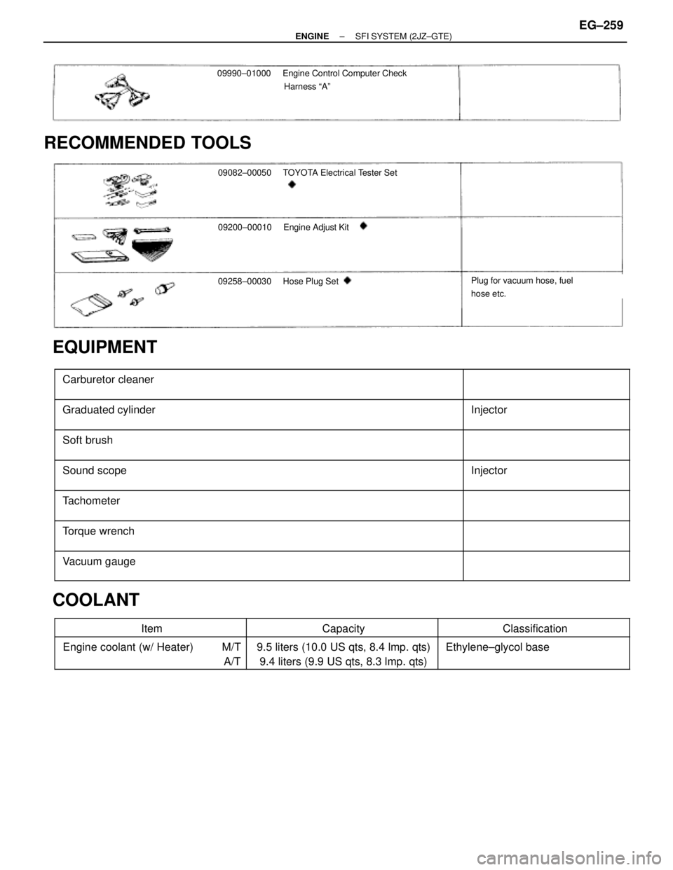
09990±01000Engine Control Computer Check
Harness ªAº
RECOMMENDED TOOLS
09082±00050 TOYOTA Electrical Tester Set
09200±00010Engine Adjust Kit
09258±00030 Hose Plug SetPlug for vacuum hose, fuel
hose etc.
EQUIPMENT
������������������������� �
������������������������ �������������������������Carburetor cleaner
����������� �
���������� �����������
������������������������� �
������������������������ �������������������������Graduated cylinder����������� �
���������� �����������Injector
������������������������� �
������������������������ �������������������������
Soft brush����������� �
���������� �����������
������������������������� �
������������������������ �������������������������
Sound scope����������� �
���������� �����������
Injector
������������������������� �������������������������Tachometer����������� �����������
������������������������� �
������������������������ �������������������������Torque wrench
����������� �
���������� �����������
������������������������� �
������������������������ �������������������������Vacuum gauge����������� �
���������� �����������
COOLANT
������������ ������������Item������������ ������������Capacity������������� �������������Classification������������ �
����������� ������������Engine coolant (w/ Heater) M/T
A/T������������ �
����������� ������������9.5 liters (10.0 US qts, 8.4 lmp. qts)
9.4 liters (9.9 US qts, 8.3 lmp. qts)������������� �
������������ �������������Ethylene±glycol base
± ENGINESFI SYSTEM (2JZ±GTE)EG±259