Page 730 of 2389
REMOVAL OF SAFETY PAD
(See pages BO±62, 63)
1. DISCONNECT BATTERY CABLE FROM NEGATIVE
TERMINAL
2. REMOVE STEERING WHEEL
3. REMOVE FRONT PILLAR GARNISH
Pry out the clips and pull the front pillar garnish upward
to remove it by the hand.
4. REMOVE NO. 1 UNDER COVER
5. REMOVE LOWER FINISH PANEL
(a) Remove the two screws and the engine. hood re-
lease lever. HINT: Screw sizes in the previous illustration are indi-
cated by following the code below for removal and
installation of safety pad.
mm (in.)
Shape
ShapeShapeCode
CodeCodeSizeSizeSize
± BODYSafety PadBO±64
Page 907 of 2389

ANTI±LOCK BRAKE SYSTEM (A.B.S.)
Description
wThe A.B.S. is a brake system which controls the wheel cylinder hydraulic pressure of all four wheels during
sudden braking and braking on slippery road surfaces, preventing the wheels from locking. This A.B.S.
provides the following benefits:
(1) Enables steering round an obstacle with a greater degree of certainty even when panic braking.
(2) Enables stopping in a panic brake while keeping the effect upon stability and steerability to a mini-
mum, even on curves.
wThe function of the A.B.S. is to help maintain directional stability and vehicle steerability on most road
conditions. However, the system cannot prevent the vehicle from skidding if the cornering speed limit is
exceeded.
wThe A.B.S. has a longitudinal deceleration sensor to match braking characteristics to the full±time four±
wheel drive. (For 4WD)
wIn case a malfunction occurs, a diagnosis function and fail±safe system have been adopted for the A.B.S.
to increase serviceability.
2WD (SEDAN)
± BRAKE SYSTEMAnti±lock Brake System (A.B.S.)BR±56
Page 1359 of 2389

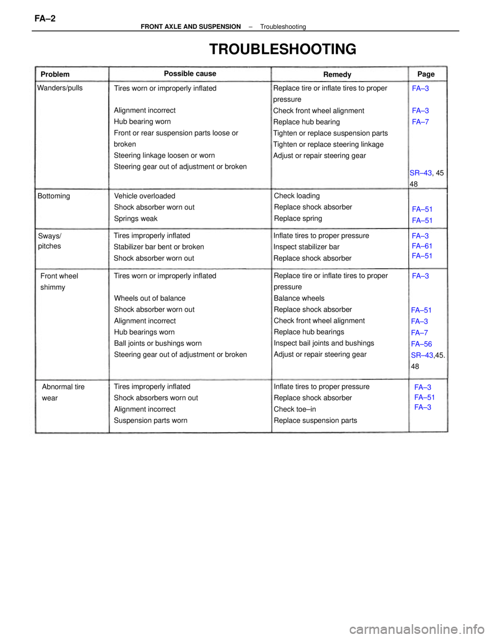
Replace tire or inflate tires to proper
pressure
Check front wheel alignment
Replace hub bearing
Tighten or replace suspension parts
Tighten or replace steering linkage
Adjust or repair steering gear
Replace tire or inflate tires to proper
pressure
Balance wheels
Replace shock absorber
Check front wheel alignment
Replace hub bearings
Inspect bail joints and bushings
Adjust or repair steering gear Wheels out of balance
Shock absorber worn out
Alignment incorrect
Hub bearings worn
Ball joints or bushings worn
Steering gear out of adjustment or broken Alignment incorrect
Hub bearing worn
Front or rear suspension parts loose or
broken
Steering linkage loosen or worn
Steering gear out of adjustment or broken
Inflate tires to proper pressure
Replace shock absorber
Check toe±in
Replace suspension parts Tires improperly inflated
Shock absorbers worn out
Alignment incorrect
Suspension parts wornInflate tires to proper pressure
Inspect stabilizer bar
Replace shock absorber Tires improperly inflated
Stabilizer bar bent or broken
Shock absorber worn outVehicle overloaded
Shock absorber worn out
Springs weakCheck loading
Replace shock absorber
Replace spring
FA±51
FA±3
FA±7
FA±56
SR±43,45.
48
TROUBLESHOOTING
Tires worn or improperly inflatedTires worn or improperly inflated
Abnormal tire
wear Front wheel
shimmyFA±3
FA±61
FA±51
FA±3
FA±51
FA±3 SR±43, 45
48 Possible cause
Sways/
pitches Wanders/pulls
FA±51
FA±51 BottomingFA±3
FA±7 Problem
RemedyPage
FA±3
FA±3
± FRONT AXLE AND SUSPENSIONTroubleshootingFA ± 2
Page 1360 of 2389

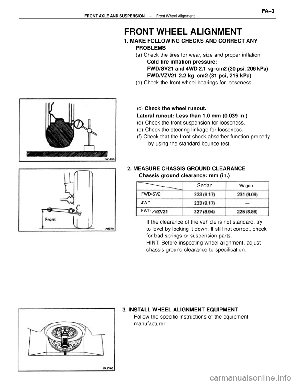
FRONT WHEEL ALIGNMENT
1. MAKE FOLLOWING CHECKS AND CORRECT ANY
PROBLEMS
(a) Check the tires for wear, size and proper inflation.
Cold tire inflation pressure:
FWD/SV21 and 4WD 2.1 kg±cm2 (30 psi, 206 kPa)
FWD/VZV21 2.2 kg±cm2 (31 psi, 216 kPa)
(b) Check the front wheel bearings for looseness.
(c) Check the wheel runout.
Lateral runout: Less than 1.0 mm (0.039 in.)
(d) Check the front suspension for looseness.
(e) Check the steering linkage for looseness.
(f) Check that the front shock absorber function properly
by using the standard bounce test.
If the clearance of the vehicle is not standard, try
to level by locking it down. If still not correct, check
for bad springs or suspension parts.
HINT: Before inspecting wheel alignment, adjust
chassis ground clearance to specification.
3. INSTALL WHEEL ALIGNMENT EQUIPMENT
Follow the specific instructions of the equipment
manufacturer. 2. MEASURE CHASSIS GROUND CLEARANCE
Chassis ground clearance: mm (in.)
FWD/SV21Wagon
Sedan
4WD
FWD
± FRONT AXLE AND SUSPENSIONFront Wheel AlignmentFA ± 3
Page 1361 of 2389

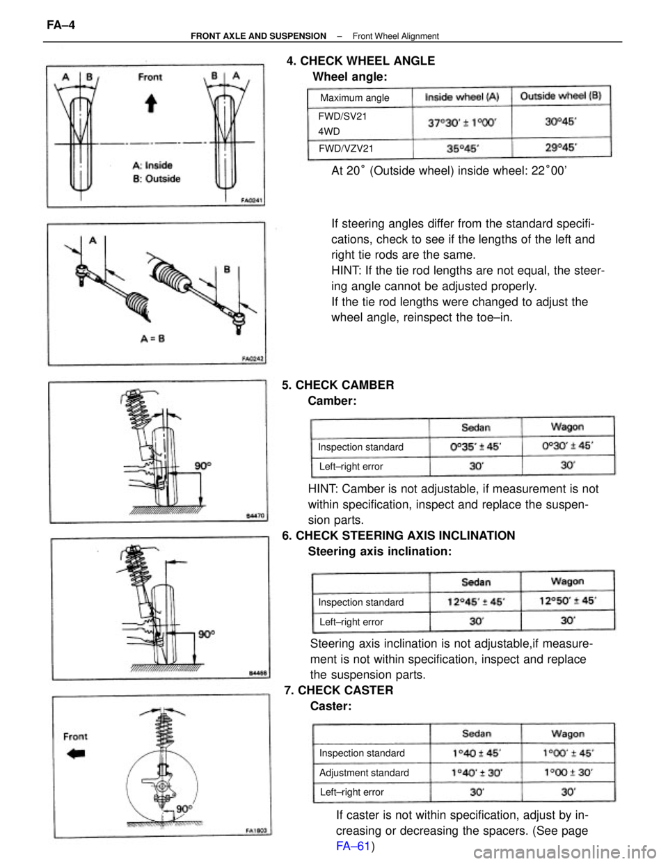
If steering angles differ from the standard specifi-
cations, check to see if the lengths of the left and
right tie rods are the same.
HINT: If the tie rod lengths are not equal, the steer-
ing angle cannot be adjusted properly.
If the tie rod lengths were changed to adjust the
wheel angle, reinspect the toe±in.
HINT: Camber is not adjustable, if measurement is not
within specification, inspect and replace the suspen-
sion parts.
6. CHECK STEERING AXIS INCLINATION
Steering axis inclination:
Steering axis inclination is not adjustable,if measure-
ment is not within specification, inspect and replace
the suspension parts.
7. CHECK CASTER
Caster:
If caster is not within specification, adjust by in-
creasing or decreasing the spacers. (See page
FA±61) At 20° (Outside wheel) inside wheel: 22°00' 4. CHECK WHEEL ANGLE
Wheel angle:
5. CHECK CAMBER
Camber:
Adjustment standard Inspection standard Inspection standard
Inspection standard FWD/SV21
4WDMaximum angle
Left±right error
Left±right error Left±right error FWD/VZV21
± FRONT AXLE AND SUSPENSIONFront Wheel AlignmentFA ± 4
Page 1371 of 2389
7. INSTALL BEARING LOCK NUT, LOCK NUT CAP AND
COTTER PIN
(a) Torque the bearing lock nut while depressing the brake
pedal.
Torque: 1,900 kg±cm (137 ft±lb , 186 N±m)
(b) Install the lock nut cap, and secure it with a new cotter
pin.
8. CHECK FRONT WHEEL ALIGNMENT
(See page FA ± 3)
REPLACEMENT OF FRONT AXLE HUB BOLT
1. MOVE DISC BRAKE CALIPER
Remove the disc brake caliper from the steering knuckle and
suspended it with wire.
2. REMOVE ROTOR DISC
3. REMOVE FRONT AXLE HUB BOLT
(a) Align the disc brake dust cover cutting portion and axle
hub bolt.
(b) Using SST, remove the axle hub bolt.
SST 09650±17011
6. INSTALL DISC BRAKE CALIPER TO STEERING
KNUCKLE
Torque: 1,190kg±cm (86 ft±lb , 117 N±m)
4. INSTALL FRONT AXLE HUB BOLT
(a) Hold the front axle hub, and install a new hub
bolt.
5. INSTALL ROTOR DISC
± FRONT AXLE AND SUSPENSIONFront Axle HubFA±14
Page 1397 of 2389
9. INSTALL BEARING LOCK NUT, LOCK NUT CAP AND
NEW COTTER PIN
(a) Torque the bearing lock nut while depressing the brake
pedal.
Torque: 1,900 kg±cm (137 ft±Ib, 186 N±m)
(b) Install the lock nut cap and, using pliers, install a new
cotter pin. 8. TIGHTEN SIX HEXAGON BOLTS
Using SST, tighten the six hexagon bolts while depress-
ing the brake pedal.
SST 09043±88010
Torque: 660 kg±cm (48 ft±Ib, 65 N±m)
10. FILL TRANSAXLE WITH GEAR OIL
(See page MT±45)
11. INSTALL ENGINE UNDER COVERS
12. CHECK FRONT WHEEL ALIGNMENT7. CONNECT STEERING KNUCKLE TO LOWER ARM
Torque: 1,150 kg±cm (83 ft±Ib, 113 N±m)
± FRONT AXLE AND SUSPENSIONFront Drive Shaft (FWD VZV21 )FA±40
Page 1407 of 2389
6. FILL TRANSAXLE WITH GEAR OIL OR FLUID
M/T (See page MT±1 17)
A/T Fluid type: ATF DEXRON) II
7. INSTALL ENGINE UNDER COVERS
8. INSTALL WHEELS
9. CHECK FRONT WHEEL ALIGNMENT
(See page FA ± 3) 5. INSTALL BEARING LOCK NUT, LOCK NUT CAP AND
COTTER PIN
(a) Torque the bearing lock nut while depressing the brake
pedal.
Torque: 1, 900 kg±cm (137 ft±Ib, 186 N±m )
(b) Install the lock nut cap and, using pliers, install a new
cotter pin. 4. CONNECT TIE ROD END TO STEERING KNUCKLE
Install and torque the nut, and secure it with a new cotter pin.
Torque: 500 kg±cm (36 ft±Ib, 49 N±m)
± FRONT AXLE AND SUSPENSIONFront Drive Shaft (4WD)FA±50