1986 TOYOTA CAMRY V20 steering wheel
[x] Cancel search: steering wheelPage 2336 of 2389
SERVICE HINT
Troubles with the power steering system are usually
concerned with hard steering due to the fact that
there is no assist. In such cases, before attempting
to make repairs, it is necessary to determine wheth-
er the trouble lies with the pump or with the gear
housing. To do this, an on±vehicle inspection can be
made by using a pressure gauge.
ON±VEHICLE INSPECTION
Power steering is a hydraulic device and problems
are normally due to insufficient fluid pressure acting
on the piston. This could be caused by either the
pump not producing the specified fluid pressure or
the control valve in the gear housing not functioning
properly so that the proper fluid pressure can not be
obtained.
If the fault lies with the pump, the same symptoms
will generally occur whether the steering wheel is
turned fully to the right or left. On the other hand, if
the fault lies with the control valve, there will gener-
ally be difference between the amount of assist
when the steering wheel is turned to the left and
right, causing harder steering. However, if the piston
seal of the power cylinder is worn, there will be a
loss of fluid pressure whether the steering wheel is
turned to the right or left and the symptoms will be
the same for both.
Before performing an on±vehicle inspection, a
check must first be made to confirm that the power
steering system is completely free of any air. If there
is any air in the system, the volume of this air wilt
change when the fluid pressure raised, causing a
fluctuation in the fluid pressure so that the power
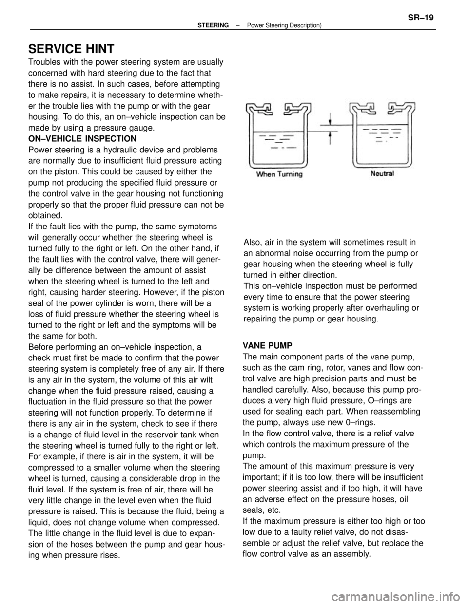
steering will not function properly. To determine if
there is any air in the system, check to see if there
is a change of fluid level in the reservoir tank when
the steering wheel is turned fully to the right or left.
For example, if there is air in the system, it will be
compressed to a smaller volume when the steering
wheel is turned, causing a considerable drop in the
fluid level. If the system is free of air, there will be
very little change in the level even when the fluid
pressure is raised. This is because the fluid, being a
liquid, does not change volume when compressed.
The little change in the fluid level is due to expan-
sion of the hoses between the pump and gear hous-
ing when pressure rises.VANE PUMP
The main component parts of the vane pump,
such as the cam ring, rotor, vanes and flow con-
trol valve are high precision parts and must be
handled carefully. Also, because this pump pro-
duces a very high fluid pressure, O±rings are
used for sealing each part. When reassembling
the pump, always use new 0±rings.
In the flow control valve, there is a relief valve
which controls the maximum pressure of the
pump.
The amount of this maximum pressure is very
important; if it is too low, there will be insufficient
power steering assist and if too high, it will have
an adverse effect on the pressure hoses, oil
seals, etc.
If the maximum pressure is either too high or too
low due to a faulty relief valve, do not disas-
semble or adjust the relief valve, but replace the
flow control valve as an assembly.Also, air in the system will sometimes result in
an abnormal noise occurring from the pump or
gear housing when the steering wheel is fully
turned in either direction.
This on±vehicle inspection must be performed
every time to ensure that the power steering
system is working properly after overhauling or
repairing the pump or gear housing.
± STEERINGPower Steering Description)SR±19
Page 2338 of 2389
IDLE±UP DEVICE
The pump produces the maximum fluid pressure
when the steering wheel is turned fully to the
right or left and, at this time, there is a maximum
load on
the pump which causes a decrease in engine
idle rpm. To solve this problem, vehicles are
equipped with an idle±up device which acts to
raise the engine idle rpm whenever there is a
heavy load on
the pump. As with the rack and pinion type steering, preload
is very important. If the preload is not correct, it
could result in such trouble as steering wheel play
or shimmy or lack of durability, so always make
sure that it is correct.
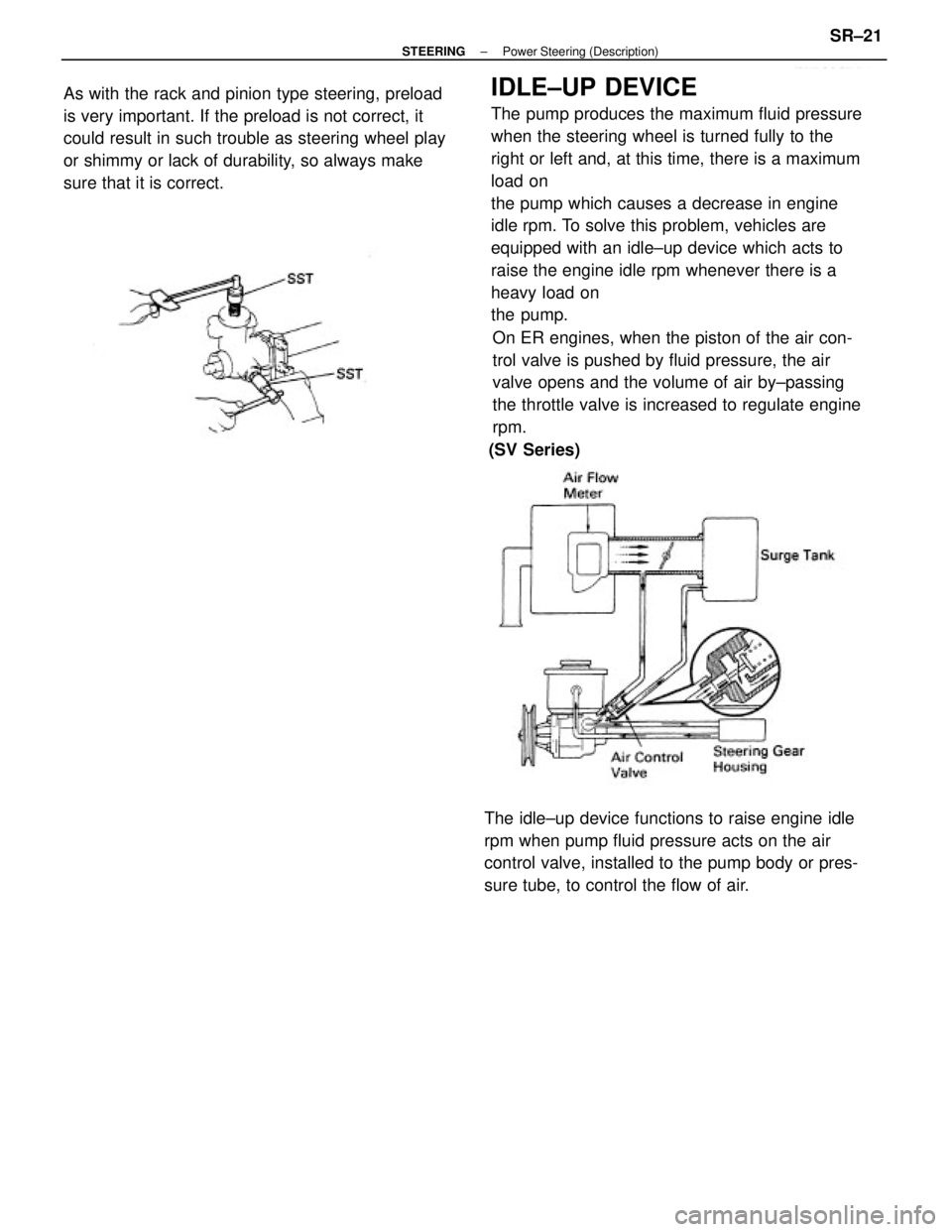
On ER engines, when the piston of the air con-
trol valve is pushed by fluid pressure, the air
valve opens and the volume of air by±passing
the throttle valve is increased to regulate engine
rpm.
The idle±up device functions to raise engine idle
rpm when pump fluid pressure acts on the air
control valve, installed to the pump body or pres-
sure tube, to control the flow of air.(SV Series)
± STEERINGPower Steering (Description)SR±21
Page 2348 of 2389
3. CHECK FOR FOAMING OR EMULSIFICATION
HINT: Foaming and emulsification indicate either the exis-
tence of air in the system or that the fluid level is too low.
4. CHECK FLUID LEVEL IN RESERVOIR
Check the fluid level and add fluid if necessary.
Fluid: ATF DEXRON II
HINT: Check that the fluid level is within the HOT LEVEL
of the tank. If the fluid is cold, check that it is within the
COLD LEVEL of the tank.
CHECK IDLE±UP
1. WARM UP ENGINE
2. TURN AIR CONDITIONER SWITCH OFF
3. CHECK IDLE±UP
(a) Fully turn the steering wheel.
(b) Check that the engine rpm decreases when the air
control valve hose is pinched.
(c) Check that the engine rpm increases when the air
control valve hose is released.
On±Vehicle Inspection
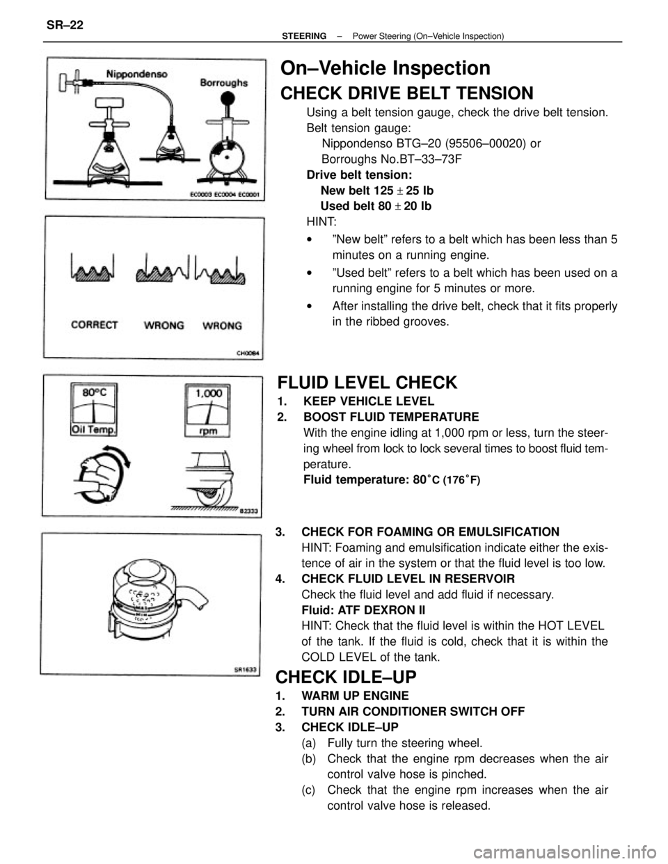
CHECK DRIVE BELT TENSION
Using a belt tension gauge, check the drive belt tension.
Belt tension gauge:
Nippondenso BTG±20 (95506±00020) or
Borroughs No.BT±33±73F
Drive belt tension:
New belt 125
+25 Ib
Used belt 80
+20 Ib
HINT:
wºNew beltº refers to a belt which has been less than 5
minutes on a running engine.
wºUsed beltº refers to a belt which has been used on a
running engine for 5 minutes or more.
wAfter installing the drive belt, check that it fits properly
in the ribbed grooves.
FLUID LEVEL CHECK
1. KEEP VEHICLE LEVEL
2. BOOST FLUID TEMPERATURE
With the engine idling at 1,000 rpm or less, turn the steer-
ing wheel from lock to lock several times to boost fluid tem-
perature.
Fluid temperature: 80
°C (176°F)
± STEERINGPower Steering (On±Vehicle Inspection)SR±22
Page 2349 of 2389
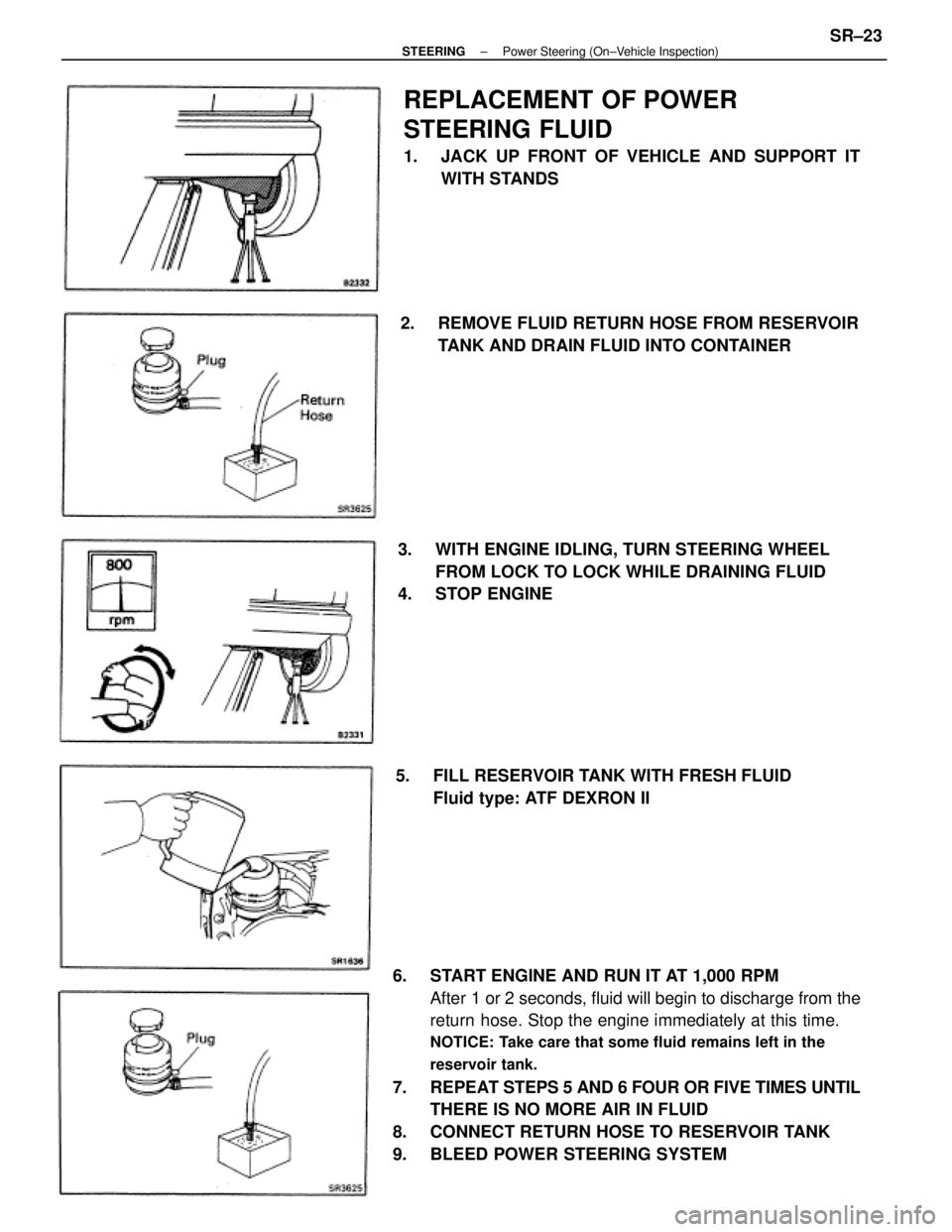
6. START ENGINE AND RUN IT AT 1,000 RPM
After 1 or 2 seconds, fluid will begin to discharge from the
return hose. Stop the engine immediately at this time.
NOTICE: Take care that some fluid remains left in the
reservoir tank.
7. REPEAT STEPS 5 AND 6 FOUR OR FIVE TIMES UNTIL
THERE IS NO MORE AIR IN FLUID
8. CONNECT RETURN HOSE TO RESERVOIR TANK
9. BLEED POWER STEERING SYSTEM
REPLACEMENT OF POWER
STEERING FLUID
1. JACK UP FRONT OF VEHICLE AND SUPPORT IT
WITH STANDS
3. WITH ENGINE IDLING, TURN STEERING WHEEL
FROM LOCK TO LOCK WHILE DRAINING FLUID
4. STOP ENGINE2. REMOVE FLUID RETURN HOSE FROM RESERVOIR
TANK AND DRAIN FLUID INTO CONTAINER
5. FILL RESERVOIR TANK WITH FRESH FLUID
Fluid type: ATF DEXRON II
± STEERINGPower Steering (On±Vehicle Inspection)SR±23
Page 2350 of 2389
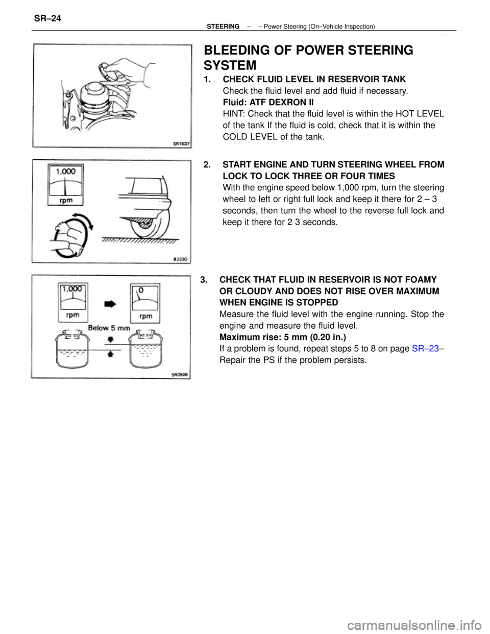
3. CHECK THAT FLUID IN RESERVOIR IS NOT FOAMY
OR CLOUDY AND DOES NOT RISE OVER MAXIMUM
WHEN ENGINE IS STOPPED
Measure the fluid level with the engine running. Stop the
engine and measure the fluid level.
Maximum rise: 5 mm (0.20 in.)
If a problem is found, repeat steps 5 to 8 on page SR±23±
Repair the PS if the problem persists.
BLEEDING OF POWER STEERING
SYSTEM
1. CHECK FLUID LEVEL IN RESERVOIR TANK
Check the fluid level and add fluid if necessary.
Fluid: ATF DEXRON II
HINT: Check that the fluid level is within the HOT LEVEL
of the tank If the fluid is cold, check that it is within the
COLD LEVEL of the tank.
2. START ENGINE AND TURN STEERING WHEEL FROM
LOCK TO LOCK THREE OR FOUR TIMES
With the engine speed below 1,000 rpm, turn the steering
wheel to left or right full lock and keep it there for 2 ± 3
seconds, then turn the wheel to the reverse full lock and
keep it there for 2 3 seconds.
± STEERING± Power Steering (On±Vehicle Inspection)SR±24
Page 2351 of 2389
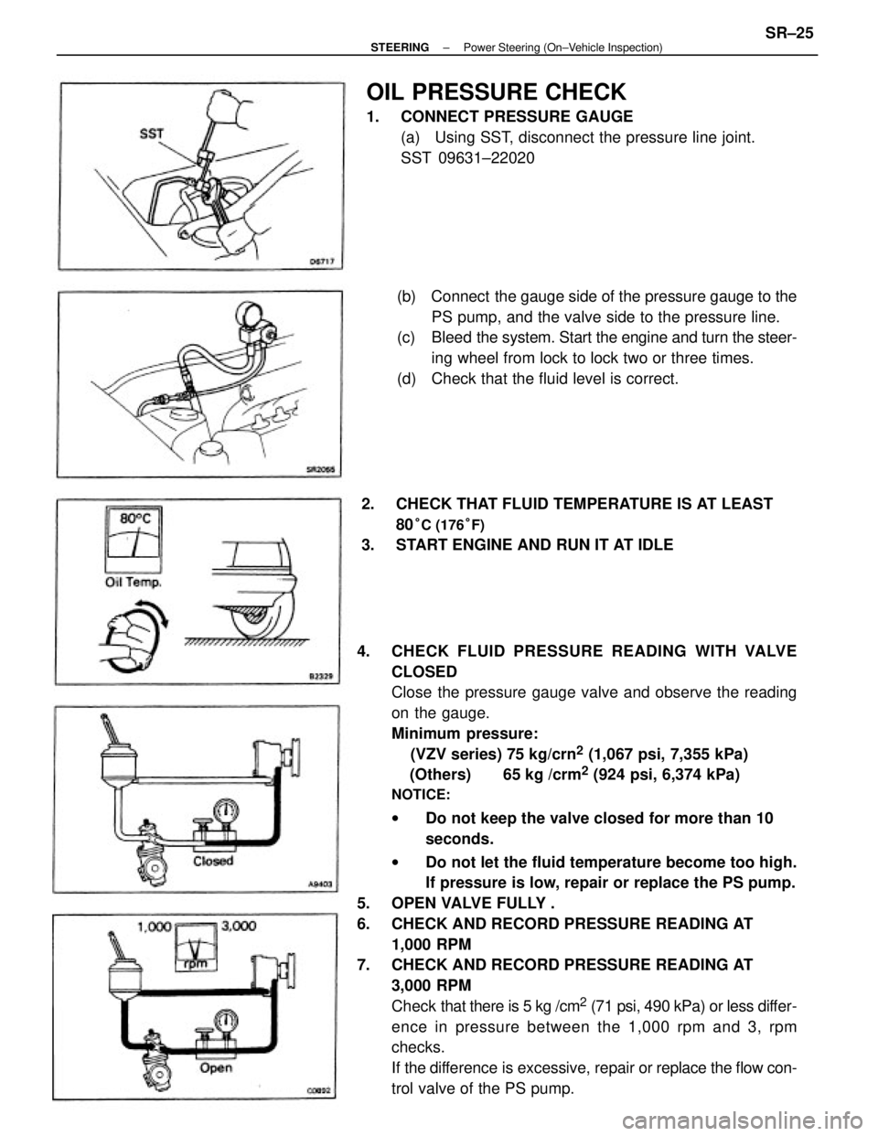
4. CHECK FLUID PRESSURE READING WITH VALVE
CLOSED
Close the pressure gauge valve and observe the reading
on the gauge.
Minimum pressure:
(VZV series) 75 kg/crn
2 (1,067 psi, 7,355 kPa)
(Others) 65 kg /crm
2 (924 psi, 6,374 kPa)
NOTICE:
wDo not keep the valve closed for more than 10
seconds.
wDo not let the fluid temperature become too high.
If pressure is low, repair or replace the PS pump.
5. OPEN VALVE FULLY .
6. CHECK AND RECORD PRESSURE READING AT
1,000 RPM
7. CHECK AND RECORD PRESSURE READING AT
3,000 RPM
Check that there is 5 kg /cm
2 (71 psi, 490 kPa) or less differ-
ence in pressure between the 1,000 rpm and 3, rpm
checks.
If the difference is excessive, repair or replace the flow con-
trol valve of the PS pump.(b) Connect the gauge side of the pressure gauge to the
PS pump, and the valve side to the pressure line.
(c) Bleed the system. Start the engine and turn the steer-
ing wheel from lock to lock two or three times.
(d) Check that the fluid level is correct.
OIL PRESSURE CHECK
1. CONNECT PRESSURE GAUGE
(a) Using SST, disconnect the pressure line joint.
SST 09631±22020
2. CHECK THAT FLUID TEMPERATURE IS AT LEAST
80
°C (176°F)
3. START ENGINE AND RUN IT AT IDLE
± STEERINGPower Steering (On±Vehicle Inspection)SR±25
Page 2352 of 2389
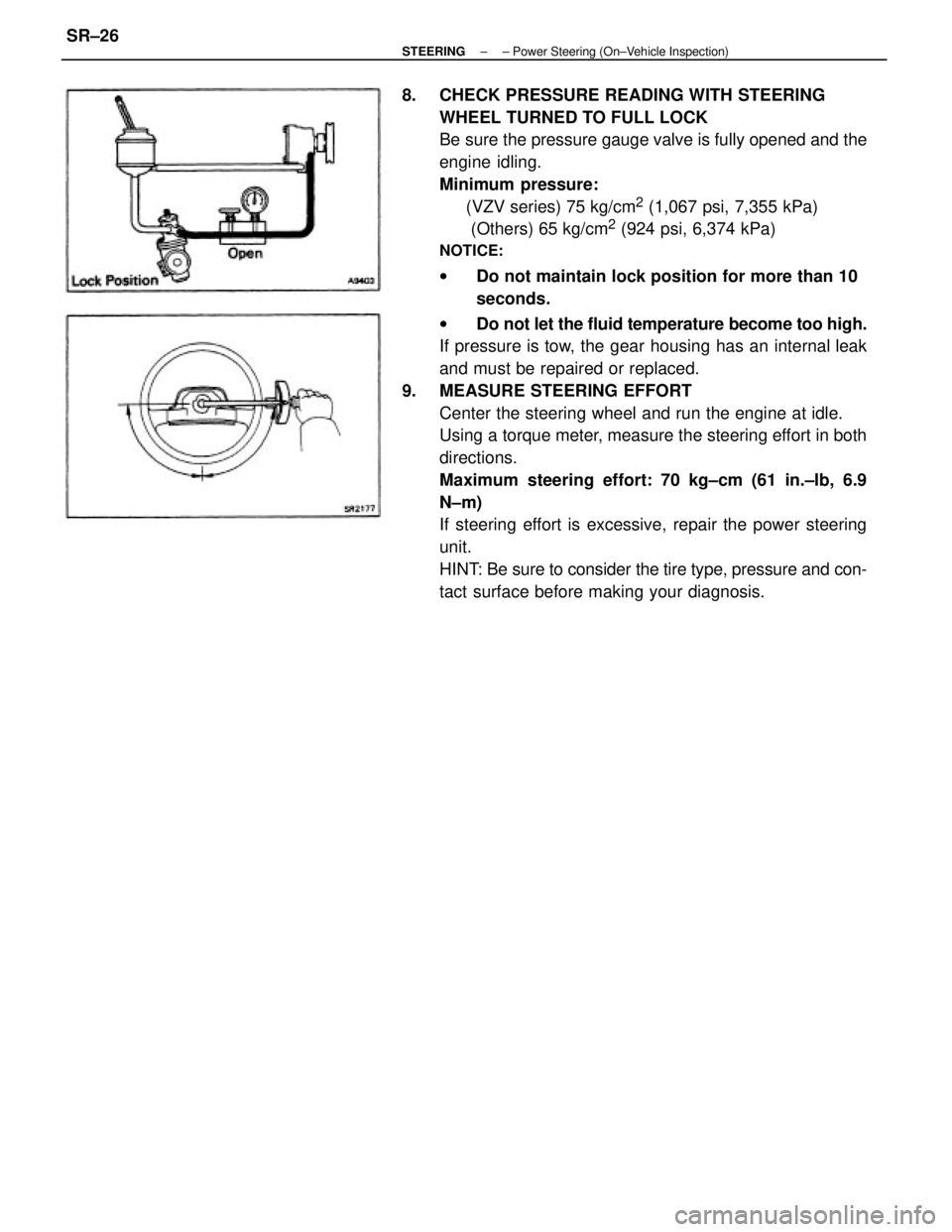
8. CHECK PRESSURE READING WITH STEERING
WHEEL TURNED TO FULL LOCK
Be sure the pressure gauge valve is fully opened and the
engine idling.
Minimum pressure:
(VZV series) 75 kg/cm
2 (1,067 psi, 7,355 kPa)
(Others) 65 kg/cm
2 (924 psi, 6,374 kPa)
NOTICE:
wDo not maintain lock position for more than 10
seconds.
wDo not let the fluid temperature become too high.
If pressure is tow, the gear housing has an internal leak
and must be repaired or replaced.
9. MEASURE STEERING EFFORT
Center the steering wheel and run the engine at idle.
Using a torque meter, measure the steering effort in both
directions.
Maximum steering effort: 70 kg±cm (61 in.±Ib, 6.9
N±m)
If steering effort is excessive, repair the power steering
unit.
HINT: Be sure to consider the tire type, pressure and con-
tact surface before making your diagnosis.
± STEERING± Power Steering (On±Vehicle Inspection)SR±26
Page 2388 of 2389
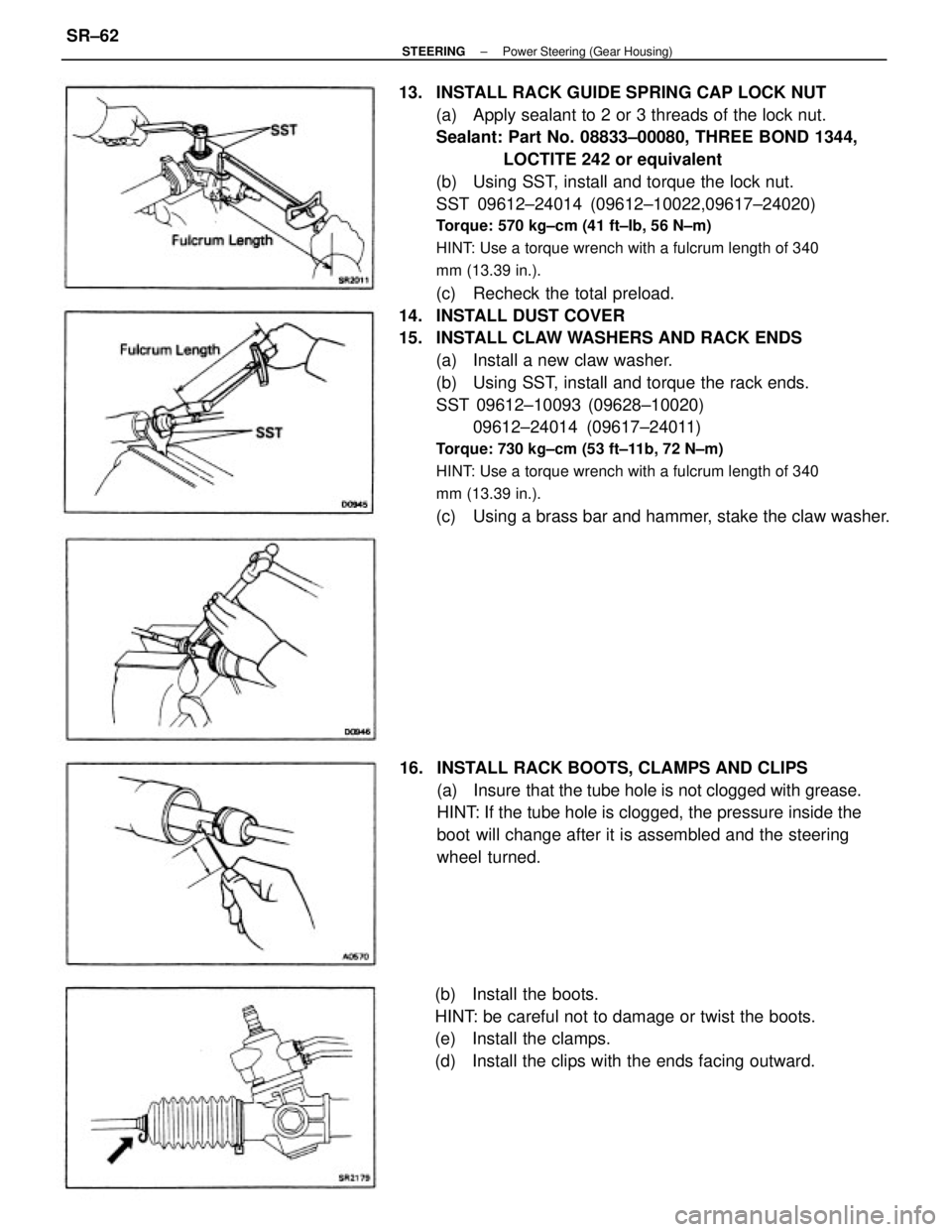
13. INSTALL RACK GUIDE SPRING CAP LOCK NUT
(a) Apply sealant to 2 or 3 threads of the lock nut.
Sealant: Part No. 08833±00080, THREE BOND 1344,
LOCTITE 242 or equivalent
(b) Using SST, install and torque the lock nut.
SST 09612±24014 (09612±10022,09617±24020)
Torque: 570 kg±cm (41 ft±Ib, 56 N±m)
HINT: Use a torque wrench with a fulcrum length of 340
mm (13.39 in.).
(c) Recheck the total preload.
14. INSTALL DUST COVER
15. INSTALL CLAW WASHERS AND RACK ENDS
(a) Install a new claw washer.
(b) Using SST, install and torque the rack ends.
SST 09612±10093 (09628±10020)
09612±24014 (09617±24011)
Torque: 730 kg±cm (53 ft±11b, 72 N±m)
HINT: Use a torque wrench with a fulcrum length of 340
mm (13.39 in.).
(c) Using a brass bar and hammer, stake the claw washer.
16. INSTALL RACK BOOTS, CLAMPS AND CLIPS
(a) Insure that the tube hole is not clogged with grease.
HINT: If the tube hole is clogged, the pressure inside the
boot will change after it is assembled and the steering
wheel turned.
(b) Install the boots.
HINT: be careful not to damage or twist the boots.
(e) Install the clamps.
(d) Install the clips with the ends facing outward.
± STEERINGPower Steering (Gear Housing)SR±62