Page 1416 of 2389
4. INSTALL SUSPENSION LOWER CROSSMEMBER
Temporarily install the two bolts and two nuts by hand,
and then torque the bolts and nuts.
Torque: 2,110 kg±cm (153 ft±Ib, 207 N±m)
HINT: Temporarily first install the lower arm shaft to the
body with lower arm shaft installation bolt and nut and
then temporarily install the suspension lower cross-
member. 3. CONNECT LOWER BALL JOINT TO STEERING
KNUCKLE
Connect the steering knuckle to the lower ball joint and
torque the two bolts.
Torque: 1,150 kg±cm (83 ft±Ib, 113 N ± m )
5. INSTALL WHEELS AND LOWER VEHICLE
(a) Install the wheels.
(b) Remove the stands and bounce the vehicle up and
down to stabilize the suspension.
6. TORQUE LOWER SUSPENSION ARM INSTALLATION
NUT
Torque: Stabilizer bar X Lower suspension arm
2,160 kg±cm (156 ft±Ib, 212 N±m)
Torque: Lower arm shaft x Lower suspension arm
2,160 kg±cm (156 ft±lb , 212 N±m)
7. CHECK FRONT WHEEL ALIGNMENT
± FRONT AXLE AND SUSPENSIONFront SuspensionFA±59
Page 1914 of 2389
GENERAL MAINTENANCE
These are the maintenance and inspection items
which are considered to be the owner's responsibility,
They can be performed by the owner or he
can have then done at a service shop. These items
include those which should be checked on a daily ba-
sis, those which, in most cases, do not require
(special) tools and those which are considered to be
reasonable for the owner to perform.
Items and procedures for general maintenance are as
follows:
OUTSIDE VEHICLE
1. TIRES
(a) Check the pressure with a gauge. Adjust
if necessary.
(b) Check for cuts, damage or excessive wear.
2. WHEEL NUTS
When checking the tires, check the nuts for looseness
or for missing nuts. If necessary,
tighten them.
3. TIRE ROTATION
It is recommended that tires be rotated every
7,500 miles (12,000 km).
4. WINDSHIELD WIPER BLADES
Check for wear or cracks whenever they do not wipe
clean. Replace if necessary.
5. FLUID LEAKS
(a) Check underneath for leaking fuel, oil, water or
other fluid.
(b) If you smell gasoline fumes or notice any leak,
have the cause found and corrected.
6. DOORS AND ENGINE HOOD
(a) Check that all doors including the trunk lid and
back door operate smoothly, and that all
latches lock securely.
(b) Check that the engine hood secondary latch se-
cures the hood from opening when the prima-
ry latch is released.
INSIDE VEHICLE
7. LIGHTS
(a) Check that the headlights, stop lights, taillights,
turn signal lights, and other
lights are all working.
(b) Check the headlight aiming.8. WARNING LIGHTS AND BUZZERS
Check that all warning lights and buzzers func-
tion properly.
9. HORN
Check that it is working.
10. WINDSHIELD GLASS
Check for scratches, pits or abrasions.
11. WINDSHIELD WIPER AND WASHER
(a) Check operation of the wipers and washer.
(b) Check that the wipers do not streak.
12. WINDSHIELD DEFROSTER
Check that air comes out from the defroster out-
let when operating the heater or air conditioner
at defroster mode.
13. REAR VIEW MIRROR
Check that it is mounted securely.
14. SUN VISORS
Check that they move freely and are mounted
securely.
15. STEERING WHEEL
Check that it has the specified freeplay. Be alert
for changes in steering condition, such as hard
steering, excessive freeplay or strange noise.
16. SEATS
(a) Check that all front seat controls such as
seat adjusters, seatback recliner, etc.
operate smoothly.
(b) Check that a11 latches lock securely in
any position.
(c) Check that the locks hold securely in any
latched position.
(d) Check that the head restraints move up
and down smoothly and that the locks
hold securely in any latched position.
(e) For folding±down rear seat backs, check
that the latches lock securely.
17. SEAT BELTS
(a) Check that the seat belt system such as
buckles, retractors and anchors operate
properly and smoothly.
(b) Check that the belt webbing is not cut,
frayed, worn or damaged.
± MAINTENANCEGeneral MaintenanceMA±16
Page 1920 of 2389
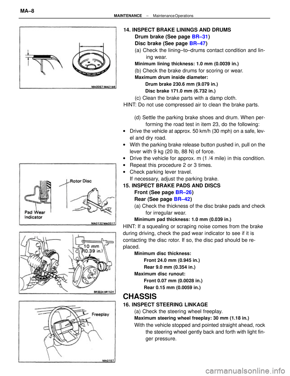
(d) Settle the parking brake shoes and drum. When per-
forming the road test in item 23, do the following:
wDrive the vehicle at approx. 50 km/h (30 mph) on a safe, lev-
el and dry road.
wWith the parking brake release button pushed in, pull on the
lever with 9 kg (20 Ib, 88 N) of force.
wDrive the vehicle for approx. m (1 /4 mile) in this condition.
wRepeat this procedure 2 or 3 times.
wCheck parking lever travel.
If necessary, adjust the parking brake.
15. INSPECT BRAKE PADS AND DISCS
Front (See page BR±26)
Rear (See page BR±42)
(a) Check the thickness of the disc brake pads and check
for irregular wear.
Minimum pad thickness: 1.0 mm (0.039 in.)
HINT: If a squealing or scraping noise comes from the brake
during driving, check the pad wear indicator to see if it is
contacting the disc rotor. If so, the disc pad should be re-
placed.
Minimum disc thickness:
Front 24.0 mm (0.945 in.)
Rear 9.0 mm (0.354 in.)
Maximum disc runout:
Front 0.07 mm (0.0028 in.)
Rear 0.15 mm (0.0059 in.)
CHASSIS
16. INSPECT STEERING LINKAGE
(a) Check the steering wheel freeplay.
Maximum steering wheel freeplay: 30 mm (1.18 in.)
With the vehicle stopped and pointed straight ahead, rock
the steering wheel gently back and forth with light fin-
ger pressure. 14. INSPECT BRAKE LININGS AND DRUMS
Drum brake (See page BR±31)
Disc brake (See page BR±47)
(a) Check the lining±to±drums contact condition and lin-
ing wear.
Minimum lining thickness: 1.0 mm (0.0039 in.)
(b) Check the brake drums for scoring or wear.
Maximum drum inside diameter:
Drum brake 230.6 mm (9.079 in.)
Disc brake 171.0 mm (6.732 in.)
(c) Clean the brake parts with a damp cloth.
HINT: Do not use compressed air to clean the brake parts.
± MAINTENANCEMaintenance OperationsMA±8
Page 1921 of 2389
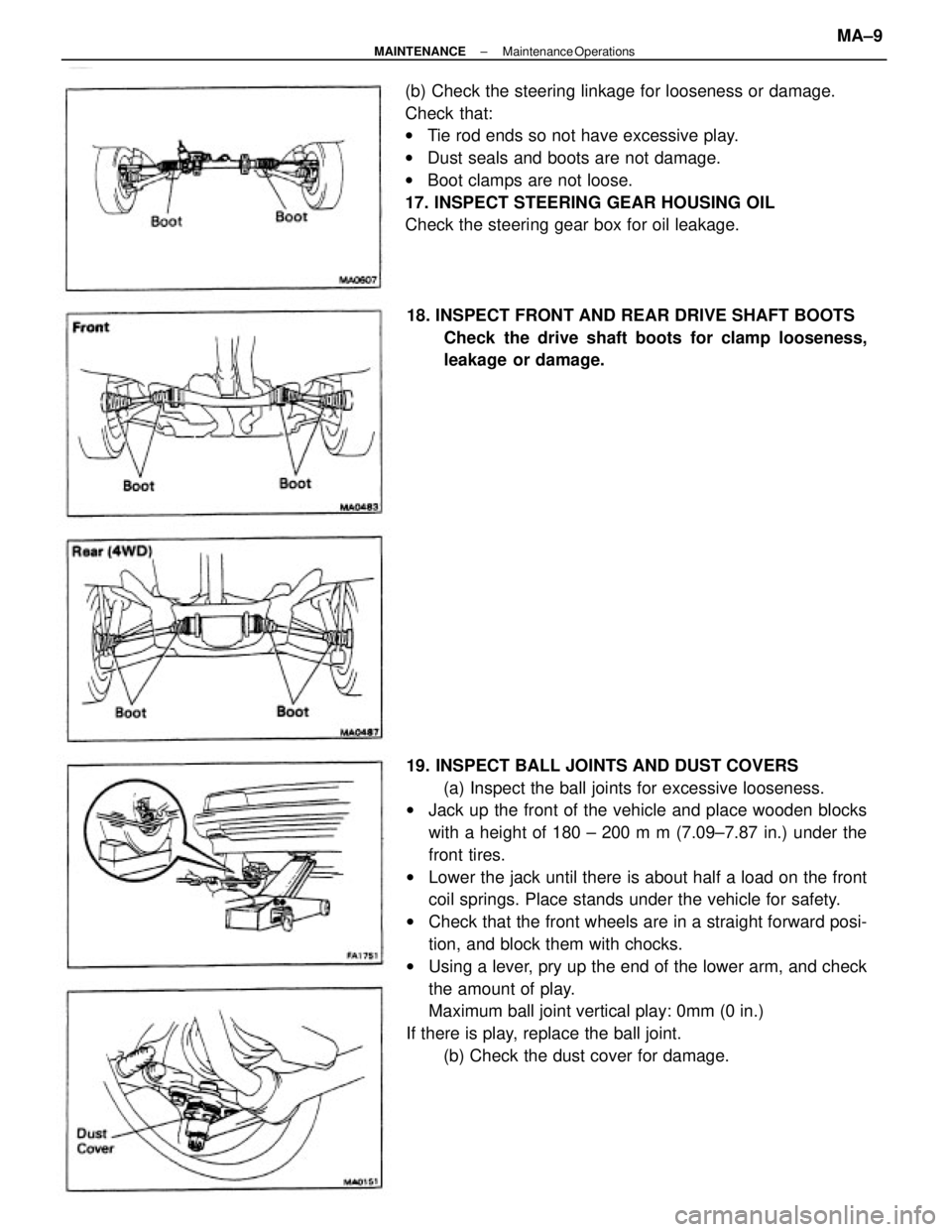
19. INSPECT BALL JOINTS AND DUST COVERS
(a) Inspect the ball joints for excessive looseness.
wJack up the front of the vehicle and place wooden blocks
with a height of 180 ± 200 m m (7.09±7.87 in.) under the
front tires.
wLower the jack until there is about half a load on the front
coil springs. Place stands under the vehicle for safety.
wCheck that the front wheels are in a straight forward posi-
tion, and block them with chocks.
wUsing a lever, pry up the end of the lower arm, and check
the amount of play.
Maximum ball joint vertical play: 0mm (0 in.)
If there is play, replace the ball joint.
(b) Check the dust cover for damage. (b) Check the steering linkage for looseness or damage.
Check that:
wTie rod ends so not have excessive play.
wDust seals and boots are not damage.
wBoot clamps are not loose.
17. INSPECT STEERING GEAR HOUSING OIL
Check the steering gear box for oil leakage.
18. INSPECT FRONT AND REAR DRIVE SHAFT BOOTS
Check the drive shaft boots for clamp looseness,
leakage or damage.
± MAINTENANCEMaintenance OperationsMA±9
Page 1927 of 2389
23. FINAL INSPECTION
(a) Check the operation of the body parts:
wHood
Auxiliary catch operation properly
Hood locks securely when closed
wFront and rear doors
Door locks operate properly
Doors close properly
wLuggage compartment door and back door
Door sock operates properly
wSeats
Seat adjusts easily and locks securely in any position
Front seat back locks securely in any position
Folding±down rear seat backs lock securely
(b) Road test
wCheck the engine and chassis for abnormal noises.
wCheck that the vehicle does not wander or pull to one side.
wCheck that the brakes work properly and do not drag.
wPerform bedding down of the parking brake shoes and drum.
(See page MA±8)
(c) Be sure to deliver a clean car especially check:
wSteering wheel
wShift lever knob
wAll switch knobs
wDoor handles
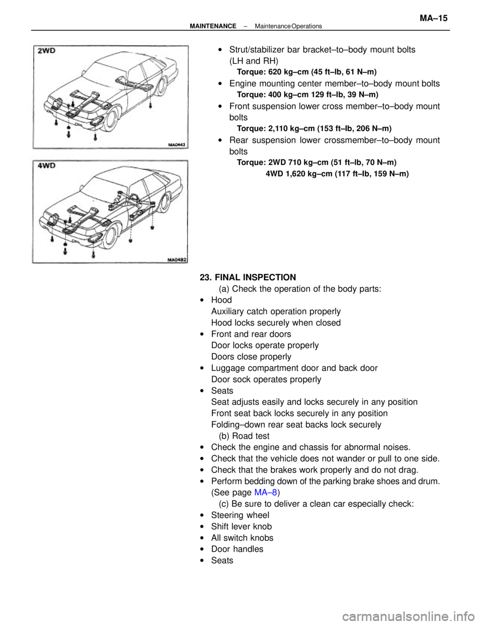
wSeatswStrut/stabilizer bar bracket±to±body mount bolts
(LH and RH)
Torque: 620 kg±cm (45 ft±lb, 61 N±m)
wEngine mounting center member±to±body mount bolts
Torque: 400 kg±cm 129 ft±lb, 39 N±m)
wFront suspension lower cross member±to±body mount
bolts
Torque: 2,110 kg±cm (153 ft±Ib, 206 N±m)
wRear suspension lower crossmember±to±body mount
bolts
Torque: 2WD 710 kg±cm (51 ft±lb, 70 N±m)
4WD 1,620 kg±cm (117 ft±Ib, 159 N±m)
± MAINTENANCEMaintenance OperationsMA±15
Page 2213 of 2389
Front and rear brake
Pad thickness
Disc thickness
Disc runout
Parking brake
Lining thickness
Drum inside diameter
Front axle and suspension
Ball joint vertical play
Steering wheel freeplay
Torque specifications
Front seat mount bolts
Strut/stabilizer bar bracket x Body
Engine mounting center member x Body
Front suspension lower crossmember x Body
Rear suspension lower crossmember x Body
MAINTENANCE
Engine
Engine oil capacity (Drain and refill with oil fitter change)
Gap
Firing order
Valve clearance Coolant capacity 1w/ Heater) Drive belt tension
Alternator
Spark plug
Type
Chassis
PS pump
± SERVICE SPECIFICATIONSMaintenanceA±2
Page 2269 of 2389
Wheel lateral runout
Tie rod end left±right error
Hub bearing axial direction play
Ball joint vertial play
Ball joint rotation condition
Drive shaft standard length
(FWD/SV21 /TOYOTA type/LH)
(FWD/SV21 /TOYOTA type/RH)
(FWD/SV21 /GKN type/LH)
(FWD/SV21 /GKN type/RH)
( FVIJD/VZV21)
(4WD/M/T/LH)
(4WD/A/T/LH)
(4WD/M/T/RH)
FRONT AXLE AND SUSPENSION
Specifications
Wheel angle
(FWD/SV21 and 4WD)
(FWD/VZV21)(FWD/SV21 and 4WD)
( FWD/VZV21)
Less than 3.0 mm/m (0.118 in./3.3 ft) (FWD/SV21 )
(4WD)
(F1ND/VZV21 )
Front axle
and suspensionChassis groung
clearance
Steering axis inclination Cold tire
inflation
pressure
Front wheel
alignment
Outside wheel (Max.)
Inside wheel (Max.)Adjustment STD
Inspection STD
Side slipCamber
Caster Toe±in
± SERVICE SPECIFICATIONSFront Axle and SuspensionA±31
Page 2275 of 2389
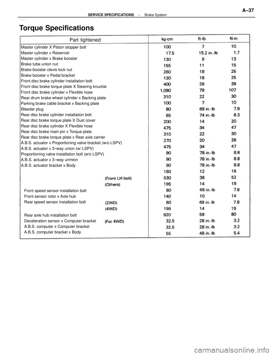
Master cylinder X Piston stopper bolt
Master cylinder x Reservoir
Master cylinder x Brake booster
Brake tube union nut
Brake booster clevis lock nut
Brake booster x Pedal bracket
Front disc brake cylinder installation bolt
Front disc brake torque plate X Steering knuckle
Front disc brake cylinder x Flexible hose
Rear drum brake wheel cylinder x Backing plate
Parking brake cable bracket x Backing plate
Bleeder plug
Rear disc brake cylinder installation bolt
Rear disc brake torque plate X Dust cover
Rear disc brake cylinder X Flexible hose
Rear disc brake main pin x Torque plate
Rear disc brake torque plate x Rear axle carrier
A.B.S. actuator x Proportioning valve bracket (w/o LSPV)
A.B.S. actuator x 3±way union (w/ LSPV)
Proportioning valve installation bolt (w/o LSPV)
A.B.S. actuator x 3±way unmion
A.B.S. actuator bracket x Body
Rear axle hub installation bolt
Deceleration sensor x Computer bracket
A.B.S. computer x Computer bracket
A.B.S. computer bracket x Body Front speed sensor installation bolt
Front sensor rotor x Axle hub
Rear speed sensor installation bolt
Torque Specifications
Part tightened
± SERVICE SPECIFICATIONSBrake SystemA±37